Transcription
EtherNet/IPModules inLogix5000 ControlSystems1756-ENBT, 1788-ENBT, 1769-L32E,1768-ENBT, 1794-AENT,1734-AENTUser Manual
Important User InformationSolid state equipment has operational characteristics differing from those ofelectromechanical equipment. Publication SGI-1.1, Safety Guidelines for theApplication, Installation and Maintenance of Solid State Controls (availablefrom your local Rockwell Automation sales office or online m) describes someimportant differences between solid state equipment and hard-wiredelectromechanical devices. Because of this difference, and also because ofthe wide variety of uses for solid state equipment, all persons responsible forapplying this equipment must satisfy themselves that each intendedapplication of this equipment is acceptable.In no event will Rockwell Automation, Inc. be responsible or liable forindirect or consequential damages resulting from the use or application ofthis equipment.The examples and diagrams in this manual are included solely for illustrativepurposes. Because of the many variables and requirements associated withany particular installation, Rockwell Automation, Inc. cannot assumeresponsibility or liability for actual use based on the examples and diagrams.No patent liability is assumed by Rockwell Automation, Inc. with respect touse of information, circuits, equipment, or software described in this manual.Reproduction of the contents of this manual, in whole or in part, withoutwritten permission of Rockwell Automation, Inc. is prohibited.Throughout this manual we use notes to make you aware of tifies information about practices or circumstancesthat can cause an explosion in a hazardous environment,which may lead to personal injury or death, propertydamage, or economic loss.Identifies information that is critical for successfulapplication and understanding of the product.Identifies information about practices or circumstancesthat can lead to personal injury or death, propertydamage, or economic loss. Attentions help you: identify a hazard avoid a hazard recognize the consequenceSHOCK HAZARDLabels may be located on or inside the drive to alertpeople that dangerous voltage may be present.BURN HAZARDLabels may be located on or inside the drive to alertpeople that surfaces may be dangerous temperatures.
Summary of ChangesThis document describes how to use EtherNet/IP modules inLogix5000 control systems. Revision bars in the margin identifyupdated information. This version of the document adds the1768-ENBT CompactLogix EtherNet/IP Communication Module.1For This InformationSee Page1768-ENBT Overview1-3Module LED IndicatorsA-1EtherNet/IP Network ConnectionsB-1Publication ENET-UM001E-EN-P - January 2006
Summary of Changes2Notes:Publication ENET-UM001E-EN-P - January 2006
Table of ContentsChapter 1About the Logix5000Communication Modules forEtherNet/IP NetworksUse This Chapter . . . . . . . . . . . . . . . . . . . . .1756-ENBT Overview . . . . . . . . . . . . . . . . . .1769-L32E, 1769-L35E Overview . . . . . . . . . .1768-ENBT Overview . . . . . . . . . . . . . . . . . .1788-ENBT Overview . . . . . . . . . . . . . . . . . .1794-AENT Overview . . . . . . . . . . . . . . . . . .1734-AENT Overview . . . . . . . . . . . . . . . . . .Use the EtherNet/IP Communication Modulesin a Control System . . . . . . . . . . . . . . . . . . . .Bridge Across Networks . . . . . . . . . . . . . . . .1-11-21-31-31-31-41-4. . . . . . . . . . 1-5. . . . . . . . . . 1-6Chapter 2Configure a Personal Computer to Use This Chapter . . . . . . . . . . . . . . . . . . . . . . . . . . . . . . . 2-1Configure the Ethernet Communication DriverOperate on an EtherNet/IPin RSLinx Software . . . . . . . . . . . . . . . . . . . . . . . . . . . . . . 2-2NetworkChapter 3Configure an EtherNet/IP Moduleto Operate on the NetworkUse This Chapter . . . . . . . . . . . . . . . . . . . . . . . . . . . . . .Determine Required Network Parameters. . . . . . . . . . . . .Assign Network Parameters via the BOOTP/DHCP Utility .Use Other Methods to Assign Network Parameters . . . . . .Duplicate IP Address Detection . . . . . . . . . . . . . . . . . . . .IP Address Swapping . . . . . . . . . . . . . . . . . . . . . . . . . . .DNS Addressing . . . . . . . . . . . . . . . . . . . . . . . . . . . . . . .Use the EtherNet/IP Modules in a Logix5000Controller Application . . . . . . . . . . . . . . . . . . . . . . . . . . .3-13-13-33-53-83-93-10. 3-11Chapter 4Control I/OiUse This Chapter . . . . . . . . . . . . . . . .Set Up the Hardware. . . . . . . . . . . . . .Set the Requested Packet Interval (RPI)Select a Communication Format. . . . . .Add Distributed I/O . . . . . . . . . . . . . .Access Distributed I/O . . . . . . . . . . . .4-14-14-24-24-94-11Publication ENET-UM001E-EN-P - January 2006
Table of ContentsiiChapter 5Interlocking and Data TransferBetween ControllersUse This Chapter . . . . . . . . . . . . . . . . . . . . . . . . . . . . . . .Set Up the Hardware . . . . . . . . . . . . . . . . . . . . . . . . . . . .Organize Tags for Produced or Consumed Data . . . . . . . .Determine Connections for Produced and Consumed TagsProduce a Tag . . . . . . . . . . . . . . . . . . . . . . . . . . . . . . . . .Consume Data Produced by Another Controller . . . . . . . .Guidelines for MSG Instructions . . . . . . . . . . . . . . . . . . . .Determine Connections for Messages . . . . . . . . . . . . . . . .Enter Message Logic. . . . . . . . . . . . . . . . . . . . . . . . . . . . .Configure a MSG Instruction. . . . . . . . . . . . . . . . . . . . . . .Communicate with PLC-5 or SLC Processors . . . . . . . . . . .5-15-15-35-45-55-65-95-105-105-135-17Chapter 6Send EmailUse This Chapter . . . . . . . . . . . . . . . . .Overview . . . . . . . . . . . . . . . . . . . . . .Send an Email Via a Controller-initiatedMessage Instruction . . . . . . . . . . . . . . .Enter the Text of the Email. . . . . . . . . .Possible Email Status Codes . . . . . . . . . . . . . . . . . . . . . . . 6-1. . . . . . . . . . . . . . . 6-1. . . . . . . . . . . . . . . 6-2. . . . . . . . . . . . . . 6-10. . . . . . . . . . . . . . 6-10Chapter 7Communicate With PanelViewTerminalsUse This Chapter . . . . . . . . . . . . . . . . . . . . . . . . . .Set Up the Hardware . . . . . . . . . . . . . . . . . . . . . . .Determine Connections to PanelView Terminals . . .Add a PanelView Terminal . . . . . . . . . . . . . . . . . . .Organize Controller Data for a PanelView Terminal.Determine Connections to RSView Applications . . .7-17-17-27-37-57-6.8-18-18-28-58-78-88-9Chapter 8Monitor DiagnosticsUse This Chapter . . . . . . . . . .Module Diagnostics . . . . . . . .Diagnostics Overview . . . . . .Network Settings . . . . . . . . . .Explicit Message Connections .I/O Connections . . . . . . . . . .Ethernet Statistics . . . . . . . . . .Appendix AModule LED IndicatorsPublication ENET-UM001E-EN-P - January 2006Use This Appendix . . . . . . . . . . . . . . . . . . . . . . . . . .1756-ENBT EtherNet/IP Communication Module . . . . .1769-L32E, 1769-L35E CompactLogix Controller. . . . . .1768-ENBT CompactLogix EtherNet/IPCommunication Module . . . . . . . . . . . . . . . . . . . . . . .1788-ENBT EtherNet/IP Communication Daughtercard1794-AENT EtherNet/IP FLEX I/O Adapter . . . . . . . . . . . . A-1. . . . A-2. . . . A-3. . . . A-4. . . . A-5. . . . A-7
Table of ContentsiiiAppendix BEtherNet/IP Network Connections Use This Appendix . . . . . . . . . . . . . . . . . . . . . . . . . . . . . . B-1CIP Connections . . . . . . . . . . . . . . . . . . . .TCP Connections . . . . . . . . . . . . . . . . . . . .Multicast Address Limit. . . . . . . . . . . . . . . .Specify the Requested Packet Interval (RPI).B-1B-4B-4B-5Use This Appendix . . . . . . . . . . . . . . . . . . .Ethernet Protocols . . . . . . . . . . . . . . . . . . . .Configuration Requirements . . . . . . . . . . . . .Manual Configuration on an Ethernet Switch.Change Ports on an Ethernet Switch . . . . . . .For More Information. . . . . . . . . . . . . . . . . .C-1C-1C-4C-7C-7C-8Appendix CEtherNet/IP Network OverviewIndexPublication ENET-UM001E-EN-P - January 2006
Table of ContentsivNotes:Publication ENET-UM001E-EN-P - January 2006
Chapter1About the Logix5000 Communication Modulesfor EtherNet/IP NetworksUse This ChapterEtherNet/IP ModuleThe Logix5000 family offers several EtherNet/IP communicationmodules. Select the module you need based on the EtherNet/IPfunctions you need.Works With a Controller to OriginateCommunication (Scanner/bridge)1756-ENBTX1756-EWEB(1)X1769-L32E, 1769-L35EX1768-ENBTX1788-ENBTXInterfaces With Distributed I/O Modules(Adapter)X1794-AENTX1734-AENTX(1)For more information about the 1756-EWEB module, see the EtherNet/IP Web Server Module User Manual, publication ENET-UM527.The EtherNet/IP communication modules: Support messaging, produced/consumed tags, anddistributed I/O. Encapsulate messages within standard TCP/UDP/IP protocol. Share a common application layer with ControlNet andDeviceNet protocols. Interface via RJ45, category 5, unshielded, twisted-pair cable. Support half/full duplex 10 Mbps or 100 Mbps operation. Require no network scheduling. Require no routing tables.1Publication ENET-UM001E-EN-P - January 2006
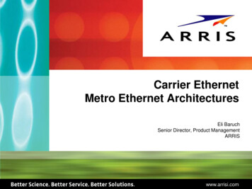
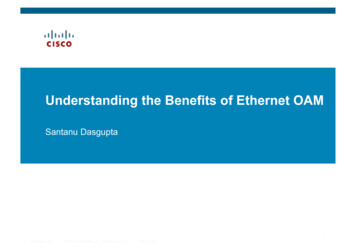
1-2About the Logix5000 Communication Modules for EtherNet/IP NetworksThis chapter introduces the modules listed above and describes howyou can use these modules in a control system:For This InformationSee Page1756-ENBT Overview1-21769-L32E, 1769-L35E Overview1-31768-ENBT Overview1-31788-ENBT Overview1-31794-AENT Overview1-41734-AENT Overview1-4Use the EtherNet/IP Communication Modules in a Control System1-5Bridge Across Networks1-6The remaining chapters in this publication describe how to configureand program the EtherNet/IP communication modules. A listing ofcatalog numbers at the beginning of each chapter identifies themodules that support the feature described in that chapter.1756-ENBT OverviewLINK NET OKPublication ENET-UM001E-EN-P - January 2006The 1756-ENBT module operates either as an interface for aControlLogix controller to communicate with other devices over anEtherNet/IP network or as an adapter for 1756 I/O modules on anEtherNet/IP network. This module supports: Control of I/O Communication via produced/consumed tags and MSGinstructions Communication with HMI Configuration and programming, such as upload, download Adapter functionality for 1756 I/O modules A web server to provide diagnostic and status information
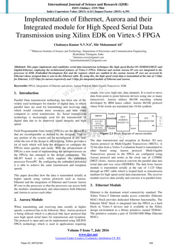
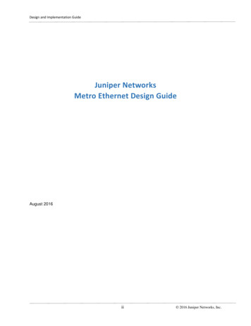
About the Logix5000 Communication Modules for EtherNet/IP Networks1769-L32E, 1769-L35EOverview1-3The 1769-L32E and 1768-L35E CompactLogix controllers have anintegrated EtherNet/IP port. Through this port, the controller supports: Control of I/O Communication via produced/consumed tags and MSGinstructions Communication with HMI Configuration and programming, such as upload, download A web server to provide diagnostic and status informationFor more information, see the CompactLogix System Manual,publication 1769-UM011.1768-ENBT OverviewThe 1768-ENBT module is an interface that lets a CompactLogixcontroller (1768-L43 or 1768-L45) communicate with devices over anEtherNet/IP network. The module supports: Control of I/O Communication via produced/consumed tags and MSGinstructions Communication with HMI Configuration and programming, such as upload, download A web server to provide diagnostic and status information1788-ENBT OverviewMSNSENETLNK U%The 1788-ENBT module operates as an interface for a FlexLogix andDriveLogix controller to communicate with other devices over anEtherNet/IP network. This module supports: Control of I/O Communication via produced/consumed tags and MSGinstructions Communication with HMI Configuration and programming, such as upload, download A web server to provide diagnostic and status informationPublication ENET-UM001E-EN-P - January 2006
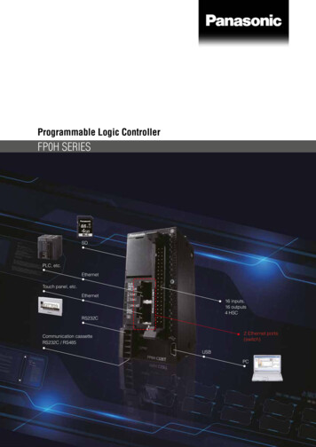
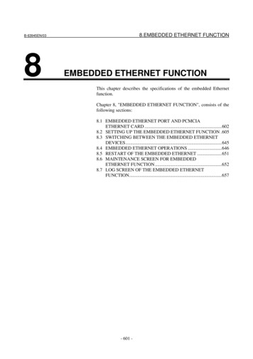
1-4About the Logix5000 Communication Modules for EtherNet/IP Networks1794-AENT OverviewThe 1794-AENT module operates as an adapter for FLEX I/O moduleson an EtherNet/IP network. This module supports: Control of I/O Configuration A web server to provide diagnostic and status information1734-AENT OverviewThe 1734-AENT module operates as an adapter for POINT I/Omodules on an EtherNet/IP network. This module supports: Control of I/O Configuration A web server to provide diagnostic and status informationModuleStatus0 0 NTSystemPowerFieldPowerThis module’s configuration process varies quite a bit from the othermodules described in this publication. For more information, see the1734-AENT User Manual, publication 1734-UM011.Publication ENET-UM001E-EN-P - January 2006
About the Logix5000 Communication Modules for EtherNet/IP NetworksUse the EtherNet/IPCommunication Modules ina Control System1-5This diagram shows how EtherNet/IP modules can fit into a controlsystem.FlexLogix Controller With1788-ENBT ModuleDistributed I/OControlLogixcontroller with1756-ENBTmodule1756-ENBT Module(As an Adapter) With1756 I/O ModulesCompactLogix1768-series ControllerWith EtherNet/IPCommunication ModuleCompactLogix1769-series ControllerWith IntegratedEtherNet/IP Portswitch1794-AENT Adapter With1794 I/O Modules1734-AENTAdapter With 1734I/O ModulesWorkstationIn this example: The controllers can produce and consume tags with each other. The controllers can initiate MSG instructions that send/receivedata or configure devices. The personal computer can upload/download projects to thecontrollers. The personal computer can configure devices on theEtherNet/IP network.Publication ENET-UM001E-EN-P - January 2006
1-6About the Logix5000 Communication Modules for EtherNet/IP NetworksBridge Across NetworksSome EtherNet/IP modules support the ability to bridge or routecommunication through devices, depending on the capabilities of theplatform and communication devices.The update time of local I/O modules may increase when bridgingmessages.IMPORTANTYou have a bridge when you have a connection betweencommunication devices on two separate networks. For example, thebridge device shown below has both EtherNet/IP and DeviceNetconnections so that Device 1 on the EtherNet/IP network cancommunicate with Device 2 on DeviceNet through the bridge.Device 1EtherNet/IP networkSwitchBridgeDeviceNet NetworkDevice 2CIP messages can bridge these networks:.CIP Messages That Originateon This NetworkCan Bridge to This NetworkEtherNet/IPControlNetDeviceNetRS-232 sRS-232yesyesyesyesPublication ENET-UM001E-EN-P - January 2006
About the Logix5000 Communication Modules for EtherNet/IP Networks1-7In this example, a workstation configures a drive on a DeviceNetnetwork. The workstation bridges EtherNet/IP networks to reach thedrive.PanelView StationWorkstationEtherNet/IP NetworkSwitchBridgeDeviceNet NetworkPWRSTSPORTMODNET ANET BDriveIn this example, the bridge can be an EtherNet/IP to DeviceNetbridging device or a Logix5000 system with an EtherNet/IPcommunication module and a DeviceNet communication module. Thebridge can be a: ControlLogix chassis with a 1756-ENBT module and a 1756-DNBmodule. The controller is not required. 1769-L32E, 1769-L35E, and 1768-L43 CompactLogix controllerwith a 1769-SDN module. FlexLogix controller with 1788-ENBT and 1788-DNBO modules. 1788-EN2DN linking device.In the example above, status data can also be transferred fromDeviceNet through the Logix5000 controller to a RSView32 operatorinterface. For a CompactLogix or FlexLogix controller, map the datainto the DeviceNet I/O image and then use RSLinx OPC from the PCto the Logix5000 controller over the EtherNet/IP network. This avoidsusing the limited bridging resources of the CompactLogix or FlexLogixcontroller.You cannot bridge EtherNet/IP I/O across networks. I/O modulesmust be configured in either a local chassis or a remote chassis. Youcannot go through a gateway chassis to control I/O, even though insome circumstances, RSLogix 5000 software accepts such aconfiguration in the I/O Configuration folder.Publication ENET-UM001E-EN-P - January 2006
1-8About the Logix5000 Communication Modules for EtherNet/IP NetworksThis example RSLinx software screen shows how the DeviceNetbridge links to the EtherNet/IP network.EtherNet/IP NetworkEtherNet/IP Bridge in1756 SystemDeviceNet Bridge inSame 1756 SystemDeviceNet NetworkDistributed DeviceNetDevicesPublication ENET-UM001E-EN-P - January 2006
Chapter2Configure a Personal Computer to Operate onan EtherNet/IP NetworkUse This ChapterRead thischapter for: 1756-ENBT module 1769-L32E, -L35E controller 1768-ENBT module 1788-ENBT card 1794-AENT adapterThis chapter describes how to configure a personal computer tooperate on an EtherNet/IP network.For This InformationSee PageConfigure the Ethernet Communication Driver in RSLinxSoftware2-2You need to load an Ethernet communication driver for all RockwellSoftware applications to communicate with devices on an EtherNet/IPnetwork. A personal computer needs this driver if you use thepersonal computer to perform such tasks as: Upload and download controller projects over the EtherNet/IPnetwork via RSLogix 5000 programming software Configure EtherNet/IP network parameters for devices on thenetwork via RSNetWorx for EtherNet/IP software Collect controller data for PanelView terminals and RSViewapplicationsBefore you load a communication driver, make sure the Ethernet communication card is already installed in the personalcomputer. IP address and other network parameters are correctlyconfigured for the personal computer. Personal computer is properly connected to the EtherNet/IPnetwork.See the documentation for the appropriate Ethernet communicationcard for information on installing and configuring the card.1Publication ENET-UM001E-EN-P - January 2006
2-2Configure a Personal Computer to Operate on an EtherNet/IP NetworkConfigure the EthernetCommunication Driver inRSLinx SoftwareTo configure the Ethernet communication driver for the personalcomputer (programming workstation):1. In RSLinx software, select Configure Drivers. Select EtherNet/IPDriver or Ethernet devices.This example shows the EtherNet/IP Driver selection because itlets you autobrowse to select the appropriate device. If youselect the Ethernet Devices selection, you have to enter theIP address of the device. See RSLinx online help for moreinformation.2. Click Add New to add the driver.Enter a name for the driver.Publication ENET-UM001E-EN-P - January 2006
Configure a Personal Computer to Operate on an EtherNet/IP Network2-33. Select Browse Local Subnet. This displays the devices on thelocal network so you can navigate to the EtherNet/IPcommunication module for the controller you want to program.After you navigate to the appropriate EtherNet/IPcommunication module, click OK.4. The driver is now available and you can select the Ethernet portfrom Who Active in RSLogix 5000 programming software.Publication ENET-UM001E-EN-P - January 2006
2-4Configure a Personal Computer to Operate on an EtherNet/IP NetworkNotes:Publication ENET-UM001E-EN-P - January 2006
Chapter3Configure an EtherNet/IP Module to Operateon the NetworkUse This ChapterRead thischapter for: 1756-ENBT module 1769-L32E, -L35E controller 1768-ENBT module 1788-ENBT card 1794-AENT adapterThis chapter describes how to configure an EtherNet/IPcommunication module to operate on an EtherNet/IP network.For This InformationSee PageDetermine Required Network Parameters3-1Assign Network Parameters via the BOOTP/DHCP Utility3-3Use Other Methods to Assign Network Parameters3-5Duplicate IP Address Detection3-8IP Address Swapping3-9DNS Addressing3-10Use the EtherNet/IP Modules in a Logix5000 ControllerApplication3-11When you first install a Rockwell Automation EtherNet/IP module(right out of the box), the module is BOOTP/DHCP enabled.Determine RequiredNetwork ParametersTo operate on an EtherNet/IP network, you must define theseparameters:EtherNet/IP Network ParameterDescriptionIP addressThe IP address uniquely identifies the module. The IP address is in the formxxx.xxx.xxx.xxx where each xxx is a number between 0-255. These are reserved valuesyou cannot use: 127.0.0.1 0.0.0.0 255.255.255.255Subnet maskSubnet addressing is an extension of the IP address scheme that allows a site to use asingle network ID for multiple physical networks. Routing outside of the site continues bydividing the IP address into a net ID and a host ID via the class. Inside a site, the subnetmask is used to redivide the IP address into a custom network ID portion and host IDportion. This field is set to 0.0.0.0 by default.If you change the subnet mask of an already-configured module, you must cycle power tothe module for the change to take effect.Gateway1A gateway connects individual physical networks into a system of networks. When a nodeneeds to communicate with a node on another network, a gateway transfers the databetween the two networks. This field is set to 0.0.0.0 by default.Publication ENET-UM001E-EN-P - January 2006
3-2Configure an EtherNet/IP Module to Operate on the NetworkIf you use DNS addressing, or reference the module via host name inMSG instructions, define these parameters:EtherNet/IP Network ParameterDescriptionHost nameA host name is part of a text address that identifies the host for a module. The full textaddress of a module is host name.domain name.Domain nameA domain name is part of a text address that identifies the domain in which the moduleresides. The full text address of a module is host name.domain name. The domain namehas a 48-character limit.If you specify a DNS server, you must enter a domain name. Also, if you send email fromthe module, some mail relay servers require a domain name be provided during the initialhandshake of the SMTP session.Primary DNS server addressSecondary DNS server addressThis identifies the DNS server(s), if used in the network. You must have a DNS serverconfigured if you specified a domain name or a host name in the module’s configuration.The DNS server converts the domain name or host name to an IP address that can be usedby the network.The 1756-ENBT requires a DNS server address.For more information on DNS addressing, see page 3-10.Check with your Ethernet network administrator to determine if youneed to specify all of the above parameters.To configure these network parameters, the recommended method isto use the Rockwell Automation BOOTP/DHCP utility (see page 3-3).If this utility is not available, there are other methods you can use (seepage 3-5).Publication ENET-UM001E-EN-P - January 2006
Configure an EtherNet/IP Module to Operate on the NetworkAssign NetworkParameters via theBOOTP/DHCP UtilityIMPORTANT3-3By default, the EtherNet/IP module is BOOTP enabled. TheBOOTP/DHCP utility is a standalone program that is located in the: BOOTP-DHCP Server folder in the Rockwell Software programfolder on the Start menu (the utility is automatically installedwhen you install RSLinx software). Tools directory on the RSLogix 5000 installation CD.Before you start the BOOTP/DHCP utility, make sure you have thehardware (MAC) address of the module. The hardware address ison a sticker located on the side of the EtherNet/IP module. Thehardware address in a format similar to: 00-0b-db-14-55-35.This utility recognizes BOOTP-enabled devices and provides aninterface to configure a static IP address for each device.To use the BOOTP/DHCP utility:1. Start the BOOTP/DHCP software.2. Select Tool Network Settings.If appropriate for your network, enter the subnet mask, gatewayaddress, primary/secondary server addresses, and domain name.Click OK.Publication ENET-UM001E-EN-P - January 2006
3-4Configure an EtherNet/IP Module to Operate on the Network3. In the Request History panel you see the hardware addresses ofmodules issuing BOOTP requests. Double-click on the hardware(MAC) address of the module you want to configure.The hardware address is on a sticker located on the side of theEtherNet/IP module. The hardware address will be in a formatsimilar to 00-0b-db-14-55-35.4. The New Entry window appears with the module’s EthernetAddress (MAC).Enter the IP address or the host name. You can also enter adescription of the module. Click OK5. To permanently assign this configuration to the module,highlight the module and click on the Disable BOOTP/DHCPbutton. When power is recycled, the module uses theconfiguration you assigned and not issue a BOOTP request.If you do not select the Disable BOOTP/DHCP button, on apower cycle, the host controller clears the current IPconfiguration and will again begin sending BOOTP requests.Publication ENET-UM001E-EN-P - January 2006
Configure an EtherNet/IP Module to Operate on the NetworkUse Other Methods toAssign NetworkParameters3-5Other methods to assign network parameters include:IfUse This Method For Assigning Network Parameter See Page A BOOTP server is not availableRSLinx software3-5 The RSLogix 5000 project is online with thecontroller that communicates to or through theEtherNet/IP moduleRSLogix 5000 software3-7 DHCP is enabled (not BOOTP) for the EtherNet/IPmoduleDHCP software3-7 the EtherNet/IP module is connected to anotherNetLinx networkOther considerations that might affect your choice of method include: Whether the network is isolated from or integrated into theplant/enterprise network Size of the networkFor large networks, even isolated networks, it might be moreconvenient and safer to use a BOOTP/DHCP server rather thanRSLogix 5000 or RSLinx software. It might also offer feweropportunities for assigning duplicate IP addresses. Company policies and procedures dealing with plant floornetwork installation and maintenance Level of involvement by IT personnel in plant floor networkinstallation and maintenance Type of training offered to control engineers and maintenancepersonnelIf you use the Rockwell Automation BOOTP or DHCP server in anuplinked subnet where an enterprise DHCP server exists, a modulemay get an address from the enterprise server before the RockwellAutomation utility even sees the module. You might have todisconnect from the uplink to set the address and have the moduleremember its static address before reconnecting to the uplink. This isnot a problem if you have node names configured in the module andleave DHCP enabled.Using RSLinx software to set the IP addressTo use RSLinx to configure the EtherNet/IP module:1. Make sure the module is installed and powered up.Publication ENET-UM001E-EN-P - January 2006
3-6Configure an EtherNet/IP Module to Operate on the Network2. Start RSLinx. The RSWho window opens. Navigate in RSWho tothe Ethernet network.3. Right-click on the EtherNet/IP module (not the controller, ifthere is one) and select Module Configuration.4. Select the Port Configuration tab, choose Status NetworkConfiguration type, and enter the IP address and the othernetwork parameters, if needed.Also, select the Static radio button to permanently assign thisconfiguration to the port. If you select Dynamic, on a powercycle, the controller clears the current IP configuration and willagain begin sending BOOTP requests.Publication ENET-UM001E-EN-P - January 2006
Configure an EtherNet/IP Module to Operate on the Network3-7Use RSLogix 5000 software to set the IP addressTo use RSLogix 5000 software to configure the EtherNet/IP module:1. Make sure the module is installed and has power.2. Connect to the controller via a serial, or other network,connection.3. Start RSLogix 5000 software. In the Controller Organizer, selectproperties for the EtherNet/IP module.4. Select the Port Configuration tab and specify the IP address andthe other network parameters, if needed. Click Apply and thenclick OK.This sets the IP address in the hardware. This IP address shouldbe the same IP address you assigned under the General tab.On this screen, you can also specify port speed (10 Mbps or100 Mbps) and duplex mode (autonegotiate, half duplex, or fullduplex). All modules on the same subnet must be configured forthe same port speed and duplex mode.Use DHCP software to set the IP addressDynamic Host Configuration Protocol (DHCP) software automaticallyassigns IP addresses to client stations logging onto a TCP/IP network.DHCP is based on BOOTP and maintains some backwardcompatibility. The main difference is that BOOTP allows for manualconfiguration (static), while DHCP allows for both static and dynamicPublication ENET-UM001E-EN-P - January 2006
3-8Configure an EtherNet/IP Module to Operate on the Networkallocation of network addresses and configurations to newly attachedmodules.Be cautious when using DHCP software to configure your module. ABOOTP client, such as the EtherNet/IP modules, can boot from aDHCP server only if the DHCP server is specifically written to alsohandle BOOTP queries. This is specific to the DHCP software packageyou use. Check with your system administrator to see if your DHCPpackage supports BOOTP commands and manual IP allocation.ATTENTION!Duplicate IP AddressDetectionThe EtherNet/IP module must be assigned a fixednetwork address. The IP address of this module mustnot be dynamically provided.Failure to observe this precaution may result inunintended machine motion or loss of processcontrol.These EtherNet/IP modules (and their future revis
EtherNet/IP Modules in Logix5000 Control Systems 1756-ENBT, 1788-ENBT, 1769-L32E, 1768-ENBT, 1794-AENT, 1734-AENT User Manual