Transcription
HardwareX 12 (2022) e00325Contents lists available at ScienceDirectHardwareXjournal homepage: www.elsevier.com/locate/ohxHardware ArticleUAV rapidly-deployable stage sensor with electro-permanentmagnet docking mechanism for flood monitoring inundersampled watershedsCorinne Smith a, , Joud Satme a, Jacob Martin a,b, Austin R.J. Downey a,c,Nikolaos Vitzilaios a, Jasim Imran cabcUniversity of South Carolina, Department of Mechanical Engineering, Columbia, SC, United StatesUniversity of South Carolina, Department of Physics and Astronomy, Columbia, SC, United StatesUniversity of South Carolina, Department of Civil Engineering, Columbia, SC, United Statesa r t i c l ei n f oArticle history:Keywords:stageflood monitoringrapidly-deployableUAVwater heightultrasonic sensora b s t r a c tThe availability of historical flood data is vital in recognizing weather-related trends andoutlining necessary precautions for at-risk communities. Flood frequency, magnitude,endurance, and volume are traditionally recorded using established streamgages; however,the material and installation costs allow only a few streamgages in a region, which yield anarrow data selection. In particular, stage, the vertical water height in a water body, is animportant parameter in determining flood trends. This work investigates a low-cost, compact, rapidly-deployable alternative to traditional stage sensors that will allow for densersampling within a watershed and a more detailed record of flood events. The package usesa HC-SR04 ultrasonic sensor to measure stage, onboard memory for recording flood events,and an electropermanet magnet (EPM) to enable Unmanned Aerial Vehicle (UAV) deployments. Optional modules for solar panels and wireless communication can also be added toextend package longevity or allow wireless control of the EPM. The stage sensor packagewas found to have a range of 0.02 to 4 m with a 6.9 mm accuracy and capable of a6.4 day long deployment. With the total cost of production at 271.37 USD, it is a cheaperand more flexible alternative to traditional stage sensors that will enable dense sensor networks and rapid response to flooding events.Ó 2022 The Author(s). Published by Elsevier Ltd. This is an open access article under the CCBY license ifications tableHardware nameSubject areaHardware typeStage sensor packageEnvironmental, planetary and agricultural sciencesField measurements and sensors(continued on next page)Abbreviations: UAV, Unmanned Aerial Vehicle; EPM, Electro-permanent magnet. Corresponding author.E-mail address: cas48@email.sc.edu (C. 68-0672/Ó 2022 The Author(s). Published by Elsevier Ltd.This is an open access article under the CC BY license (http://creativecommons.org/licenses/by/4.0/).
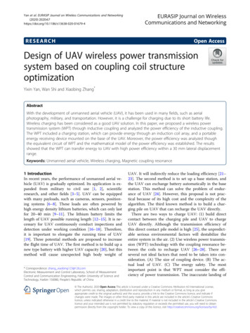
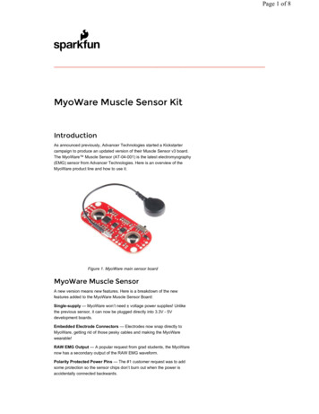
C. Smith, J. Satme, J. Martin et al.Closest commercial analogOpen source licenseCost of hardwareSource file repositoryHardwareX 12 (2022) e00325USGS rapid deployment gageCC-BY Attribution 4.0 International 271.37https://doi.org/10.17605/OSF.IO/A874U1. Hardware in ContextFlooding is on average the second deadliest weather-related hazard in the United States, causing 57 fatalities and inflicting over 1 billion in crop and property damage in 2020 alone [1]. Flash floods are characterized by intense, nucleated rainfallthat drains into a common basin, usually too small to accommodate the volume of runoff generated by the localized storm.The swiftness and severity of the rainfall results in very sudden flooding, even if the rainfall is further upstream from thebasin [2]. Built environments have become especially susceptible to flooding, as the increase in both rainfall events andimpervious surfaces in heavily populated areas increase the occurrence of urban flooding [3]. For example, the Rocky BranchWatershed is an urban watershed located in Columbia, South Carolina, and is 97% developed with a high percentage ofimpervious surfaces [4].Recent work at the regional level using a peaks-over-threshold approach to analyze flood magnitude and frequencytrends has found that the magnitude of flood peaks has remained relatively consistent, however the frequency of historicflood events has increased significantly [5]. Frequent minor flooding, called nuisance flooding, has been found to have socioeconomic impacts on communities comparable to those incurred by extreme flooding, particularly for coastal communities[6]. On a larger scale, data from 375 streamgages across the contiguous United States was analyzed and revealed fragmentedpatterns of flood change that vary widely between geographical regions, with no real evident trends over large portions ofthe US [7]. The results of this study also conclude that even intraregional watersheds can exhibit high variability in trendsconcerning flood frequency, magnitude, duration, and volume. Due to this fragmentation, denser sampling within watersheds may provide a clearer picture of flood behavior on the regional scale. An extensive record of flood frequency and magnitude is crucial in planning for extreme disasters, assessing possible damages inflicted by nuisance flooding, andunderstanding flood trends within an area.Stage is the vertical position of the water surface relative to an arbitrarily defined datum, and is a vital parameter in monitoring flood events. The United States Geological Survey (USGS) is a government agency that has established streamgages allthroughout the US that collect data concerning weather events such as rainfall, water quality, and stage [8]. A USGS stagesensor can come in a variety of forms, including stilling wells, bubble gages, ultrasonic, and radar sensors. Stilling wellsare typically 1.2 meters in diameter and operate by allowing stream water to enter through a pipe so that the water insidethe well is at the same level as the water surface of the water body [9]. The water level inside the well is then measured usinga float, pressure, ultrasonic, or optic sensor, and the data is logged electronically for a set time interval [10].Bubble gages are a cheaper alternative to stilling wells [11]. These gages determine stage using pressure differences. Along tube is submerged and pressurized gas is pumped from a gage house to an opening in the tube. The hydrostatic pressureof the water determines the pressure reading inside the tube, so an increase in the water level translates to an increase in thehydrostatic pressure of the water and tube. The tube pressure is then converted to a stage value [11]. The bubble gagerequires equipment housing, most often a look-in type of shelter that includes the pressure sensing equipment, a battery,an antenna for data transmission, and solar panels for battery charging. Both stilling wells and bubble gages are connectedto gage houses that are equipped to collect stage data along with other parameters such as temperature, pH, and dissolvedchemicals [11]. The downside of these stations is that they are large and permanent, prohibiting the transplant of a station toa more at-risk area. USGS stations are also expensive, limiting the number of gages established in a watershed and constraining the sampling density.Rapidly-deployable sensors, such as the USGS Rapid-Deployment Gages (RDGs), are deployed temporarily to measurehydraulic parameters in emergency situations. The USGS RDGs contain a radar-based stage sensor, radio transmission,and solar panels, and are manually installed by bolting brackets onto a bridge. These are considerably smaller and more portable than the permanent gages, but they are still large and require experts to install [12]. Installing one of these RDGs in anemergency situation poses safety issues for the person installing the station as they are heavy, somewhat difficult to install,and would have to be deployed manually in inclement weather. Diagrams of each USGS gage type can be seen in Fig. 1.The development of a Unmanned Aerial Vehicle (UAV)-deployable stage sensor package is reported in this work. As presented in Fig. 2, the UAV-deployable stage sensor package is designed to be mounted to the underside of ferrous structuresusing an electro-permanent magnet (EPM). The magnetic field of EPMs can be toggled on and off using electrical pulses[13,14]. EPMs do not require constant power to remain enabled like an electromagnet, and are therefore ideal for longterm deployments. The stage sensor can be configured with modular add-on packages consisting of a solar module and awireless control module for the remote activation/deactivation of the EPM.The base package is the simplest package meant for manual deployments lasting no longer than 6 days. The solar add-onmodule is suitable for longer deployments, as the use of solar load sharing prolongs the package’s lifespan depending on theamount of available solar radiation. The wireless control add-on module is most ideal for UAV applications as it allows UAV2
HardwareX 12 (2022) e00325C. Smith, J. Satme, J. Martin et al.Fig. 1. Types of USGS stage gages: a) stilling well, b) bubble gage with look-in housing, c) rapid-deployment gage.Fig. 2. Stage sensor package deployed under a ferrous structure with solar add-on module.deployment using wireless control of the EPM. The EPM can be enabled and disabled from up to 10 meters away from theuser, which is optimal for structures out of reach for manual deployment. A drawback of the magnet module is that the radiofrequency (RF) protocol consumes over twice the power of the base package, resulting in shorter deployments. It is important to note that the solar and wireless control add-on modules are built on top of the same base package hardware and canbe combined in one form factor to extend the life of the package. Each package is capable of measuring stage, humidity, temperature, and ambient atmospheric pressure.3
C. Smith, J. Satme, J. Martin et al.HardwareX 12 (2022) e00325This paper begins with an overview of the stage sensor package’s hardware and software, including the design characteristics, sensing technology, and data collection protocols. A list of design files and materials is presented, along with build andoperation instructions. The paper concludes with tests validating sensor accuracy, deployment longevity, and a field study.The base package is explored in depth throughout this work and is used in all validation tests. The solar and wireless controladd-on modules are specifically mentioned in their individual sections.2. Hardware Description2.1. OverviewThe stage sensor package was developed with the following design goals:1.2.3.4.5.6.7.Cost under 300 USD per unitLightweight design suitable for UAV deploymentMulti-day deploymentsWide range of operating conditions regarding temperature, humidity, etcWireless control for EPM during UAV deploymentProduce comparable results to the USGS bubble gagesBattery power monitoring systemFig. 3 shows the internal components of the sensor package. The most basic datalogger contains a microprocessor, timekeeping device, and data storage device. The stage sensor package utilizes the Arduino Nano development board with anATmega328P microcontroller. This particular microcontroller was chosen for its low power capabilities, many digital I/Opins, and SPI, I2C, and UART communication protocols. The 14 I/O pins allow for a large number of sensors to be includedin the package, while the communication protocols facilitate fast, accurate sensor readings. A micro SD card module is featured to allow onboard data storage via SPI communication. The package employs the DS3231 real-time clock for time keeping, which uses I2C protocol to provide time stamps for sensor readings, allow consistent time intervals between collectioncycles, and wake the microcontroller from its low power sleep mode. The DS3231 requires an external 3 V coin cell to provide power to the clock during sleep mode when the package is not being powered by the 7.4 V, 1500 mAh, lithium polymerbattery.To measure ambient environmental conditions, the BME280 environmental sensor was added. This sensor communicatestemperature, humidity, and pressure readings via I2C. As the package is deployed outdoors, this sensor is useful for detectingconditions that may be associated with an incoming severe weather event. To avoid an overdischarged battery while thepackage is deployed, the INA219 current sensor was added to monitor the battery voltage, current, and power consumption.Table 1 gives an overview of the specifics of the sensor package.Fig. 3. Internal components of sensor package a) front and b) back. The internal hardware is housed in the c) external assembly during deployment.4
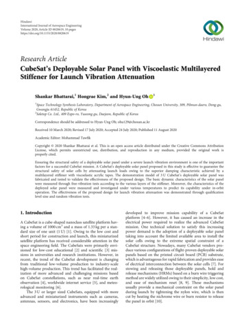
HardwareX 12 (2022) e00325C. Smith, J. Satme, J. Martin et al.Table 1Design characteristics of stage sensor package.Package typeParameterBase packageWeightBattery lifeActive current drawStandby current drawStage range0.38 kg6.4 days18 mA9 mA0.02–3.5 mBase package with solar add-on moduleWeightBattery life (ideal conditions)Max load sharing currentActive current drawStandby current drawStage range0.43 kg13 days159.2 mA18 mA9 mA0.02–3.5 mBase package with wireless control add-on moduleWeightBattery lifePeak current draw during toggleActive current drawStandby current drawStage rangeRF range0.38 kg2.8 days384 mA31 mA22 mA0.02–3.5 m10 mBase package with solar add-on module & wireless control add-on moduleWeightBattery life (ideal conditions)Max load sharing currentPeak current draw during toggleActive current drawStandby current drawStage rangeRF Range0.43 kg5 days159.2 mA384 mA31 mA22 mA0.02–3.5 m10 m2.2. Ultrasonic SensingThe HC-SR04 ultrasonic sensor is used to measure the water level. The sensor uses a 40 kHz burst of ultrasound to measure the distance from the HC-SR04 at the base of the package to the water surface [15]. The stand-off measurement capability of the HC-SR04 made it an ideal choice for a UAV deployable package as it eliminates the need for submerged parts,which are required in the typical USGS bubble gages and stilling wells. Additionally, an ultrasonic sensor was chosen insteadof a LiDAR sensor, another contactless method of measuring distance, due to LiDAR’s unsuitability for water applications[16]. The sensor has two transducers: the transmitter which converts the electrical signal from the microcontroller intoan ultrasonic pulse, and the receiver that converts the reflected ultrasonic pulse back into an electrical signal to send tothe microcontroller [17]. These two transducers are enclosed in metal cylinders on the sensor, which are exposed throughtwo holes at the base of the stage sensor package. Fig. 4 outlines the timing diagram and working principle of the HC-SR04.The transducers in the HC-SR04 ultrasonic sensor have an effectual angle of 30 degrees [15], which is important as it constrains the distance a sensor package can be placed from any lateral obstructions, such as a bridge girder. For example, if thesensor package is placed at its maximum height of 4 m from the water surface, there may be no obstructions from the surfacewithin a 1.07 m radius directly below the transducers of the HC-SR04. The transducers should be positioned parallel to thewater’s surface to ensure the ultrasound reflects directly back toward the sensor. Once the microcontroller signals the HCSR04 to take a distance reading, a 10 ls trigger output causes the transmitter to emit a 8 cycle 40 kHz ultrasonic burst. Thereceiver waits for the reflected 8 cycle 40 kHz signal, and when it picks up the same frequency, the echo pin of the sensor isdriven high for the corresponding length of the delay between transmitter output and receiver input [17]. This signal is sentto the microcontroller and converted into a distance reading. It is important that each data collection cycle must be at least50 ls long to avoid overlapping pulses. Fig. 5.2.3. PowerLongevity is an important feature for the stage sensor package. The package has been optimized for maximum battery life,as it is uncertain how long a package should be deployed during a severe weather event. The ATmega328P has a sleep modefeature which allows for the power consumption to be reduced by cutting off all peripheral pins, including communicationprotocols, except for the interrupt pins. These interrupt pins will disable sleep mode when triggered, waking the microcontroller up for 6 s to record and save data, then allow the Arduino Nano to immediately resume sleep mode. One interrupt pinis attached to the real-time clock and is triggered every five minutes to run a data collection cycle. The second interrupt pin iswired to the nRF24L01 to wake the microcontroller when a ping is sent from the RF controller to toggle the EPM in thewireless control module. It is important to note that although the ATmega328P is in sleep mode, there still exists steady statepower consumption from the modules on the PCB.5
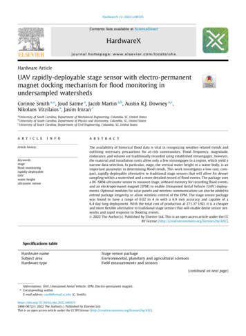
C. Smith, J. Satme, J. Martin et al.HardwareX 12 (2022) e00325Fig. 4. Timing diagram of HC-SR04 ultrasonic sensor.Fig. 5. Block diagram of the stage sensor package.2.4. SoftwareThe basic data logging process of the stage sensor package is displayed in Fig. 6. The software of the stage sensor packageis Arduino-language based. When first powered on, the ATmega328P configures all of the modules and then immediatelysleeps for five minutes. The data collection process begins with the DS3231 sending an interrupt to wake up the microcontroller to execute the data collection and logging code. The HC-SR04 first takes five stage readings that are communicated tothe microcontroller via PWM, and all non-zero distance measurements are averaged. The BME280 then measures tempera6
HardwareX 12 (2022) e00325C. Smith, J. Satme, J. Martin et al.Fig. 6. Algorithm for data collection and processing performed by the stage sensor package.ture, pressure, and humidity and sends the readings via I2C to the ATmega328P. Finally, the INA219 reads the voltage, current, and power draw from the battery and also relays the values via I2C. Once all the sensor readings are taken, they are thenwritten in a.csv file that is saved on the SD card using SPI, along with a time stamp of when the data was taken. After the datais written, another five-minute alarm is configured for the DS3231 before the ATmega328P is put back into sleep mode.When the alarm is triggered, the entire data collection process will repeat.2.5. Solar Add-on ModuleLoad sharing with solar panels is an effective strategy to extend the deployment period of the package. The idea behindload sharing is that the package will draw power from the solar panels first, then supplement additional power needs withthe 7.4 V LiPo battery. The solar cells are not recharging the battery, but rather acting as an alternative power source, meaning the 7.4 V LiPo battery should be recharged after deployment. Fig. 7 shows the block diagram of the solar add-on moduleand its outer frame. The 3D printed solar ring contains six chambers, each for one SM500K12L Anysolar 132.3 mW solarpanel. The panels are configured so that three panels are wired in series, then two sets of three are wired in parallel. Thisallows for a maximum voltage of 20.1 V and current draw of 39.6 mA. The solar ring has a connector that is inserted throughthe solar port on the EPM housing and plugs into the daughter board. The voltage from the solar panels is stepped down witha 5 V regulator on the daughter board, which in turn steps up the current draw to a maximum of 159.2 mA.In the field, the packages will likely be deployed under structures that block sunlight, so the power generated may bemuch less than the maximum, which is why solar panels that provide much more power than necessary for the packagewere chosen. Additionally, solar panels are light and compact, making them suitable for the UAV deployable design goalas opposed to alternative power sources.2.6. Wireless Control Add-on ModuleThe wireless control add-on module allows the EPM to be controlled remotely. Contrary to the base package, which treatsthe EPM as a permanent magnet and is manually deployed, the wireless control module allows the EPM to be toggled on andoff with an RF controller. This is useful for UAV deployment, as the user can attach and detach the package from a structureout of reach for manual deployment.The wireless control module requires an RF controller to toggle the EPM. The controller can be paired with up to threedifferent packages, making it suitable for deploying multiple packages in a network. The wireless control module uses RFcommunication via the nRF24L01 2.4 GHz wireless module located on both the controller and the package itself. ThenRF24L01 on the controller sends a ping to the nRF24L01 on the package, which then signals the ATmega328P to supply7
C. Smith, J. Satme, J. Martin et al.HardwareX 12 (2022) e00325Fig. 7. Solar module implemented on the base package. Solar load sharing is incorporated in the a) block diagram of the daughter board and b) externalframe of solar package.power to the EPM and send a PWM signal to the magnet that will either toggle it on or off, depending on the ping sent fromthe controller. As the EPM does not need power after it is enabled and attached to the structure, a magnet power controlcircuit on the daughter board consisting of a high-side switch disconnects the 5 V trace to the EPM to avoid steady statepower consumption.Carrol et al. [14] explored a UAV deployment system with a vibration sensor package. This stage sensor package would bedelivered in the same manner under bridges spanning bodies of water prone to flash flooding. The package will be flown outunder a bridge with a ferrous surface that allows for magnetization, and the EPM on the package will be engaged to attach tothe structure. Then, a second EPM on the UAV will disengage to release the package, leaving the package magnetized to thebridge to monitor stage. To retrieve the package, the UAV will fly up under the package and engage its EPM to the ferrousplate at the base of the package. The package EPM will then be disengaged from the bridge, allowing the UAV and package tofly away. This control sequence is outlined in Fig. 8.Fig. 8. Wireless control module implemented on base package. RF communication enables the a) control sequence of wireless contorl module for use b)during UAV deployment and c) after fixation to structure.8
HardwareX 12 (2022) e00325C. Smith, J. Satme, J. Martin et al.3. Design Files SummaryTable 2 contains a list of all design files used in the base package, solar add-on module, and EPM add-on module. All filesincluding STL files, PCB files, Arduino code, and video instructions can be located in the Open Science Framework repositoryat https://doi.org/10.17605/OSF.IO/A874U.Table 2UAV-deployable stage sensor design files.Design file nameFile typeMain PCBDaughter PCBEPM housingSensor housingBase sensor plateData collection sketchClock calibration sketchMagnet toggle sketchSolar ringRF controller PCBEPM data collection sketchRF transmitter sketchData headersEDA fileEDA fileSTL fileSTL fileSTL fileArduino fileArduino fileArduino fileSTL fileEDA fileArduino fileArduino fileCSV fileOpen sourced .04.04.04.0Location of tps://doi.org/10.17605/OSF.IO/A874U4. Bill of Materials SummaryA complete bill of materials is located in https://doi.org/10.17605/OSF.IO/A874U.5. Build InstructionsThis section outlines the build instructions for the base package, solar add-on module, and EPM add-on module.5.1. Base packageThe base sensor package is built in two stages. First, the PCB must be soldered with the proper electronic components.Second, the package housing consisting of the 3D printed parts, PVC pipe, and battery must be assembled. Tools used forthe construction of the package include the following: Weller WES51 soldering ironMG Chemicals Sn60/Pb40 22 gauge solderMG Chemicals Sn63/Pb37 solder pastePhillips head screwdriverM2.5 Allen wrenchPliersWire cutters/strippersHot glue/epoxy5.1.1. Building the PCB1. Begin by obtaining the main and daughter PCBs provided from the electronic design automation (EDA) files in Table 2.2. Beginning with the main board, solder the surface mount components at 400–425 C using the solder paste. Make sureto note the resistor and capacitor values found in Table 3. A guide to the order and orientation of SMD components isgiven in Fig. 9.3. Once the surface mount components have been soldered, begin soldering the through hole components with the 22gauge solder.4. As the PCB is double sided, in order to facilitate the through hole soldering, the following order of components is recommended: left Arduino rail, LED, nRF24L01 , micro SD card module, right Arduino rail, slide switch, female daughterboard connector. Do not solder the female HC-SR04 connector or power port yet. The suggested order of soldering ispresented in Fig. 9.5. During the soldering process, use the wire cutters to cut any through hole leads that extend far out from the PCB toavoid creating unwanted contacts.9
C. Smith, J. Satme, J. Martin et al.HardwareX 12 (2022) e00325Table 3Selected SMD component values and PCB labels.(a) Resistor values and labels.LabelComponentBoardR1R2R3R1R2R3R4R51 kX Resistor100 X Resistor100 X Resistor1 kX Resistor0.1 X Resistor4.7 kX Resistor4.7 kX Resistor4.7 kX ResistorDaughter PCBDaughter PCBDaughter PCBMain PCBMain PCBMain PCBMain PCBMain PCB(b) Capacitor values and labels.LabelC1C1C2C3C4Component0.10.10.10.10.1lF CapacitorlF CapacitorlF CapacitorlF CapacitorlF CapacitorBoardDaughter PCBMain PCBMain PCBMain PCBMain PCBFig. 9. Soldered components on main and daughter PCBs. Numbers denote corresponding parts in the PCB # column in the bill of materials and suggestedorder of soldering.10
HardwareX 12 (2022) e00325C. Smith, J. Satme, J. Martin et al.6. Solder one end of a 130 mm black wire to the negative contact of the Dean’s connector, and solder one end of a130 mm red wire to the positive contact of the Dean’s connector.7. Cut a 20 mm piece of black heat shrink tubing and a 20 mm piece of red heat shrink tubing and slide each piece overthe corresponding wire color.8. Heat up the tubing so that it molds around the junction between the wire and Dean’s connector.9. Solder the other end of each wire into the corresponding power ports.10. Moving on to the daughter board, solder the surface mount components using the solder paste. Make sure to note theresistor and capacitor values found in Table 3.11. Once the surface mount components have been soldered, begin soldering the through hole components with the 22gauge solder. DO NOT solder the female magnet connector or the solar power port yet.5.1.2. Building the outer frameA video tutorial for building the base package can be found at https://doi.org/10.17605/OSF.IO/A874U. Fig. 10.1. 3D print the sensor housing, EPM housing, and base plate Fusion 360 files listed in Table 2.2. Spray all printed parts with workable fixatif to make them water resistant. For more waterproofing, the exterior ofparts can be coated with marine epoxy.3. Using pliers, bend the HC-SR04 contacts 90 degrees away from the transducer side and place the ultrasonic sensorinside the 3D printed sensor housing with the contacts facing upwards toward the slit in the top.4. Place the main PCB in the top slot on the sensor housing, lining up the holes in the slot with the PCB. Screw the mainPCB to the sensor housing using M3 screws.5. Use the pliers to bend the female HC-SR04 connector 90 degrees so that the leads fit into the four through holes at thebase of the PCB labeled STAGE. Make sure the connector reaches the ultrasonic sensor in the housing. Cut off anyexcess using the wire cutters.6. Remove the female connector socket from the ultrasonic sensor and solder to the main PCB.7. Place the EPM over the daughter PCB, lining up the screw holes. Also place the three pin female magnet connectorsocket over the three male pins on the EPM.8. Using the pliers, bend the connector sockets towards the port labeled MAGNET on the daughter PCB so that the socketleads reach down through the holes. It is important that the connector stays as tightly within the boundary of theEPM-PCB complex, so that it will fit properly within the EPM housing.Fig. 10. Wiring orientation for solar panels in solar ring. Panels are soldered with two series groups of three panels in parallel.11
C. Smith, J. Satme, J. Martin et al.HardwareX 12 (2022) e003259. Once the connector is bent, solder the connector into the MAGNET port on the PCB, cutting off any excess with thewire cutters.10. Connect the EPM at the socket and place the EPM-PCB complex flat in the EPM housing. Secure the complex with 4 M3screws to the EPM housing.11. Connect the top female sockets of the main PCB to the male pins on the daughter PCB, sliding the PCB through theguide slots on the magnet module.12. Connect the ultrasonic sensor in its housing to the STAGE port on the bottom of the main PCB. Screw the main PCB tothe sensor housing using M3 screws.13. Cut a 105 mm piece of 2 in PVC pipe and drill two 3.2 mm holes at the top to align with the EPM housing.14. Slide the entire assembly consisting of the sensor housing, PCB, and EPM housing into the PVC pipe and screw the EPMhousing into the PVC.15. Adhere the base plate to the bottom of the PVC pipe so that the holes align with the ultrasonic sensor
7. Battery power monitoring system Fig. 3 shows the internal components of the sensor package. The most basic datalogger contains a microprocessor, time keeping device, and data storage device. The stage sensor package utilizes the Arduino Nano development board with an ATmega328P microcontroller. This particular microcontroller was chosen for .