Transcription
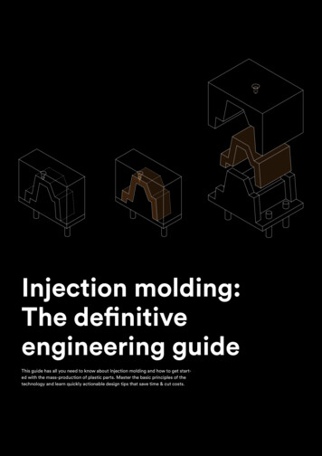
Injection molding:The definitiveengineering guideThis guide has all you need to know about Injection molding and how to get started with the mass-production of plastic parts. Master the basic principles of thetechnology and learn q uickly actionable design tips that save time & cut costs.1
Table of ContentsPart 1The Basics5.6.7.10.12.What is Injection molding?A brief history of InjectionmoldingInjection molding machines:How do they work?Benefits & limitations ofInjection moldingExamples of Injectionmolding productsPart 2Design forInjection Molding14.17.Common Injection moldingdefectsDesign Rules for InjectionMolding18.Dealing with undercuts20.Common design featuresPart 3Injection moldingmaterials24.26.2Injection Molding materialsSurface finishes & SPI standards
Part 4Cost reductiontips28.28.29.30.Cost drivers in Injection moldingTip #1: Stick to the straight-pullmoldTip #2: Fit multiple parts in onemoldTip #3: Minimize the part volumeby reducing the wall thicknessPart 5Start Injectionmolding32.34.35.36.Step 1: Start small & prototype fastStep 2 : Make a “pilot run”(500 - 10,000 parts)Step 3 : Scale up production(100,000 parts)Get an Injection moldingquote onlinePart 6Useful Resources38.Knowledge Base38.Other guides3
Part 1The BasicsWhat is a Injection molding? How does it work? What is it used for?In this section, we answer these questions and show you common examplesof injection molded parts to help you familiarize with the basic mechanics &applications of the technology.4
What is Injection molding?Injection molding is a formative manufacturing technology: to create a part,plastic is first melted and then injected into the cavity of a mold. When thematerial cools, it solidifies and takes the geometry (form) of the mold. Thepart is then ejected and the process starts over.This is a fundamentally different way of manufacturing compared to additive (3D printing) orsubtractive (CNC machining) technologies. Theflow and solidification of the material duringinjection have a significant impact on the keydesign restrictions for this technology - more onthis in below.Injection molding is widely used today for bothconsumer products and engineering applications.Almost every plastic item around you was manufactured using Injection molding. This is due tothe ability of the technology to produce identicalparts at very high volumes (typically, 1,000 to100,000 units) at a very low cost per part (typically, at 1-5 per unit).Compared to other technologies though, thestart-up costs of Injection molding are relativelyhigh, mainly due to the need for custom tooling.A mold can costs anywhere between 3,000 and 100,000 , depending on its complexity, mate-rial (aluminum or steel) and accuracy (prototype,pilot-run or full-scale production mold).All thermoplastic materials can be Injectionmolded. Some types of silicone and other thermoset resins are also compatible with the injection molding process. The most commonly usedmaterials in Injection molding are: Polypropylene (PP): 38% of globalproduction ABS: 27% of global production Polyethylene (PE): 15% of globalproduction Polystyrene (PS): 8% of globalproductionEven if we take into account all other possiblemanufacturing technologies, Injection molding with these four materials alone accountsfor more than 40% of all plastic parts producedglobally every year!5
A brief history of Injection moldingPlastics replace ivoryIn 1869, John Wesley Hyatt invented celluloid, thefirst practical artificial plastic intended to replaceivory for the production of. billiard balls! EarlyInjection molding machines used a barrel to heatup the plastic and a plunger to inject it to the mold.The revolutionary inventionIn the mid-1950s, the invention of the reciprocatingscrew single-handedly revolutionized the plasticsindustry. The reciprocating screw solved key issueswith uneven heating of the plastic that previoussystems faced, and opened up new horizons forthe mass production of plastic parts.Injection molding todayToday, injection molding is a 300 billion market.5 million metric tons of plastic parts are producedwith injection molding globally each year. Recently,the demand of biodegradable materials is increasing for environmental reasons.6
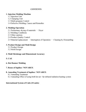
Injection molding machines:How do they work?An injection molding machine consists of three main parts: the injection unit,the mold - the heart of the whole process - and the c lamping/ejector unit.In this section, we examine the purpose of each of these systems andhow their basic operation mechanics affect the end-result of the Injection molding process.The injection unitThe purpose of the injection unit is to melt the raw plastic and guide it into themold. It consists of the hopper, the barrel, and the reciprocating screw. Theraw plastic material comes as pellets. In the hopper, the pellets can be mixedwith pigment or other additives (for example, glass fibers). This way, the colorand physical properties of the molded parts can be tailored to meet the specific needs of each application. Next, the material is fed into the barrel, whichcontains the r eciprocating screw.The screw performs two tasks: it carries the pellets towards the mold and atthe same time it compresses them. In fact, the shear forces caused by themovement of the screw produces 60% to 90% of the heat needed to meltthe plastic pellets. The rest is provided by the heater bands that are wrappedaround the barrel.Once enough melted plastic is in front of the screw, the ram plunges forwardand injects the material into the empty cavity of the mold (like a syringe). Thiswhole process happens in continous fashion, so filling the mold only takes afew seconds.7
The Anatomy of the MoldThe simplest mold - the straight-pull mold - consists of two halves: the cavityand the core. For more complex parts with ‘undercuts, side-action cores canalso be used that slide in and out of the part on an angle - more on side-actioncores & undercuts in a next section.The core and the cavity have different functions. The core is the half of themold that is closer to the injection system. It forms the cosmetic side of thepart (A-side) that requires a good visual appearance. The cavity is the backhalf of the mold and it forms the “hidden” functional side (B-side) that includesall structural elements of the part (ribs, bosses etc).The molds are usually CNC machined from aluminum (for 1,000 to 5,000 units)or tool steel (for 100,000 units). For low-production runs ( 100 units) themolds can even be 3D printed to expedite lead times.A part from the “negative” of the part, a mold has other features that supportthe injection process. For example, molds often include cooling channels thataccelerate the solidification process and vents that help evacuate the air fromthe empty mold.Interesting fact: About 50% of the typical Injection molding cycle is dedicateto part cooling and solidification. Minimizing the thickness of a design is keyto speed up this step & cuts costs.8
The Runner SystemThe melted plastic enters into the mold through the runner system. The runnersystem usually consists of three main sections: the sprue (the main channel),the runners (the guiding channels) and the gates (the entry points).Different gates types are suitable for different applications. The illustrationshows an edge gate, while the bricks below were manufactured using a hot tipgate - more on gate types here. The runner system is cut off from the part afterejection. This is the only m aterial waste in InjectionThe VestigeIn the point where the runner system connected with the part, a small imperfection is usually visible, called the vestige. If the presence of the vestige is notdesirable for asthetic purposes, then in can also be “ hidden” in the functionalB-side of the part.The Clamping & Ejection SystemOn the far side of an Injection molding machine, there is the clamping system.The clamping system has a dual purpose: it keeps the two parts of the moldtightly shut during injection and it pushes the part out of the mold after itopens. After the part is ejected, it falls on a conveyor belt or a bucket for storage and the cycle starts over again.Alignment of the different moving parts of the mold is never perfect though.This causes the creation of two common imperfections that are visible on almost every Injection molded part: Parting lines which are visible on the side of a part where the twohalves of the mold meet. They are caused by tiny misalignments andthe slightly rounded edges of the mold.Ejector (or witness) marks which are visible on the hidden B-side ofthe part. They are created because the ejector pins are slightlyprotruding above or indented below the surface of the mold.The image below shows the mold used to manufacture both sides of the casing for a remote controller. Quick quiz: try to locate the core (A-side), the cavity (B-side), the runner system, the ejector pins, the side-action core and the airvents on this mold.9
Benefits & Limitations ofInjection moldingInjection molding is an established manufacturing technology with a longhistory, but it is constantly being refined and improved with new technologicaladvancements. Below is a quick rundown of the key advantages and disadvantages of Injection molding to help you understand whether it is the rightsolution for your application.Benefits of Injection moldingHigh-volume manufacturing of plasticsInjection Molding is the most cost-competitive technology for manufacturing high volumes of identical plastic parts. Once the mold is created and themachine is set up, additional parts can be manufactured very fast and at a verylow cost.The recommended minimum production volume for injection molding is 500units. At this point economies of scale start to kick-in and the r elatively highinitial costs of tooling have a less prominent effect on the unit price.Wide range of materialsAlmost every thermoplastic material (and some thermosets and silicones) canbe injection molded. This gives a very wide range of available materials withdiverse physical properties to design with.Parts produced with Injection molding have very good physical properties.Their properties can be tailored by using additives (for example, glass fibres) or by mixing together different pellets (for instance, PC/ABS blends) toachieve the desired level of strength, stiffness or impact resistance.Very high productivityThe typical injection molding cycle last 15 to 60 seconds, depending on thesize of the part and the complexity of the mold. In comparison, CNC machining or 3D printing might require minutes to hours to produce the same geometry. Also, a single mold can accomodate multiple parts, further increasing theproduction capabillities of this manufacturing process.This means that hundreds (or even thousands) of identical parts can be produced every single hour.Great repeatability & tolerancesThe Injection molding process is highly repeatable and the produced parts areessentially identical. Some wear of course occurs to the mold over time, buta typical pilot-run aluminum mold will last 5,000 to 10,000 cycles, while fullscale production molds from tool steel can stand 100.000 cycles.10
Typically, Injection molding will produce parts with tolerances of 0.500 mm(0.020’’). Tighter tolerance down to 0.125 mm (0.005’’) are also feasible incertain circumstances. This level of accuracy is enough for most applicationsand comparable to both CNC machining and 3D printing.Excellent visual appearanceA key strength of Injection molding is that it can produce finished productsthat need little to no extra finishing. The surfaces of the mold can be polishedto a very high degree to create mirror-like parts. Or they can be bead blastedto c reate textured surfaces. The SPI standards dictate the level of finishingthat can be achieved.Get the finishing/material compatibility recommendations Limitations of Injection moldingHigh start-up costs for toolingThe main economic restriction in Injection molding in the high cost of tooling.Since a custom mold has to be made for each geometry, the start-up costsare very high. These are mainly related to the design and manufacturing of themold and typically varies between 5,000 and 100,000.For this reason, injection molding is only economically viable for productionslarger than 500 units.Design changes are costlyAfter a mold is manufactured, it is very expensive to modify it: design changesusually require the manufacture of a new mold from scratch. For this reason,correctly designing a part for Injection molding is very important.In Part 2, we list the most important design consideration you have to keep inmind while designing for Injection molding. It Part 5, we will also see how youcan mitigate the risk by creating physical prototypes of your parts.Longer lead times than other technologiesThe typical turnaround for injection molding varies between 6 to 10 weeks - 4to 6 weeks for manufacturing the mold, plus 2 to 4 more weeks for productionand shipping. If design changes are required to the model, something quitecommon, the turnaround time increases accordingly. In comparison, partsmade in a desktop 3D printer can be ready for delivery overnight, while industrial 3D printing systems have a typical lead time of 3-5 days. CNC machinedparts are typically delivered within 10 days or as fast as 5 days.11
Examples of Injectionmolding productsIf you look around you right now, you will see at least a few products that weremanufactured with Injection molding. You are probably looking at one rightnow actually: the casing of the device you are using to read this guide. To recognize them, look out for these three things: a parting line, witness marks onthe hidden side and a relatively uniform wall thickness throughout the part.We collected here some examples of common Injection molding products tohelp get a better understanding of what can be achieved with this manufacturing process.ToysLego bricks are one of the most recognisable examples of Injection moldedparts. They are manufactured using molds like the one in the picture, whichproduced 120 million lego bricks (that is 15 million cycles) before it was takenout of commission.The material used for Lego bricks is ABS due to its highimpact resistance and excellent moldabillity. Every single brick has been designed to perfection achieving tolerances down to 10 micro meters (or a tenthof a human hair). This is partly achieved by using the best design practiceswe will examine in the next section (uniform wall thickness, draft angles, ribs,embossed text etc).PackagingMany plastic packaging products are Injection molded. In fact, packaging isthe largest market for Injection molding. For example, bottle caps are Injectionmolded from Polypropylene. Polypropylene (PP) has excellent chemical resistance and is suitable to come in contact with food products.On bottle caps, you can also see all common Injection molding imperfections(parting line, ejector marks etc) and common design features (ribs, strippingundercuts etc).MiniaturesModel airplanes are another common example of Injection molded parts.The material used here is mostly Polystyrene (PS), for its low cost and ease ofmolding. What is interesting with model airplane kits is that they come withthe runner system still attached. So, you can see the path the melted plasticfollowed to fill the empty mold.12
AutomotiveAlmost every plastic component in the interior of a car was Injection molded.The three most common injection molding materials used in the automotive industry are Polypropylene (PP) for non-critical parts, PVC for its good weatherresistance and ABS for its high impact strength.More than half of the plastic parts of a car are made from one of these materials, including the bumpers, the interior body parts and the dashboardsElectricalThe enclosures of almost every mass-produced consumer electronic devicewas Injection molded. ABS and polystyrene (HDPE) are prefered here for theirexcellent impact resistance and good electrical insulation.HealthcareMany sterilizable and biocompatible materials are available for Injection molding. Medical grade silicone is one of the more popular materials in the medicalindustry. Silicone is a thermoset though, so special machinery and processcontrol are required, increasing the cost.For applications with less strict requirements other materials, like ABS,Polypropylene (PP) and Polyethylene (PE), are more common.13
Part 2Design for Injection moldingIn this section you will learn how to optimize your designs for Injection molding.Use the following guidelines to save time and reduce failures and learn how to create features that maximize the functionallity of your designs.14
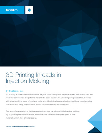
Common injectionmolding defectsMost defects in Injection molding are related with either the flow of the melted material or its non-uniform cooling rate during solidification.Here is a list of defects than an engineer should keep in mind while designinga part for Injection molding. In the next section, we will see how you can avoideach of them by following good design practices.WarpingWhen certain sections cool (and as a result shrink)faster than others, then the part can permanentlybend due to internal stresses. Parts with non-constant wall thickness are most prone to warping.Sink marksWhen interior of a part solidifies before its surface,a small recess in an otherwise flat surface mayappear, called a sink mark. Parts with thick walls orpoorly designed ribs are most prone to sinking.Drag marksAs the plastic shrinks, it applies pressure on themold. During ejection, the walls of the part willslide and scrape against the mold, which can resultto drag marks. Parts with vertical walls (and nodraft angle) are most prone to drag marks.15
Knit linesWhen two flows meet, small hair-like discolorations may develop. These knit lines affect theparts aesthetics, but also they generally decreasethe strength of the part. Parts with abrupt geometry changes or holes are more prone to knit lines.Short shotsTrapped air in the mold can inhibit the flow of thematerial during injection, resulting in an incomplete part. Good design can improve the flow ability of the melted plastic. Parts with very thinwalls or poorly designed ribs are more prone toshort shots.16
Design Rules forInjection MoldingLet’s see how these process restriction can be translated into actionable design guidelines. In the following sections, we summarize the most importantdesign rules to follow when designing parts for Injection molding, as well astips on how to design the most common features found in Injection moldedparts correctly.Use a constant wall thicknessRecommended thickness: 1 mm and 3 mmAlways design parts with the smallest possible (and constant) wall thickness, to avoid warping and sinking.If thicker sections are required, hollow them out and useribs to add stiffness instead. Keep in mind that each 10%increase in wall thickness provides approximately a 30%increase in stiffness.See material specific wall thickness recommendations Add smooth transitionsRecommended: 3 wall thickness differenceSometimes sections with different wall thickness cannotbe avoided. In these cases, use a chamfer or fillet to makethe transition as smooth as possible.Similarly, the baseof vertical features (like ribs, bosses, snap-fits) must alsoalways be rounded.Round all edgesInternal edges: 0.5 wall thicknessExternal edges: internal fillet wall thicknessThe constant wall thickness rule must also be applied tothe corners of the part. Add a fillet with a radius that isas large as possible to all internal and external edges.17
Add draft anglesRecommended minimum: 2 Add a draft to all vertical walls to make the ejectionof the part easier and avoid drag marks. If they servea functional purpose, external walls may be leftundrafted (see Lego bricks). Increase the draft angleabove the recommended in these cases: For parts taller than 50 mm, increase the draftby 1 for every 25 mmFor parts with a textured finish, increase thedraft by an extra 1 -2 Dealing with undercutsAn important aspect to consider while designing parts for Injection moldingare undercuts.Undercuts in Injection molding are part features that cannotbe manufactured with a simple two-part mold, because materialis in the way while the mold opens or during ejection.The teeth of a thread or the hook of a snap-fit joint are examples of undercuts.Here are some simple solutions to help you deal with undercuts:Moving the parting lineThe simplest way to deal with an undercut is to movethe parting line of the mold to intersect with it.This solution is suitable for many designs withundercuts on an external surface. Don’t forget toadjust the draft angles accordingly.Using a shut-offAnother way to deal with undercuts is to removematerial from under or above the problematic area.This way the undercut is eliminated as the wholepart can be directly supported by the mold.Shut-offs are a useful trick to deal with undercuts oninternal regions of the part (for snap-fits) or on thesides of the part (for holes or handles).18
Stripping undercutsIf the part is flexible enough, then deforming overthe mold during ejection is an option. Strippingundercuts are used for internal features, such asthe threads of bottle caps. Use these guidelines todesign stripping undercuts: Select a flexible material - such as PP, PEor Nylon (PA)The height of the undercut should be 5% thediameter of the holeUse a lead angle of 30 to 45 Side-action coresWhen none of the above solutions are viable, thencores can be used that slide out of the part fromthe side before it is ejected. Side-action coresshould be used sparingly as they add complexityand increase the overall cost of a mold by 15% to30%. Follow these guidelines when designing aside-action core: The core must move in a direction parallel tothe parting lineDraft angles must be added as usual19
Common design featuresWe list below practical guidelines on how to design the most common featuresencountered in Injection molded parts. Use them to improve the functionalityof your designs, while still complying with the basic design rules.Read the full design guidelines for Injection molding RibsWhen the even the maximum recommended wall thickness is not enough to meet the functional requirementsof a part, ribs can be used to improve its stiffness.When designing ribs: Use a thickness equal to 0.5 main wallthicknessDefine a height smaller than 3 rib thicknessUse a base fillet with radius greater then¼ rib thicknessAdd a draft angle of at least 0.25 - 0.5 Add a min. distance between ribs & walls of4 rib thicknessBossesBosses are used as points of attachment or fastening(in conjuction with self-tapping screws or threadedinserts). Think of bosses as circular ribs - the same general design guideline apply. Consider also the following: Avoid designing bosses that merge into main wallsSupport bosses with ribs or connect them to amain wallFor bosses with inserts: Use an outer diameter equal to 2 the insert’snominal sizeSnap-fit jointsSnap-fits are an economical and rapid way of joiningtwo parts without fasteners or tools. When designingsnap-fits for Injection molding: Add a draft to the side-walls of the snap-fitUse a thickness of 0.5 main wall thicknessAdjust the width & length to control thedeflection & forceThink how to deal with the created undercutFor detailed guidelines, refer to this article from MIT.20
Living hingesLiving hinges are thin sections of plastic that connecttwo segments of a part and allow it to flex and bend.Here are some tips to help design a living hinge: Select a flexible material (for example PP, PEor Nylon)Design hinges with a thickness between 0.20and 0.35 mmUse shoulders with a thickness equal thethickness of the main wallAdd as large fillets as possibleFor detailed guidelines, please refer to this MIT guide.Crush ribsCrush ribs deform and create friction between the partand the inserted component, securing it in place.They are a fast and inexpensive method of incorporating bearings or other inserts in your designs. For highend applications, consider using a press fit instead.When designing crush ribs: Use three circular ribs with a 2 mm radiusAdd a min. overlap of 0.25 mm between the riband the insertAdd draft to the hole but do not draft the ribsThreadsThreads can be added directly to the molded part design, but introduce u ndercuts. Alternatively, threadedinserts can be used. Follow these guidelines when youdesign parts with threads: Add a 0.8 mm relief at the edges of the threadUse a thread with a pitch greater than 0.8 mm(32 threads per inch)Prefer using a trapezoidal or buttress threadTo deal with the created undercuts: For internal threads, consider using strippingundercutsFor external threads, place them along theparting line21
Lettering & symbolsText, logos and other symbols can be engraved orembossed on the surface of Injection molded parts.Here are some tips while adding text: Prefer embossing instead of engravingAlign the text perpendicular to the parting lineUse a height (or depth) greater than 0.5 mmUse a font with uniform letter thicknessThe font size should be at least 20 pointsTolerancesInjection molding typically produces parts with tolerances of 0.500 mm (0.020’’). Tighter tolerancesare feasible in certain circumstances (down to 0.125 mm - and even 0.025 mm), but they increasethe cost drastically.For small production runs ( 10,000 units), consider using a secondary operation (such as drilling) toimprove accuracy. This ensures the correct interference of the part with other components or inserts(for example, when using press fits).22
Part 3Injection moldingmaterialsInjection molding is compatible with a very wide range of plastics. In thissection, you will learn more about the key characteristics of the most popular materials. We will also visit the standard surface finishes that can beapplied to Injection molded parts.2323
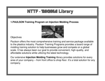
Injection molding materialsAll thermoplastics can be injection molded. Some thermosets and liquidsilicones are also compatible with the injection molding process. They canbe also reinforced with fibers, rubber particles, minerals or flame retardantagents to modify their physical properties. For example Fiberglass can bemixed with the pellets at ratios of 10%, 15% or 30% resulting in parts with higher stiffness.Polypropylene (PP)The most common Injection molding plastic. Excellentchemical resistance. Food-safe grades available. Notsuitable for mechanical applications.ABSCommon thermoplastic with high impact resistance,low-cost & low density. Vulnerable to solvents.Polyethylene (PE)Lightweight thermoplastic with good impact strength &weather resistance. Suitable for outdoor applications.Polystyrene (PS)The Injection molding plastic with the lowest cost.Food-safe grades available. Not suitable for mechanical applications.Polyurethane (PU)Thermoplastic with high impact strength and goodmechanical properties & hardness. Suitable for molding parts with thick walls.Nylon (PA 6)Engineering thermoplastic with excellent mechanicalproperties and high chemical & abrasion resistance.Susceptible to moisture.24
Polycarbonate (PC)The plastic with the highest impact strength. Highthermal resistance, weather resistance & toughness.Can be colored or transparent.PC/ABSBlend of two thermoplastics resulting in high impactstrength, excellent thermal stability, and high stiffness.Vulnerable to solvents.POM (Acetal/Delrin)Engineering thermoplastic with high strength, stiffness& moisture resistance and self-lubricating properties.Relatively prone to warping.PEEKHigh-performance engineering thermoplastic withexcellent strength and thermal & chemical resistance.Used to replace metal parts.Silicone rubberThermoset with excellent heat & chemical resistanceand customizable shore hardness. Food-safe and medical grade available.25
Surface finishes & SPI standardsInjection molded parts are not usually post-processed, but the mold itselfcan be finished to various degrees. This way aesthetic needs (for example, amirror-like or matte surface) or technical requirements (for example, specificsurface roughness or tolerances) can be achieved.The Society of Plastics Industry (SPI) several standard finishing proceduresthat result in different part surface finishes.FinishDescriptionApplicationGlossy finishSPI standard: A-1, A-2, A-3The mold is smoothed and then polished with a diamond buff, resulting inparts with a mirror-like finish.Suitable for parts that need the smoothest surface finish for cosmetic or functional purposes (Ra 0.10 μm)Semi-gloss finishSPI standard: B-1, B-2, B-3The mold is smoothed with fine gritsandpaper, resulting in parts with a finesurface finish.Suitable for parts that require a goodvisual appearance, but not a highglossy look.Matte finishSPI standard: C-1, C-2, C-3The mold is smoothed using fine stonepowder, removing all machining marks.Suitable for parts with low aesthetic requirements, but when machining marksare not acceptable.Textured finishSPI standard: D-1, D-2, D-3The mold is first smoothed with finestone powder and then sandblasted,resulting in a textured surface.Suitable for parts that require a satin ormatte textured surface finish.As-machined finishThe mold is finished to the machinist’sdiscretion. Tool marks may be visible.Suitable for non-cosmetic, industrialparts or hidden components.See a detailed description of the SPI standards & their compatibility with each material 26
Part 4Cost reduction tipsLearn more about the main cost drivers in Injection molding andthree actionable design tips that will help reduce costs you keepyour project on budget.2727
Cost drivers in Injection moldingThe main cost drivers in Injection molding are: Tooling costs determined by the total cost of
An injection molding machine consists of three main parts: the injection unit, the mold - the heart of the whole process - and the clamping/ejector unit. In this section, we examine the purpose of each of these systems and how their basic operation mechanics affect the end-result of the Injection mdinol g opc. ress The injection unit