Transcription
View metadata, citation and similar papers at core.ac.ukbrought to you byCOREprovided by TheseusSimulation and Design of a plastic injection MoldA Joint mold for credit card and USB holderSamson TeklehaimanotDegree ThesisPTE20111
2
DEGREE THESISArcadaDegreeProgramme:Plastic isor (Arcada):9639Samson TeklehaimanotSimulation and Design of a plastic injection moldMarko VohoCommissioned by:Abstract:Injection molding is one of the most important processes in the plastic manufacturingindustry. More than one-third of all plastic materials are injection molded, And the moldis one of the main components in the injection molding process. The aim of thisengineering thesis is to show detailed steps on how to design a complete mold and usingthe simulation software to analyze the material flow and defects in the product. Theproduct design for this project is a joint credit card and USB flash drive holder. Whatmakes this product unique from others is that it contains both functions together whereasmost of the products in the market today don’t contain the same dual application.The design of this product and the mold were made by the designing analysis softwareSolid edge ST2 software, Which is then simulated by the use of Mold Flow.Keywords:Numberof pages:Language:Date ofacceptance:Mold design, credit-card holder, USB holder, Mold flowsimulation.53English3
AcknowledgementsI owe sincere and earnest thankfulness to my advisor Marko Voho for the support, guidance andpatience he showed me throughout my Thesis writing.I would also like to show my gratitude to Mathew Vihtonen, Mariann Holmberg and BadalDurbo karis for their support in the study years.It is a great pleasure to thank all my friends and classmates who helped me write my thesissuccessfully by providing me great information resources.I am sincerely and heartily grateful to my mother Dr Wubayehu Berhane and Brother Fitsumwho boosted me morally. I am sure this would have not been possible without their help.4
Table of ContentsAcknowledgements . 4List of Figures . 7List of Tables . 81.Introduction . 91.1.Background . 91.2.Objective . 101.3 Abbreviation . 112.Literature Survey . 122.1.The injection molding . 122.1.1.The injection molding process . 132.2 Injection molding machine components . 152.2.1 Hopper . 152.2.2 The barrel . 152.2.3 The Screw . 152.2.4 The Nozzle . 162.3 Material Analysis . 162.4 Some problems associated with Injection molding . 202.5 Plastic Injection Molds . 222.5.1Plastic Injection mold components & their function . 232.5.2 Classification of molds . 232.6 Gates . 272.7 Sprue. 292.8 Runner systems . 302.9 Ejection System . 302.10 Cooling System . 312.10.1 Cooling Layout . 312.11. Venting . 312.12 Injection mold steel selection . 325
3.Methods and Result . 343.1 Software assistance . 343.2 Product Design . 343.3 Mold Flow analysis . 353.3.1 Meshing . 363.3.2. Meshing Steps. 363.3.3. Mesh Statistics . 373.3.4. Fill Analysis . 393.4 Mold Design . 413.4.1 Cavity plate and Core plate . 444.Conclusions . 485.Reference . 49APPENDIX . 526
List of FiguresFigure 1 : Injection Molding Machine . 12Figure 2 : Injection molding cycle. 13Figure 3 : Typical pressure and temperature cycle of injection molding. 15Figure 4 Different Zones of the Screw . 16Figure 5 Classification of polymers . 17Figure 6 Thermoset Structure. 18Figure 7 Elastomer Structure . 19Figure 8 Crystalline structure . 19Figure 9 Amorphous structure. 20Figure 10 : Impression of a standard injection mold. 22Figure 11 : Two plate cold runner mold . 24Figure 12 : Three plate cold runner mold . 25Figure 13 : Cross-section of a basic hot runner system. 26Figure 14 : Insulated runner mold . 27Figure 15 : Sprue gate . 28Figure 16 : Edge gate . 28Figure 17 : Tab gate . 29Figure 18 : Different types of cooling layouts . 31Figure 19 : Credit card and USB holder product design . 35Figure 20 – Results of the mesh analysis. 37Figure 21 – Mesh Statistics for analysis . 38Figure 22- Fill analysis . 40Figure 23 Section view of the mold . 42Figure 24 Mold detailed part list . 43Figure 25 Technical drawing of the cavity plate. 45Figure 26 Technical drawing of the Core plate . 46Figure 27 Exploded view of the mold . 477
List of TablesTable 1 Common thermoplastic groups. 17Table 2 : Injection molding problems and solutions . 21Table 3 : Mold components and their functions . 23Table 4 : Comparison between insulated runner and cold runner mold . 26Table 5 : Vent depth of some materials . 32Table 6. Fill analysis Results . 408
1. Introduction1.1.BackgroundThe injection molding has seen steady growth since its beginnings in the late 1800's. Thetechnique has evolved from the production of the simple things like combs and buttons to majorconsumer, industrial, medical, and aerospace products.The invention of an injection molding machine was achieved by John Wesley who injected hotcelluloid into a mold which resulted in billiard balls which were used as a replacement for ivorywhich was based on the pressure die casting technique for metals. [7] The industry progressedslowly over the years, producing products such as collar stays, buttons, and hair combs. Theindustry expanded rapidly in the 1940s because World War II created a huge demand forinexpensive, mass-produced products. In 1946, American inventor James Watson Hendry builtthe first screw injection molding machine, which allowed much more precise control over thespeed of injection and the quality of articles produced. This machine also allowed material to bemixed before injection, so that colored or recycled plastic could be added to virgin material andmixed thoroughly before being injected. [20]The main concept of plastic molding is placing a polymer in a molten state into the mold cavitySo that the polymer can take the required shape with the help of varying temperature andpressure. There are different ways of molding a plastic some of them are blow molding, Injectionmolding, rotational molding and compression molding. Each technique has their own advantagesin the manufacturing of specific item.[1]9
1.2.ObjectiveThese are objectives of the thesis To prepare a product design for ’’ a joint credit card & USB holder ’’ by using designanalysis softwareTo design and test the plastic injection mold for the specific productUsing Mold Flow to simulate the polymer flow and finding out maximum clamp forceand Fill time.10
1.3 Abbreviation1) LDPE - Low Density Polyethylene2) HDPE - High Density Polyethylene3) PP - Polypropylene4) PS - Polysterene5) ABS - Acrylonitrile-Butadiene-Styrene6) PVC - Polyvinyl Chloride7)PMMA - Polymethylmethacrylate8)PVDF - Polyvinylidene Fluoride9) PET - Polyethylene Terephtalate10) PI - Polyimide11) PC - Polycarbonate12) PES–Polyethersulfone13) Tg – Glass transition temprature11
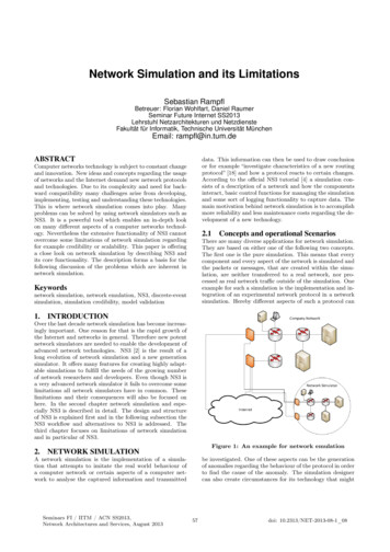
2. Literature Survey2.1.The injection moldingInjection molding is a method of forming a plastic product from powdered thermoplastics byfeeding the material through the machine component called the hopper to a heated chamberin order to make it soft and force the material into the mold by the use of the screw. In thiswhole process pressure should be constant till the material is hardened and is ready to beremoved from the mold. This is the most common and preferable way of producing a plasticproducts with any complexity and size. [1]Injection molding permits mass production netshape manufacturing of high precision, threedimensional of plastic parts. [3]Figure 1 : Injection Molding Machine [4]12
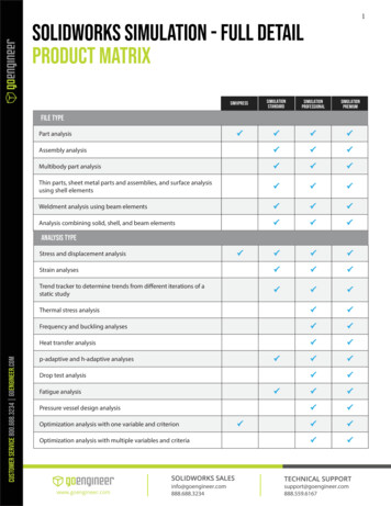
2.1.1. The injection molding processThe injection molding process stages starts with the feeding of a polymer through hopper tobarrel which is then heated with the sufficient temprature to make it flow , then the moltenplastic which was melted will be injected under high pressure into the mold the process iscommonly known as Injection, After injection pressure will be applied to both platens of theinjection molding machine(moving and fixed platens) inorder to hold the mold tool togetherafterwards the product is set to cool which helps it in the solidification process. After the productgets its shape the two platens will move away from eachother inorder to separate the mold toolwhich is known as mold opening and finally the molded product is ejected or removed from themold. And the process will repeat itself.Figure 2 : Injection molding cycle [5]13
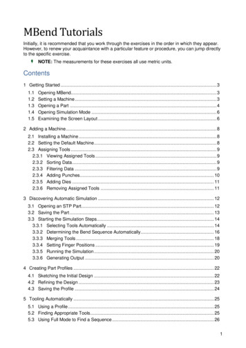
The molding cycle starts with the retraction of the ejector plate, followed by closing ofthe mold. The injection unit melts the polymer resin and injects the polymer melt into the mold.The ram fed injection molding machine uses a hydraulically operated plunger to push the plasticthrough a heated region. The melt converges at a nozzle and is injected into the mold.The melt is forced into the mold in two or three stages: Stage 1: Fill stageo During this stage, the mold cavities are filled with molten resin. As thematerial is forced forward, it passes over a spreader, or torpedo, within thebarrel, which causes mixing. This stage is determined by an injection velocity(rate), a pressure, and a time. Injection velocity is the rate at which the plungermoves forward. Stage 2: Pack stageo As the melt enters the mold, it cools and introduces shrinkage. The pack stageis necessary to force more melt into the mold to compensate for shrinkage. Stage 3: Hold stageo When no more material can be forced into the mold, melt can still leak backthrough the gate. The hold stage applies forces against the material in thecavity until the gate freezes to prevent leaking of the melt. In some machines,pack and hold are combined into a single second or holding stage.Each stage is governed by a particular pressure and time duration, as can be seen in Figure 4:Once the mold is filled and packed and the gate has cooled, the injection molding machineswitches to the cooling stage. The amount of cooling is determined by the cooling time. Afterthe cycle is complete and before the next cycle can be run, the machine must be purged perdirections in the manual. [9]14
Figure 3 : Typical pressure and temperature cycle of injection molding [9]2.2 Injection molding machine componentsThe injection molding machine consists of the hopper, screw, the barrel and the injection nozzle.2.2.1 HopperIn the molding process the plastic materials are supplied in the form of small pellets. The hopperfunctions as the holder of these pellets. The pellets are then gravity fed from the hopper to thebarrel.2.2.2 The barrelThe main use of the barrel is to give support for the screw. The Barrel consists of heater bandswhich function as a temperature recorder for each section of the barrel.2.2.3 The ScrewAlso known as the reciprocating screw is used in compressing, melting and conveying the plasticmaterial. The Screw consists of three zones – The feeding zone,theTransition zone and the15
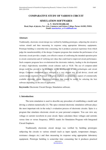
metering zone. In the feeding zone there will be no change to the plastic materials and they willremain pellets and will be transferred to the next zone which is the transition zone , In this zonemelting of the pellets will occur and the molten plastics will be transferred to the next zonewhich is the metering zone , In this zone the molten material will be ready for injection.Figure 4 Different Zones of the Screw [21]2.2.4 The NozzleThe main function of the nozzle is in connecting the barrel to the sprue bushing which in turnforms a seal between the mold and the barrel. It’s essential that the nozzle temperature should beset to the materials melt temperature.[21]2.3 Material AnalysisPolymers play huge role in the injection molding process; most polymers are classified into threegroups - thermoplastics, thermosets, and elastomers. The thermoplastics can be divided into twotypes - those that are crystalline and those that are amorphous.[25]16
rsAmorphousFigure 5 Classification of polymersPolymers are the assembly of small organic repeating molecules called monomers. Properties ofmonomers include high resistivity to chemicals and can also be thermal and electrical insulators.Thermoplastic materials generally soften when they are exposed to heat and return to theirprevious condition when cooled this is because there molecules are held by a weakintermolecular force. The property where they are repeatedly melted and cooled gives them asimilar property as that of metals. The major thermoplastic groups are all produced by chainpolymerization. Due to their recyclable property they are used in a wide range of applicationssuch as Food packaging, insulation, automobile bumpers and credit card holders.Table 1 Common thermoplastic groupsThemoplastic GroupsCommon examplesPolyolefinesLDPE , HDPE, PPStyrenicsPS, rsPETPolyamides (Nylons)Nylon 6 , Nylon 6617
PolyimidesPIPolyethersPCSulphur containing polymersPESThermosetting plastics or simply known as thermosets solidifies irreversibily when heated.Thermosets cannot be reshaped by heating. Thermosets are usually three-dimensional networkedpolymers in which there is a high degree of cross-linking between polymer chains. The rigidityof the material is caused by cross-linking which restricts the motion of the chains. Thermosetsare strong and durable. They primarily are used in automobiles and construction. They also areused to make toys, varnishes, boat hulls and glues.Figure 6 Thermoset Structure [23]Elastomers are rubbery polymers that can be stretched easily to several times and which rapidlyreturn to their original dimensions when the applied stress is released.Elastomers are crosslinked, but have a low cross-link density. The polymer chains still have some freedom to move,but are prevented from permanently moving relative to each other by the cross-links.[23] Tostretch, the polymer chains must not be part of a rigid solid - either a glass or a crystal. Anelastomer must be above its glass transition temperature, Tg, and have a low degreeof crystallinity. Many elastic materials including rubber bands are made of elastomers.18
Figure 7 Elastomer Structure [23]Highly crystalline polymers have properties like high rigidity, high melting point and are lessaffected by solvent penetration. The higher the crytallinity of polymers, the stronger the polymerbut there impact resistance will be weakened. Small molecules and ions form a threedimensional lattice with an extended regular structure that makes large crystals possible.Figure 8 Crystalline structure [23]Polymers which cannot pack together regularly to form crystals and polymer chains withirregular groups are known as Amorphous. These polymers are made of randomly coiled andentangled chains like spaghetti. Amorphous polymers are softer, have lower melting points, andare penetrated more by solvents than are their crystalline counterparts. [23]19
Figure 9 Amorphous structure [23]2.4 Some problems associated with Injection moldingIt’s a common coincidence that defects in injection molding arise from the mold designimperfection and inappropriate material compounding.Mold seal clearance, inappropriate clamping force and melting temperature along with nonuniform setting times play the major role in lowering the product quality. Besides, the usage oflow grade polymer with inappropriate mass–mass ratio would also be a non-conformance in theproduction of a quality product.The following below are some of the problems that might arise in the production line. Theseresearches are done by ExxonMobil Chemical Company for the material Polypropylene(PP).This list will highlight problem areas of Injection Molding and a typical cause and methodof resolving that problem.20
Table 2 : Injection molding problems and solutions [6]ProblemCausePossible solutionSink marks-Part is under filled-increase shot size-increase cavity or hold pressure-Reduce fill rate-Open gatesImproper gate location or designVoids-Part is under filled or has -poor ventingexcessive shrinkage-improper gate location-Injection rate too highShrinkage-Volume decreases as plastic -increase hold timecools-improperly balanced cavity and-Insufficient cooling timecore temperature-Runners or gates too smallFlash-insufficient clamping force- increase clamp force--clean mold surfaces-change gate locationsBurning-Compressed air in the mold -decrease peak cavity pressuredegrades the resin-clean vents , increase the size ornumber of vents-reduce melt temperatureWarp-non uniform stress due to -Part ejected too hot ( so increaseexcessive orientationcycle time)-decrease injection fill rate-Flow too long , Insufficient gate-change gate locationBrittle parts-Excessive orientation-increase injection fill rate-improper design-increase melt temperature-degradation of resin-design properly , adequate radiiat corners, notches or threads21
2.5 Plastic Injection MoldsA mold is simply a machined steel plate with cavities into which plastic resin is injected to forma part. [13] A mold consists of two halves into which the impression of the part product to bemolded is cut. The mating surfaces of the molded halves are accurately machined so that noleakage of plastic can occur at the split line. If leakage occurs it would be expensive to remove.[7]Figure 10 : Impression of a standard injection mold [8]22
2.5.1Plastic Injection mold components & their functionThe following table below gives a bird’s eye view of a complete mold with each componentandtheir respective functions.Table 3 : Mold components and their functionsMold ComponentMold baseFunctionsHold cavities in a fixed position relative tomachine nozzleGuide PinsMaintain proper alignments of two halves of themoldSprue bushingGatesRunnersCavity and CoreProvides means of entry into mold interiorControl flow to cavitiesConvey molten plastics from sprue into cavitiesControl size, shape and surface texture of moldedarticleWater channelsControl temperature of mold surfaces to coolplastic to rigid stateVentsEjector mechanism(pins, blades, stripper plate)Ejector return pinsFacilitates escaping of trapped air and gasEject rigid molded article from cavity or coreReturn ejector pins to retracted position as moldcloses for next cycle2.5.2. Classification of moldsWide range of molds can be classified into these 4categories:1) The cold runner two plate molds2) The cold runner three plate molds3) The hot runner molds4) The insulated runnermoldsThe cold runner mold is the simplest type of mold which consists two plates, the cavity and thecore. The main reason for being called two plate molds is that they consist of one parting line23
and the mold splits into two halves. This makes it ideal to place the runner system on the partingline.[9]Figure 11 : Two plate cold runner mold [17]The cold runner three plate molds consist of three plates - The stationary plate, The middle plateand The movable plate. The stationary plate also known as the runner plate is where the sprueand half of the runner are placed. The middle plate commonly known as the cavity plate as thefigure below clearly indicates it consists of half of the runner and also the gate. And theremaining plate is the movable plate also named the force plate contains the product producedfrom the mold and the ejector system which is applicable in the removal of the molded part. Themain reason for using this mold is because of their flexibility in gating locations.[9]24
Figure 12 : Three plate cold runner mold [17]The main difference between the two molds is that the three plate mold has two parting planes,and the mold splits sections every time the part is ejected.In a hot runner mold, the runner is situated internally in the mold and kept a temperature abovethe melting point of the plastic. Runner scrap is reduced or eliminated. The major disadvantageof a hot runner is that it is much more expensive than a cold runner, it requires costlymaintenance, and requires more skill to operate. Color changes with hot runner molds can bedifficult, since it is virtually impossible to remove all of the plastic from an internal runnersystem.Hot runners have many advantages to name a few: - They can completely eliminate runner scrapthis is helpful so there are no runners to sort from the parts, and no runners to throw away orregrind. Hot runners are popular in high production parts, especially with a lot of cavities.25
Figure 13 : Cross-section of a basic hot runner system [8]Insulated runner molds have oversized passages formed in the mold plate. The passages are ofsufficient size that, under conditions of operation, the insulated effect of the plastic (frozen onthe runner wall) combined with the heat applied with each shot maintains an open, molten flowpath. The insulated runner system should be designed so that while the runner volume does notexceed the cavity volume all of the molten material in the runner is injected into the cavityduring each shot. This helps prevent excessive build-up of the insulating skin and minimizes anydrop in melt temperature.Advantages and Disadvantages of Insulated runner molds compared to cold runner mold can befound in the table below.Table 4 : Comparison between insulated runner and cold runner moldAdvantagesReduction in material shearFaster cycle timesElimination of runner scrapDecreased tool wearImproved part finishShorter Cycle timesDisadvantagesMore complex tool designHigher tool costHigher maintenance costStartup procedure is more difficultpossible thermal degradation of materialColor change is considered difficult26
Figure 14 : Insulated runner mold [8]2.6 GatesGates are a transition zone between the runner system and the cavity. The location of gates is ofgreat importance for the properties and appearance of the finished part. The melt should fill theentire cavity quickly and evenly. For gate design the following points should be considered:-Locate the gate at the thickest section-Note gate marks for aesthetic reasons-Avoid jetting by modifying gate dimensions or position-Balance flow paths to ensure uniform filling and packing-Prevent weld lines or direct to less critical sections-Minimize entrapped air to eliminate burn marks-Avoid areas subject to impact or mechanical stress-Place for ease of de-gatingCommonly Used gate types include Sprue gate, Edge gate, Tab gate and Fan gateSprue gate is recommended for single cavity molds or for parts requiring symmetrical filling.This type of gate is suitable for thick sections because holding pressure is more effective. A short27
sprue is favored, enabling rapid mold filling and low-pressure losses. A cold slug well should beincluded opposite the gate. The disadvantage of using this type of gate is the gate mark left onthe part surface after the runner (or sprue) is trimmed off. Freeze-off is controlled by the partthickness rather than determined the gate thickness. Typically, the part shrinkage near the spruegate will be low; shrinkage in the sprue gate will be high. This results in high tensile stressesnear the gate.Figure 15 : Sprue gate [8]The edge or side gate is suitable for medium and thick sections and can be used on multi-cavitytwo plate tools. The gate is located on the parting line and the part fills from the side, top orbottom.Figure 16 : Edge gate [8]28
A tab gate is typically employed for flat and thin parts, to reduce the shear str
the mold. The injection unit melts the polymer resin and injects the polymer melt into the mold. The ram fed injection molding machine uses a hydraulically operated plunger to push the plastic through a heated region. The melt converges at a nozzle and is injected into the mold. The melt is forced into the mold in two or three stages: