Transcription
Paper ID #14644The Design Projects for the Simulation-Based Design CourseDr. Xiaobin Le P.E., Wentworth Institute of TechnologyAssociate professor, Ph.D, PE., Department of Mechanical Engineering and Technology, Wentworth Institute of Technology, Boston, MA 02115, Phone: 617-989-4223, Email: Lex@wit.edu, Specializationin Computer Aided Design, Mechanical Design, Finite Element Analysis, Fatigue Design and Solid MechanicsProf. Ali Reza Moazed, Wentworth Institute of TechnologyAli R. Moazed is a Professor in the Mechanical Engineering and Technology department at WentworthInstitute of Technology. In addition to twenty five years of industrial and consulting experience, he hastaught mechanical engineering courses full or part-time prior to joining Wentworth in 2001. At Wentworth, he teaches design related courses in the solid mechanics area. He believes in teaching from theperspective of a practicing academician by bringing into the classroom topics related to the practice ofengineering, along with the latest pedagogical tools.His expertise is in the area of Applied Finite Element Analysis (FEA) and as an engineering consultant,he provides FEA services to the Utility, Industrial, and Commercial clients nationwide. These servicesinclude design analysis, design verification, design modification, design optimization, and failure analysis.He is a registered professional engineer in states of Massachusetts and California.Prof. Anthony William Duva P.E. P.E., Wentworth Institute of TechnologyAnthony W. Duva An Associate Professor in the Mechanical Engineering and Technology Departmentat Wentworth Institute of Technology since 2001 with 14 years of prior full time industrial experience.He has worked in the design of various technologies from advanced underwater and ultrahigh altitudepropulsion systems to automated manufacturing equipment. His interests include advanced thermal andmechanical system design for green power generation.c American Society for Engineering Education, 2016
The Design Projects for the Simulation Based Design CourseAbstractThe course MECH625-simulation-based design in our program was mainly to conduct FEA(Finite Element Analysis) on components and assemblies to provide stress/strain information.Through our program assessment, it was found that students who performed excellently in theprevious MECH625 course had some difficulties incorporating FEA simulation correctly andefficiently on their senior design projects. In fall 2014, we decided to modify the course andcreated two projects to improve student skills in running FEA simulations on projects. The firstproject was an individual project in which students were mainly asked to use different simulationskills to run FEA simulations and then compare the FEA results with the theoretical handcalculation results. The second project was a team design project which was to baseline thestructural strength of a real device and then redesign it according to the design specifications.During the successful implementation of the two projects in spring semester 2015, the majorityof students had strong positive feedbacks about the projects based on the data collected bothdirectly and indirectly. This paper will provide details of the two projects, their implementationand the analyzed results of a student survey.1. IntroductionOne of the main outcomes of any mechanical engineering program is that mechanicalengineering students are able to develop product designs within specified constraints. One ofthe main tasks for mechanical engineering graduates in the industry is to design new products.This is also reflected in the ABET a-k criteria, specifically item c of the ABET a-k criteria,which is “c. ability to design a system, component, or process to meet desired needs.” Therefore,product design is at the heart of any mechanical engineering major and demands attention [1]. Inorder to conduct successful product designs, the stress/strain of components under loadings mustbe fully explored and known. However, stress/strain of components/ assemblies withcomplicated geometries and loading, which typically encounter in industry, seldom have anexplicit theoretical solution.FEA (Finite Element Analysis) simulation is a numerical technique that simulates physicalbehaviors by means of a numerical process based on piecewise polynomial interpolation appliedto the controlling fundamental equations. Typically, these equations are partial differentialequations with specific sets of boundary conditions used in their solutions [2,3,4]. FEA simulationsoftware for stress/strain analysis is a digital version of the partial differential equation stress/strain theories [5]. FEA simulation has been used extensively during the past thirty years in theindustry and is now a standard engineering tool for both analysis and design.A typical FEA course has been usually, in the past, reserved for graduate students who had amore rigorous mathematical education than undergraduate students and focused on the FEAtheory. Because earlier versions of FEA software had poor pre-processing and post-processingcapabilities, the user might be required to use sophisticated skills for manually creating meshingand describing boundary conditions. However, powerful personal computers have enabled FEA
simulation software to evolve with powerful pre-processing, meshing, ease setting of boundaryconditions (loading and restraints) and sophisticated post-processing capabilities. In summary,current commercial FEA simulation software is “ease of use” [1,6,7] and has transformed FEAsimulation from a specialized tool into an essential daily-used tool in both industry andacademics [6]. Today, an FEA simulation course has become a necessity and is offered in mostcolleges in today’s undergraduate mechanical engineering programs [6,7,8,9].The MECH625-simulation-based design in our mechanical engineering program was firstoffered in spring semester 2014 and approached in the traditional method. It was a requiredcourse for a mechanical engineering major. The format of the course utilized a combination oflecturing and labs with homework assignments, including the use of FEA simulation for both 3Dcomponents and assemblies. This course provided fundamental concepts of the FEA method andwas focused on how to use SolidWorks Simulation for mechanical design.Through our program assessment, it was found that students who performed excellently in thetraditional FEA course had some difficulties incorporating FEA simulation correctly andefficiently on their senior design projects. The main difficulties they had were: (1) unable toprepare suitable models for meshing and FEA simulation and (2) unable to define reasonableboundary conditions. There were lots of decision-making activities between their senior designprojects and the suitable FEA analysis cases. However, they lacked this experience in theircourse work. If the main objective of the FEA course is stress/strain simulation for productdesigns, faculty discussion of the assessment results concluded the best way to learn andimplement FEA simulation should be through design projects. A project-based curriculum wasimplemented in the 2015 spring semester, which added two design projects in the FEA course.At the end of the 2015 spring semester, student surveys were administered to evaluate the changeand feedback was extremely positive. Some comments from students’ report will be alsoaddressed. This paper will describe the course modification and the implemented projects.2. Background and key contents of the MECH625-simulated-based design courseThe MECH625-simulation-based design is a senior-level FEA simulation course, which is one ofthe core technical courses in the design thread of our mechanical engineering programcurriculum. The design thread in our program includes courses in engineering design,engineering graphics, engineering statics, mechanics of materials, design of machine elements,material science, mechanical vibration, simulation-based design and senior design project. TheMECH625 is a bridge course between theories of the mechanical design process and theirindustrial implementation.In our school, every mechanical engineering student has been issued a laptop with theSolidWorks software package. We have 1000 educational licenses which allow our mechanicalstudents to fully access every module of SolidWorks suit. Before students enrolled inMECH625-simulation-based design in their senior year, they had learned how to use SolidWorksfor creating models/assemblies, generating drawings and had introductory experience with theSolidWorks simulation as they progressed through the design related course sequence.
The format of the course MECH625 is a 2-4-4 course, which includes 2-hours lecturing with 4hours lab for a total of 4 credits. In the modified MECH625, we used the first two and halfweeks to discuss and to explore fundamental theory and concepts of FEA method. We discussedand demonstrated general procedures and purposes of each step of the FEA method if the FEAanalysis was completed manually. We introduced the shape functions for 1D, 2D, and 3Dobjects and through the homework assignment, they derived solutions. Then, by using steppedbars with axial loadings, students were able to obtain element properties by using minimumpotential energy principle, to assembly elements, to apply the boundary conditions and to solvefor stress/strain. Through this two and half weeks, students began to appreciate the fundamentalconcepts of FEA method through lecturing, examples, and homework assignments.The modified MECH625 was mainly focused on using SolidWorks Simulation andimplementing it for design projects. The main contents or skills in SolidWorks Simulation aregeneration / pre-processing of 3D models, assignment of materials, setting boundary conditions,creating appropriate meshing, defining contact conditions, post-processing, including applyingthe appropriate failure criterion, convergence iterations and interpretation of results [4]. Theweekly plan of the modified MECH625 is provided in Table 1.Most homework assignments in the modified MECH625 were focused on developing somespecific skills of FEA simulation. Successful completion of homework usually developednecessary skills for running well defined FEA simulation problems. The main objective of themodified MECH625 was to enable students to implement FEA simulation in design projects. Tosupport this objective, two design projects were added in 2015 spring semester, which will bediscussed in detail in the next section.Table 1 weekly plan for the modified MECH625Wk #1234567Lectures and LabsLecture 1: Introduction to FEA methodLab 1: Part modeling and drawingLecture 2: Shape functionsLab 2: Shape functions and assembly & drawingLecture 3: Element properties and 1D examplesLab 3: Examples of bars under axial loadingLecture 4: Introduction to SolidWorks SimulationLab 4: Get familiar with SolidWorks SimulationExam 1 (1/26/2015)Lecture 5: Static analysis -1 (procedure, convergence, error in FEA, pre-process and meshingcontrol)Lab 5: Pre-processing and shell elementLecture 6: Static analysis -2 (loading & restraints, and H & P methods)Lab 6: Boundary conditions: loading & restraints, and H& P methods for convergenceLecture 7 and lab 7: Static analysis-3 (symmetry and stress concentration)A minor project is released on 2/8/2015Lecture 8: Static analysis -4 (contacts in assembly and post-processing)Lab 8: Contacting surfaces and post-processingLab 9: Working on the minor projectLecture 9: Static analysis -5 (type of connectors and bolt joint analysis)Lab10: Bolt joint analysisLecture 10: Static analysis -6: interference fit 10
891011121314Lab 11: Interference fit analysisLab 12: Working on the minor projectExam 2 on 2/28/2015Lecture 11: Fatigue analysis-1 (fatigue under constant amplitude cyclic loading)Lab 13: Fatigue analysis under a constant amplitude cyclic loadingThe due date of the minor project is 3/3/2015Lecture 12 and lab 14: Fatigue analysis -2 (Miner rules and fatigue under several constantamplitude cyclic loadings)A major project is releasedLecture 13 and lab 15: Vibration and natural frequencyLab 16: Working on the major projectLecture 14: Thermal stress analysis-1 (steady thermal analysis)Lecture 15: Thermal stress analysis -2 (transient thermal analysis)Lab 17: Thermal stress analysisLab 18: Working on the major projectLecture 16: Introduction to flow simulationLab 19: External and internal flow simulationLab 20: Working on the major projectLecture 17: ReviewsLab 21: Working on the major projectExam 3 (4/10/2015)Lab 22 Working on major projectThe report and presentation of the major project are due on the scheduled final exam day.Hw#11Hw#12Hw#13Hw#14Hw#15Hw#163. Two design projectsTwo design projects in the modified MECH625 were an individual minor project and a teambased major project. The minor project focused on developing several necessary skills foraccurate component simulation. The team based major project was developed for students toexplore the baseline of a flawed product and redesign it according to specified designspecifications / constraints.Minor project: the FEA analysis of the member stiffness of the bolted jointsThe skills considered for the essential FEA simulation of components using SolidWorksSimulation were modeling, pre-processing, meshing, application of boundary conditions,convergence verification, and post-processing. At the end of week# 5, exercises for students todevelop these skills through component simulations had been completed and the minor projectwas then assigned.The individual minor project was designed to focus on skills for running an FEA simulation in aproject-based environment, in which students not only implemented necessary FEA simulationskills but also made some decisions. The ideal topic of a minor project should be the issueswhich cannot be solved by a simple closed-form theoretical calculation. But there are theempirical formulas / curves or tables for providing acceptable solutions. A variety of topics canbe used for a minor project and effectively changed yearly if desired. For an example, thesimulation of stress concentrations of components with various geometries and different loadingis an excellent topic. Since stress concentrations cannot be obtained using a simple theoreticalcalculation, many handbooks and textbooks provide a set of curves.
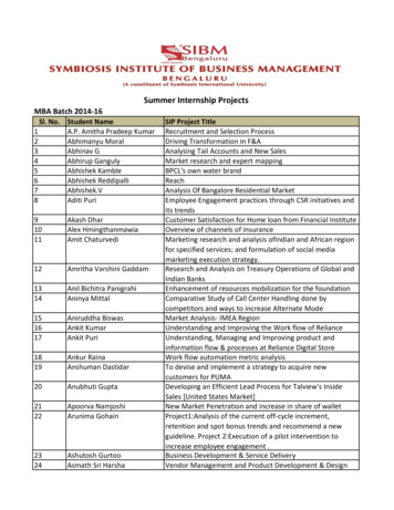
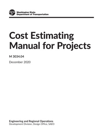
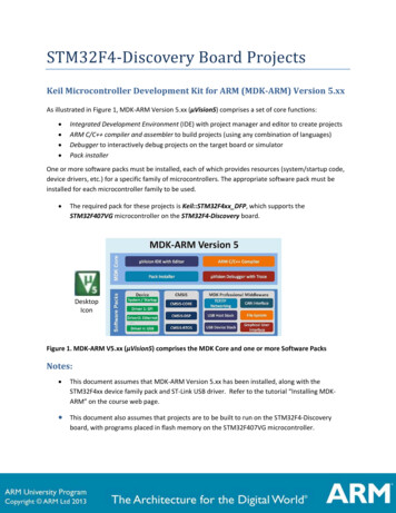
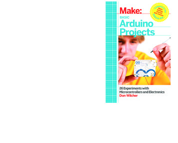
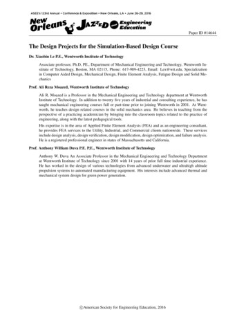
The stiffness of a bolted joint is another ideal topic for a minor project. Bolted joints are one ofthe most common elements in construction and machine design. Fasteners in the joints captureand join other parts by securing components with mating screw threads. The member stiffness ofthe bolted joints is a key design parameter for the successful bolted joint design. In thesimplified semi-empirical formula, the compressed volume of the member can be modeled as afrustum spreading from the bolt head or the nut to the midpoint of the grip as shown in Figure 1.Each frustum has a half-apex angle of α, which can be assumed to be 30 degrees [10]. Themember stiffness of the bolted joints can be solved via FEA simulation as shown in Figure 1.Through design thread course coordination, we discussed the details of the joint stiffnesscalculation and associated empirical formula in the course “design of machine elements”. Wedecided to use the analysis of the member stiffness of the bolted joints using FEA simulation asthe minor project for the modified MECH625.The main objectives of the minor project were: (1) integrate skills of FEA pre-processing andmesh refinement; (2) conduct simulation convergence analysis and (3) refine post-processingskills through the comparison of FEA simulation results with values from the empirical formulafor the stiffness of members in a bolted joint.It was assumed that the members in the bolted joints were fabricated from the same material.Then the bolted-joint could be simplified as a block with a center-through hole as shown inFigure 2. Each student would run his or her study cases which are listed in Table 2.Figure1 the model of compressed frustum and one image of an FEA simulation on a bolted jointFigure 2 the simplified bolted joint model for FEA simulation
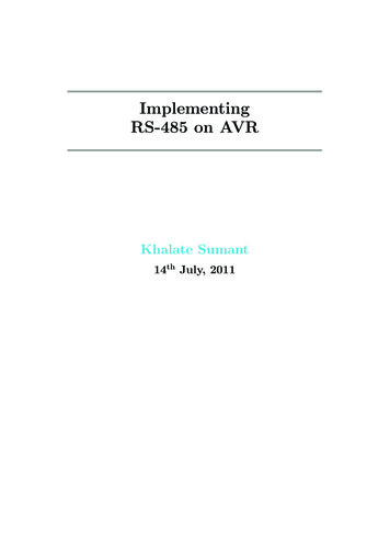
Table 2 the 21 different cases of FEA simulation on member stiffnessCase #1 78 1415 21Bolt size¼”, 5/16”, 3/8”, 7/8”, 1”,1 1/8”, 1 ¼”¼”, 5/16”, 3/8”, 7/8”, 1”,1 1/8”, 1 ¼”¼”, 5/16”, 3/8”, 7/8”, 1”,1 1/8”, 1 ¼”Material of membersSteel (AISI 1020)Aluminum (6061-T6)CopperDiameter-grip length ratio d/Ld/L 0.05, 0.075, 0.1, 0.25, 0.375, 0.5, 0.75, 1.0,1.25, 1.5, 1.75,2.0, 2.5d/L 0.05, 0.075, 0.1, 0.25, 0.375, 0.5, 0.75, 1.0,1.25, 1.5, 1.75,2.0, 2.5d/L 0.05, 0.075, 0.1, 0.25, 0.375, 0.5, 0.75, 1.0,1.25, 1.5, 1.75,2.0, 2.5The main activities of the minor project included: (1) create SolidWorks 3D models withinserting appropriate split lines; (2) conduct FEA simulation with convergence analysis; (3) usethe deflection from FEA simulation to calculate the member stiffness. Notes: students needed tochoose appropriate deflection for calculating the member stiffness. The type of deflections couldbe resultant defection or axial deflection. The values of the deflection could be the averagevalues of the clamping surface or on the inner circle, or on the middle circle; (3) compare themember stiffness from the FEA simulation with that from the empirical formula; (4) use theMicrosoft Excel to obtain an exponential curve-fit equation based on the FEA simulation results;and (5) write a technical report.Through this minor project, students harnessed their FEA simulation skills and also greatlyincreased their interests on FEA simulation. Students submitted technical reports uponsuccessfully completing the minor project.Major project: strength analysis of an engine hoistAt the end of week# 9, the major design project was released after we completed the use of FEAsimulation on assemblies. The key topics for assembly analysis included analyzing contactbetween components, simplified mathematical representations of connectors such as bolts, pinsand interference fits. Many of these topics were implemented in the major project.Creation of an appropriate design project for an undergraduate FEA simulation course was adifficult task. The following three main factors were considered during the development. First,the design project should have simple design functions and without dynamic loading. It wasconsidered critical that students could easily understand the operation or performance of themain components and sub-assemblies relative to the design constraints. For a project with asmall motion speed, static analysis was only required. Second, the design project should bemeaningful or a real product with design flaws purposely included. A real product could greatlyincrease students’ interests in conducting FEA simulation and redesigning it because the productwould require real design constraints / specifications. The experience they gained through thisproject could be an industrial hands-on real FEA simulation experience. Third, the designproject should be manageable because it was still a course design project. After carefulconsideration and collaboration among faculty, strength analysis of an engine hoist was chosenas the major project for the modified MECH625.An engine hoist or engine crane in Figure 3 is a common repair tool used in vehicle repair shopsto remove or install engines in the small and crowded vehicle engine compartments. It is alsoused in small workshops or homes to lift and move heavy objects. Engine hoists can be found in
both hardware and automotive parts stores. Some students even indicated they operated orowned such a product. The design specifications for the engine hoist in the major projectincluded a minimum factor of safety of 1.5 and maximum allowable deflection 0.375” at the endof the boom. Since the provide
curriculum. The design thread in our program includes courses in engineering design, engineering graphics, engineering statics, mechanics of materials, design of machine elements, material science, mechanical vibration, simulation-based design and senior design project. The MECH625 is a bridge course betwe