Transcription
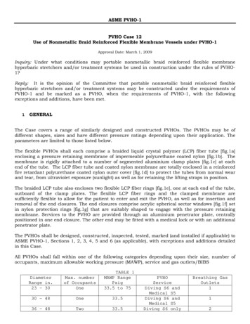
ASME PVHO-1PVHO Case 12Use of Nonmetallic Braid Reinforced Flexible Membrane Vessels under PVHO-1Approval Date: March 1, 2009Inquiry: Under what conditions may portable nonmetallic braid reinforced flexible membranehyperbaric stretchers and/or treatment systems be used in construction under the rules of PVHO1?Reply: It is the opinion of the Committee that portable nonmetallic braid reinforced flexiblehyperbaric stretchers and/or treatment systems may be constructed under the requirements ofPVHO-1 and be marked as a PVHO, when the requirements of PVHO-1, with the followingexceptions and additions, have been met.1GENERALThe Case covers a range of similarly designed and constructed PVHOs. The PVHOs may be ofdifferent shapes, sizes and have different pressure ratings depending upon their application. Theparameters are limited to those listed below.The flexible PVHOs shall each comprise a braided liquid crystal polymer (LCP) fiber tube [fig.1a]enclosing a pressure retaining membrane of impermeable polyurethane coated nylon [fig.1b]. Themembrane is rigidly attached to a number of segmented aluminium clamp plates [fig.1c] at eachend of the tube. The LCP fiber tube and coated nylon membrane are totally enclosed in a reinforcedfire retardant polyurethane coated nylon outer cover [fig.1d] to protect the tubes from normal wearand tear, from ultraviolet exposure (sunlight) as well as for retaining the lifting straps in position.The braided LCP tube also encloses two flexible LCP fiber rings [fig.1e], one at each end of the tube,outboard of the clamp plates. The flexible LCP fiber rings and the clamped membrane aresufficiently flexible to allow for the patient to enter and exit the PVHO, as well as for insertion andremoval of the end closures. The end closures comprise acrylic spherical sector windows [fig.1f] setin nylon protection rings [fig.1g] that are suitably shaped to engage with the pressure retainingmembrane. Services to the PVHO are provided through an aluminium penetrator plate, centrallypositioned in one end closure. The other end may be fitted with a medical lock or with an additionalpenetrator plate.The PVHOs shall be designed, constructed, inspected, tested, marked (and installed if applicable) toASME PVHO-1, Sections 1, 2, 3, 4, 5 and 6 (as applicable), with exceptions and additions detailedin this Case.All PVHOs shall fall within one of the following categories depending upon their size, number ofoccupants, maximum allowable working pressure (MAWP), service and gas outlets/BIBSTABLE 1MAWP RangePsig33.5 to 75DiameterRange in.23 – 30Max. numberof OccupantsOne30 - 48One33.536 - 48Two33.5PVHOServiceDiving S6 andMedical S5Diving S6 andMedical S5Diving S6 onlyBreathing GasOutlets112
The following design and performance criteria shall also apply:(a) The maximum allowable working pressure (MAWP) shall not exceed 75 psig. (0.52 MPa).(b) The outside diameters of the PVHOs shall be between 23in. (58.5cm) and 48in. (122cm) .(c) The maximum length shall not exceed 120 in. (305 cm).(d) The vessel shall have removable end closures, incorporating windows.(e) The design number of pressure cycles shall not exceed 4000 cycles.(f) The life of the flexible tube and end closure assemblies shall be 10 years from the date ofmanufacture or on completion of the allowable number of pressure cycles stated in Section 6Marking, whichever is achieved first.(g) The design operating temperature range shall be from 0 F to 100 F (-18 C to 38 C).(h) The design storage temperature shall range from -10 F to 150 F (-23 C to 66 C) using thestorage cases supplied with the PVHO.(i) The pressurizing gas shall only be air and a label to this effect shall be suitably displayed.(j) The breathing gases, oxygen or air, shall be supplied to the occupant(s) of PVHOs throughBIB masks or hoods. The operator shall select the breathing gas supply from the externalcontrol box. The operator shall also ensure that sufficient gases are available for flushing thePVHO if necessary, and have sufficient emergency gas supplies to complete the proposedtreatment safely. All exhaled gases shall leave the PVHO via an overboard dump(k) All PVHOs shall have fire protection as specified in the relevant section of PVHO-1 (5 and6)(l) All two (2) occupant PVHOs shall carry a hyperbaric fire extinguisherA User’s Design Specification shall be developed or provided for each model.2MATERIALSMaterials shall meet PVHO-1, para.1-6 PVHO Materials, with the exception of the flexible tubethat shall conform to Table 2 below. All of the materials of the flexible tube shall be used incombination to meet the performance requirements of this Case. A process control procedure inaccordance with 5.7 shall identify how the materials are to be used and in what specificquantities.All materials used in the manufacture of the flexible tube shall be supplied with supportingdocumentation consistent with the requirements of the Quality Management System detailed inSection 5 of this Case. Each lot used in the manufacture of the flexible tube shall meet thoseproperties listed.Material shelf life shall be identified as being suitable for long term storage between uses andshall not exhibit visual or performance deterioration through aging, for the entire life of thePVHO. The PVHO shall be stored in cases that meet the sealing requirements of IP67 andDEFSTAN 81/41.3DESIGN AND MANUFACTURE3.1 DesignThe PVHO shall be designed in accordance with ASME PVHO-1, and this Case.3.2 RequirementsIn section 1-7, Design and Fabrication Requirements of PVHO-1, the design and manufacture ofthe PVHO shall only be in accordance with paras. 1.7.4 to 1.7.11 and the followingrequirements.
(a) A detailed stress analysis shall be performed by a professional engineer registered in one ormore U.S. states, or the provinces of Canada, or licensed by any other country that hasequivalent licensing procedures and who is experienced in composite pressure vessel designand construction.(b) The stress analysis shall include full geometric modeling and a detailed finite elementanalysis of the PVHO and the flexible tube-to-window interface during assembly,disassembly, and under varying pressures up to a minimum of six times the maximumallowable working pressure (MAWP). The loads applied by lifting handles, straps and slings,as well as the position and weight of the occupants shall be considered.(c) The design analysis shall consider the effects of aging of the tube materials plus the effectsof folding, unfolding, and long-term storage of its components. The design shall ensure thatno damage will occur to any of the tube components by acute bending or by bending at lessthan the minimum bend radius for each component. Acute bending is defined as a bend inthe LCP braid or the flexible membrane at an inside angle of less that 5 degrees. Theminimum bend radius for the fiber or flexible membrane shall be no less that 0.05 in(1.25mm).(d) There shall be no penetrations in the pressure retaining section of the flexible tube of thePVHO.(e) The design and manufacturing process shall produce a flexible tube such that the assemblywill not be damaged by the assembly, pressurization, disassembly, or storage of the PVHO.(f) The maximum allowable working pressure (MAWP) shall be the lesser of 75psig or one sixth(1/6th) of the proof pressure test results.(g) The windows shall meet the requirements of PVHO-1, Section 2, Viewports, with theexception of para. 2-2.9, Viewport flanges. The design of the viewport flange shall beconducted as a part of the stress analysis requirement of para. 3.2(b) of this Case. Thewindows shall have standard window geometry (spherical sector with square edge) andqualify to meet the in-service guidelines of ASME PVHO-2.(h) The windows shall be fitted with a nylon protection ring secured to the windows with aretainer rigidly attached to the protection ring and sealed with an O-ring. The protection ringshall seal against the flexible membrane of the tube.(i) In lieu of the requirements of para. 4-9.6.1 of PVHO-1, the number of occupants will bedefined by the number of breathing gas outlets supplied and as defined in themanufacturer’s specification.(j) In lieu of the requirement of para. 6-3.1 (b) in PVHO-1, the minimum internal circumferenceof the flexible entry to the PVHO shall be 56 in. (142 cm), when the maximum overalldiameter of the PVHO is less than 23.5 in. (600 mm).(k)(l)All load bearing lifting handles, straps and slings shall be designed to meet therequirements of EN1492-1:2000 and be labeled. The number of occupants shall be takeninto account.Any changes to the design, materials or manufacturing procedures of the non-metalliccomponents of the flexible tube shall be cause for prototype retesting.
3.3 Design CertificationConformance of the design of the PVHO to the requirements of PVHO-1 shall be established byone of the two following procedures:(a) A professional engineer registered in one or more U.S. states, or the provinces of Canada, orlicensed by any other country that has equivalent licensing procedures, and who isexperienced in composite pressure vessel design shall certify that the PVHO was designedeither by him or under his direct supervision, or that he has thoroughly reviewed a designprepared by others, and that to the best of his knowledge, the PVHO complies with PVHO-1and this Case.(b) The design of the PVHO shall be reviewed by an independent third party agency experiencedin both nonmetallic pressure vessel design and PVHO systems, and as such organizationshall provide a certificate that the PVHO complies with PVHO-1 and this Case.3.4 ManufactureThe tube shall be manufactured in accordance with a detailed process control plan.The process control plan shall clearly define the details of the manufacturing steps necessary tofabricate the flexible tube, and shall document the fabrication process. Any anomalies foundduring the manufacturing process shall be fully documented and may be corrected according tothe process control repair plan. Any production testing already completed, shall need to berepeated.The materials and manufacturing processes used for production units shall be identical to thoseused for the tested prototypes.4TESTINGAll prototype testing shall be witnessed by an independent third party certifying agencyexperienced in composite pressure vessel technology. In lieu of the testing requirements ofPVHO-1, the following requirements shall apply.4.1Prototype Testing(a) Pressure Proof TestHydrostatic proof tests shall be performed on a least three (3) completely assembled PVHOsof the same design, shape, and format at maximum operating temperature. Each PVHO shallbe pressurized to six times design pressure and held without failure for a period of 30minutes. Failure of the acrylic window assembly or the release of a window through theends of the flexible tube shall be cause for failure of the prototype design. Should higherpressures be achieved, then the MAWP of the PVHO may be calculated using the applicableStatistical Analysis Method defined in Paragraph D-7 of the Non-Mandatory Appendix D.Regardless of test results, the MAWP defined in Section 1 (a) shall not be exceeded. Theouter protective cover may be removed from the assembled PVHO for the pressure proof testsin order to visually record and identify the mode of failure.(b) Drop TestA drop test of at least one complete PVHO of each size on concrete shall be conductedwithout failure. The PVHO shall be fitted with end closures and loaded with 200 lb (90 kg) ofbagged sand per occupant, and then pressurized to the MAWP. The PVHO shall be inclinedat 45 and elevated to a height such that the minimum distance to the concrete impactsurface is 3 ft (92cm) and then dropped. No leakage, damage, or permanent distortion of thePVHO is permissible.
(c) Cyclic Hydrostatic TestA cyclic hydrostatic pressure test of each size of completely assembled PVHO shall beconducted for between 4,000 and 10,000 cycles. The test shall comprise pressurization from2 psig (or less - but sufficient to ensure that the end closures remain sealed), to the MAWPand back to 2 psi at maximum operating temperature.The duration of a cycle shall be determined by adding the times for the two tests describedin a) and b) hereunder.1) To establish the time for the pressure cycle, a hydrostatic test will be conducted on thePVHO to determine the time taken for pressurization from ambient pressure to MAWP,plus the time taken for any changes in volume, caused by stress settlement, to subside.2) To establish the time for the depressurization cycle, a hydrostatic test will be conductedon the PVHO to determine the time taken for depressurization from MAWP to ambientpressure plus the time taken for any changes in volume, caused by stress relaxation tosubside.To establish the maximum number of cycles satisfactorily completed on the unit under test,the pressure retention properties of the vessel shall be checked every 2000 cycles for leakageor any damage to any component of the pressure retaining parts of the PVHO. Shouldleakage occur during cyclic testing, or at a cyclic level, then the maximum number of cyclesachieved at the previous cyclic level shall be defined as [CT] and be used to determine thenumber of approved operational cycles [CA] for the PVHO using the following calculation:CA [CT/2] – 1000(d) Extended Duration (Creep Rupture) TestA fully assembled pressure retaining part of the PVHO shall be subjected to proof pressuretesting at a pressure of five times the MAWP of the PVHO at maximum operatingtemperature for a period of at least 300 hours duration.If at the completion of testing, the following criteria are met, the PVHO shall be considered tohave acceptable creep behavior.A straight line shall be plotted using semi log coordinates with pressure on the linear scale(Y) and time on the logarithmic scale (X). The beginning coordinate of the line shall be thepressure at 0.1 hour and the MAWP mult
ASME PVHO-1 PVHO Case 12 Use of Nonmetallic Braid Reinforced Flexible Membrane Vessels under PVHO-1 Approval Date: March 1, 2009 Inquiry: Under what conditions may portable nonmetallic braid reinforced flexible membrane hyperbaric stretchers and/or treatment systems be used in construction under the rules of PVHO-