Transcription
Technical product documentation using ISO GPS - ASME GD&T standardsFOREWORDDesigners create perfect and ideal geometries through drawings or by means ofComputer Aided Design systems, but unfortunately the real geometrical featuresof manufactured components are imperfect, in terms of form, size, orientation andlocation.Therefore, technicians, designers and engineers need a symbolic language thatallows them to define, in a complete, clear and unambiguous way, the admissiblevariations, with respect to the ideal geometries, in order to guarantee functionalityand assemblability, and to turn inspection into a scientifically controllable process.The Geometric Product Specification (GPS) and Geometrical Dimensioning and Tolerancing (GD&T) languages are the most powerful tools available to link the perfectgeometrical world of models and drawings to the imperfect world of manufacturedparts and assemblies.This book is intended for designers, process engineers and CMM operators, andit has the main purpose of presenting the ISO GPS rules and concepts. Moreover,the differences between ISO GPS and the American ASME Y14.5M standard areshown as a guide and reference for the drawing interpretation of the most commondimensioning and tolerancing notations.A complete SolidWorks MBD tutorial has been added to the appendix of this book:SOLIDWORKS Model Based Definition (MBD) is a drawingless manufacturing solution that is embedded inside a SOLIDWORKS user interface. It helps companiesdefine, organise and publish product and manufacturing information (PMI) in a 3Dformat that complies with international standards.The author, Professor Stefano Tornincasa, has carried out research activitiesfor over thirty years in the field of functional design and geometric tolerances.He was President of the ADM Improve Association (Innovative Methods inPROduct design and deVElopment) from 2011 to 2015 and has publishedmore than 180 national and international scientific papers.He is co-author of the best-selling book on Industrial Technical Drawing, whichis currently adopted in the design courses of most Italian universities (E. Chirone,S. Tornincasa, Industrial Engineering Design, Volumes I and II, ed. Il capitelloTorino).Professor Tornincasa has conducted training courses on GD&T in many of themain manufacturing companies in Italy, and it is from this activity that he hasderived his skill and experience in functional design.His other research topics have been focused on product development, cycleinnovation through digital models and virtual prototyping methodologies (PLM)http://webd.polito.it/workbook/3
INDEXFOREWORD. PAGE 31. INTRODUCTION. 42. C LASSIFICATION AND INDICATION OF GEOMETRIC TOLERANCES. 93. D IMENSIONING WITH GEOMETRICAL TOLERANCES. 184. THE GD&T LANGUAGE ACCORDING TO THE ISO AND ASME STANDARDS. 22The fundamental ISO 8015 standard.25General geometrical tolerances.29The main differences between the ISO GPS and ASME GD&T standards.355. I NTERDEPENDENCE BETWEEN THE SIZE AND FORM. 37Maximum material condition.37Least material conditions.40Virtual condition.406. DATUMS. 42Indication of the datum features.44Location of a workpiece in a datum reference frame .48Selection of the datum features.49Types of datums.52Datum features referenced at MMR and LMR (Size datum) .55Customised datum reference frame.56Examples of other modifiers used to indicate datums.59Datum targets.61Contacting feature.657. FORM TOLERANCES. 68Straightness 8. ORIENTATION TOLERANCES. 79Parallelism.79Perpendicularity.82Angularity.859. LOCATION TOLERANCES. 89Position tolerances.89Position tolerance applied to median surfaces.93Effects of Specifying the MMR Modifier. 105Concentricity. 107Symmetry. 10810. PROFILE TOLERANCES.11411. RUN-OUT TOLERANCES.120Circular run-out. 121Total run-out. 12212. G EOMETRICAL PRODUCT SPECIFICATION FOR NON-RIGID PARTS.1241. Introduction to SOLIDWORKS MBD.1282. The first step towards MBD: making a 3D model the master by leveragingon modelling dimensions with annotation views.1303. Using DimXpert for coordinate tolerancing.1374. 3D Views.1485. GD&T with DimXpert.1546. Preparing the model and reading manufacturing information.1617. Leveraging on PMI.168INDEX. 172
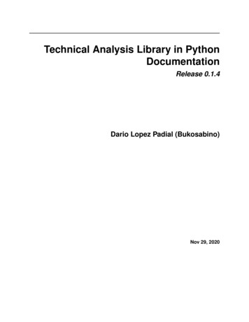
Technical product documentation using ISO GPS - ASME GD&T standards16,9dis minimtan umceFig. 52. Verification procedure of a shaft according tothe envelope principle or ASME Rule#1. The minimummaterial condition is controlled by an external gauge (themeasurement between two opposite points), while themaximum material condition is checked by means of anenvelope of perfect form with MMC dimensions.Envelope ofperfect formEnvelope ofperfect form(maximumcylinder)44,2 maximumtwo-pointdistances Fig. 53. Verification procedure of a hole according to the envelope principle. The minimum material condition iscontrolled by an internal gauge (measured between two opposite points), while the maximum material condition ischecked by means of a pin with the MMC dimensions.appropriate in the case of mating, may be restrictivefor all the other geometrical features, and maymake it necessary, in the latter case, to furnish anindication of exception (the ASME standards haveintroduced the È symbol, see Fig. 55), with theconsequence of a source of ambiguity being createdas it is not possible to be certain that the absenceof such an indication depends on the choic
Fixed fastener formula; 98 Flatness; 72 Flatness (ASME); 75 Floating fastener formula; 97 Form tolerances; 10; 68 Free State condition; 124 Functional dimensioning; 4 Functional gauge; 66. 111 Functional gauging techniques; 72 Functional limits; 28 Fundamental standard; 24. G. Gage; 33. 111 Gauges; 33 Gaussian (G) method; 59 Gaussian circle; 70File Size: 1MBPage Count: 8