Transcription
What’s New in theASME Y14.5 2009 Standard !2009-07-31Bill TandlerWith editorial contributions fromEvan Janeshewski and Ron GrubeMulti Metrics & SmartGD&T1. IntroductionIn March 2009 the ASME has released a new Y14.5 standard, the first since 1994, and there is much in it of greatinterest and benefit. In order to help potential users decide whether or not to adopt it, we attempt to cast some light onits most important novelties. To set the stage, we start with a definition of GD&T as a whole, in order to be sure we areall on the same page. Next we ask why a new standard might be interesting. Finally, we provide a brief overview ofthe contents of this evaluation before we go into detail.What is GD&T? GD&T is a symbolic language with which to research, refine and finally encode the functions of eachfeature of a machine part by specifying permissible limits of imperfection to guarantee its operation, assemblability,manufacturability and inspectability. Whereas CAD is dedicated to communicating the geometry of a part, GD&T isdedicated to communicating its functional requirements.Why do we need a “new” Standard? Standards always represent our best understanding of a topic at the time they arereleased. In most cases we keep learning as we go, and in the case of GD&T we have learned a lot since 1994. Themany changes contained in Y14.5 2009 represent very useful advances and clarifications which will further empowerthe designer to fully and reliably express the desired functions of machine parts. In particular, they will result insignificant benefits for Tolerance Stack-Up Analysis, for clear communication of manufacturing objectives, and forempowering coordinate metrology software. As we might suspect, however, not everything needing attention can beaddressed in a new standard, and there are a few disappointments which also need to be logged.Overview of the Most Important Changes: The most important changes in the 2009 Standard are presented in threegroups. Click on any topic to go there directly and then hit the “Return” button to come back, or simply scroll throughthe entire article. In order to fully comprehend much of this overview, it is imperative to have a copy of the 2009Standard at hand to study the figures referenced in the explanations, which limited space does not permit us to duplicatehere.2.New and refined Concept Definitions2a.2b.2c.2d.2e.2f.3.Material Condition ModifiersGeometric Tolerance Value Modifier DetailsMaterial Boundary Modifier DetailsDatum Feature SimulatorsDatumsActual Mating EnvelopesNew and refined Tools3a. Datum (Feature Simulator) Translation Modifier: 3b. Degrees of Constraint Modifiers: [u,v,w,x,y,z]3c. Explicit Datum Feature Simulator Size and Location Modifiers: [BSC] / [Ø15]1Copyright by Multi Metrics, Inc. Menlo Park, CA 2009 - All Rights Reserved
SmartGD&T Analysis of the ASME Y14,5 2009 Standard3d.3e.3f.3g.3h.3i.3j.3k.3l.4.Movable Datum Target (Simulator) SymbolComposite Feature Control Frames - Increased numbers of TiersDatum Reference Frame Axis Identifiers: X[A,B,C], Y[A,B,C] and Z[A,B,C]Unequally Disposed Profile Modifier: (U)Non-Uniform Modifier: [NON-UNIFORM]ALL OVER Modifier: (())Continuous Feature Modifier: CF Independency Modifier: (I)The “True” Modifier: TRUEDisappointments4a.4b.4c.4d.4e.4f.Loss of the RFS and RMB Modifier Symbols (S)Failure to Clean up or Eliminate the Concentricity & Symmetry ToolsFailure to Clean up the Radius ToolsFailure to Clarify the “Datum Feature Shift” ConceptA Still only Partially Adequate Topic Index.Incomplete Explanation of the Functional Objectives of the “Geometric Tolerance Value” [ToleranceZone Size] Modifier (L)4g. Need to Eliminate the Term “Resultant Condition” and Refine the term “Virtual Condition”4h. Inadequately Precise Definition of a Basic Dimension4i. Need to Discontinue use of the Word “True”2. New and Refined Nomenclature, Definitions & Effects2a. Material Condition Modifiers - (S), (M) and (L)What: Clarification of Concepts and Separation of the Modifiers into two Groups: “Geometric ToleranceValue” and “Material Boundary” Modifiers”, plus Elimination of the explicit Modifier (S).Where: §2.8 pp.29 and §4.11.3 – 4.11.8 pp.59-63.Objective: To clearly differentiate between the effects and use of these modifiers when applied to tolerancevalues versus datum features.Ratings: Usefulness [high]In order to significantly clarify their different effects, the 2009 Standard separates the material conditionmodifiers (S) [no longer defined], (M) and (L) into the two functional groups defined below: 1) “GeometricTolerance Value” modifiers when associated with tolerance values, and 2) “Material Boundary” modifierswhen associated with Datum Features.Unfortunately, the 2009 Standard forbids explicit use of the symbol (S). For details, see Section 4.a).“Geometric Tolerance Value” Modifiers: These modifiers are associated with the tolerance value in a featurecontrol frame, and fix or permit an increase in the size of a tolerance zone. They are decoded as follows whenreading a Feature Control Frame: RFS “Regardless of Feature Size” – the default modifier [no symbol]MMC “at Maximum Material Condition” – symbol (M)LMC “at Least Material condition” – symbol (L)See Section 2.b of this document for clarification of their functional impact.2Copyright by Multi Metrics, Inc. Menlo Park CA 2009 - All Rights Reserved
SmartGD&T Analysis of the ASME Y14,5 2009 Standard“Material Boundary” Modifiers: These modifiers are associated with the Datum Features referenced in afeature control frame, and determine the stabilizing or mobilizing impact of Datum Feature Simulators duringthe Datum Reference Frame establishment process. They are decoded as follows when reading a FeatureControl Frame: RMB “simulated Regardless of the Material Boundary” – the default modifier [no symbol]MMB “simulated at the Virtual Maximum Material Boundary” – symbol (M)LMB “simulated at the Virtual Least Material Boundary” – symbol (L)See Section 2.c of this document for clarification of their functional impact.DETAILSAlthough the 2009 nomenclature changes for the individual modifiers provide substantial improvement byfinally differentiating between their names in accordance with their different applicability, a last recommendedstep would be to rename their groups as follows, to provide a thoroughly visceral connection with theirfunctions:1) Current: “Geometric Tolerance Value” modifiers.Recommended: “Tolerance Zone Size” modifiers.2) Current: “Material Boundary” modifiers.Recommended: “Tolerance Zone Mobility” modifiers.The intrinsic purpose of Feature Control Frames is to define the shape and size of tolerance zones, and thecoordinate systems relative to which they are to be oriented and located.The impact of the newly named “Geometric Tolerance Value” modifiers is to specify whether a tolerance zoneis to be fixed in size in the presence of the RFS modifier, or be free to expand in the presence of an MMC orLMC modifier. They are in fact “Tolerance Zone Size” modifiers. Why not call them that?The impact of the newly named “Material Boundary” modifiers is to determine the permissible “mobility” of aDatum Reference Frame relative to a particular Datum Feature by specifying the behavior of its simulator.Whereas the RMB modifier “stabilizes” the Datum Reference Frame relative to the specified Datum Feature,the MMB modifier (M) “mobilizes” the frame, and the LMB modifier (L) “loosens” the frame relative to thespecified Datum Feature. Since tolerance zones are attached to Datum Reference Frames by Basic dimensions,the impact of the “Material Boundary” modifiers is to either stabilize or mobilize the tolerance zones as well asthe Datum Reference Frame relative to the Datum Features of the part, and therefore to encode whether mutualplay between mating parts may or may not be taken advantage of during assembly. As a result, they are in fact“Tolerance Zone Mobility” modifiers. Why not call them that?2b. “Geometric Tolerance Value” Modifier DetailsWhat: Clarification of the Method for Calculating “Bonus” Tolerance Values.Where: §2.8.1 through §2.8.5 pp.29-31.Objective: To clarify the process for determining of the effective size of a tolerance zone under the influenceof the “Geometric Tolerance Value” modifiers (M) and (L).Ratings: Usefulness [high]3Copyright by Multi Metrics, Inc. Menlo Park CA 2009 - All Rights Reserved
SmartGD&T Analysis of the ASME Y14,5 2009 StandardThe methods for determining the effective size of a tolerance zone under the impact of an (M) or (L) modifierare clarified in the indicated paragraphs.DETAILSIn particular, in the presence of the modifier (M), the specified tolerance increases by the absolute value of thedifference between the MMC size of the feature and its unconstrained, in-space actual mating size, and in thepresence of the modifier (L), the specified tolerance increases by the absolute value of the difference betweenthe LMC size of the feature and its unconstrained, in-material actual mating size.2c. “Material Boundary” Modifier DetailsWhat: Expanded Applicability and Impact Clarification.Where: §4.11.3 p.59 through §4.16 p.74. Figs. 4-29 through 4-32 pp.71-74Objective: Refinement of Datum Reference Frame Establishment processes in the case of planar and nonenveloping Datum Features.Ratings: usefulness [high]In addition to common features of size, the 2009 Standard makes the RMB [no symbol], MMB (M) and LMB(L) “Material Boundary” modifiers applicable to location constrained, planar and non-enveloping, rotationconstraining Datum Features, and thereby closes a significant “black hole” in all previous versions of theStandard. It does so by allowing the designer to use these modifiers to clearly differentiate between alternativefunctional objectives in ways not possible before. For details, see Y14.5 2009 Figures 4-29 through 4-32 onpp.71-74.2d. Datum Feature SimulatorsWhat: Concept Update (True Geometric Counterpart).Where: §1.3.17 p.3 §4.5 & 4.6 p.53 §4.11 through 4.17 pp.59-75.Objective: To clarify the Datum Reference Frame establishment process.Ratings: usefulness [high]For purposes of defining the Datum Reference Frame establishment process, the 2009 Standard substitutes theconcept of the Datum Feature Simulator – “a theoretically perfect, or physically almost perfect, inverse DatumFeature” – for the “True Geometric Counterpart” concept, allowing for a much more visceral understanding ofthe Datum Reference Frame establishment process.DETAILSIn particular, a Datum Feature Simulator, whether theoretically perfect, or physically “almost” perfect, is nowclearly understood as the entity: from which we extract Datums,in which we first establish Datum Reference Frames, and4Copyright by Multi Metrics, Inc. Menlo Park CA 2009 - All Rights Reserved
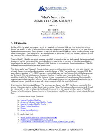
SmartGD&T Analysis of the ASME Y14,5 2009 Standard with which we transfer Datum Reference Frames to actual parts by marrying their DatumFeatures to their simulators.These concepts together with the new “Material Boundary” modifier terminology, significantly improve thecomprehensibility of the Datum extraction and Datum Reference Frame establishment processes.2e. DatumsWhat: Concept Clarification.Where: Fig. 4-3 p.50 and §4.11 pp. 59-65.Objectives: To improve users’ understanding of these concepts in order to ensure better implementation inDesign and better application in manufacturing and coordinate metrology.Ratings: usefulness [high]The 2009 Standard significantly clarifies the concept of Datums showing for the first time that Datums areextracted from Datum Feature Simulators - not from Datum Features - that a Datum can be one of the sixalternatives illustrated above, and exactly which Datum type a particular simulator defines. The new Standardfurther shows which degrees of freedom each Datum type constrains when acting as a primary Datum – seeFig. 4-3 p.50.DETAILSUnfortunately the new Standard fails to state the very simple general rule for extracting Datums from DatumFeature Simulators, namely: “Datums are the minimum integrated set of a single mathematical reference point,and/or axis, and/or plane which together fully characterize the orientation and location of a Datum FeatureSimulator.” Thus there are six possible Datums: 1) a single point, 2) a single line, 3) a single plane, 4) a pointon a line, 5) a line in a plane and 6) a point on a line in a plane. Although missing some important instances,these are clearly shown in Fig. 4-3 p. 50.2f. Actual Mating EnvelopesWhat: Concept Clarifications.Where: §1.3.25 and §1.3.26 pp. 4-5.Objectives: To improve users’ understanding of these concepts in order to clarify their impact onmanufacturing and coordinate metrology processes.Ratings: usefulness [high]The referenced paragraphs in the 2009 Standard clarify the concept of the “Actual Mating Envelope”, andmake valuable contributions to inspection and manufacturing process control in spite of some terminologydifficulties.In fact, the “Actual Mating Envelope” of an actual physical feature is the effective “in-space”, or “in-material”envelope which just includes or excludes all the points on its surface under three different conditions: 1)unconstrained, 2) orientation constrained, or 3) location constrained. The terminology difficulties stem fromthe use of only two terms “unrelated” and “related” to refer to the three listed conditions, and are increased bythe use of the term “minimum material”. The three in-space cases are illustrated in the figure below.5Copyright by Multi Metrics, Inc. Menlo Park CA 2009 - All Rights Reserved
SmartGD&T Analysis of the ASME Y14,5 2009 StandardUnconstrainedin-spaceActual M ating E nv elopeLocation Constrainedin-spaceActual M ating E nv elopeThe B asic Bore AxisOrientation Constrainedin-spaceActual M ating E nv elopeThe Actual Mating Envelope concept has two major applications: 1) It is the basis for calculating a tolerancezone size bonus in the presen
Datum Reference Frame Axis Identifiers: X[A,B,C], Y[A,B,C] and Z[A,B,C] 3g. Unequally Disposed Profile Modifier: (U) 3h. Non-Uniform Modifier: [NON-UNIFORM] 3i. ALL OVER Modifier: (()) 3j. Continuous Feature Modifier: CF 3k. Independency Modifier: (I) 3l. The “True” Modifier: TRUE 4. Disappointments 4a. Loss of the RFS and RMB Modifier Symbols (S) 4b. Failure to Clean up or Eliminate the .