Transcription
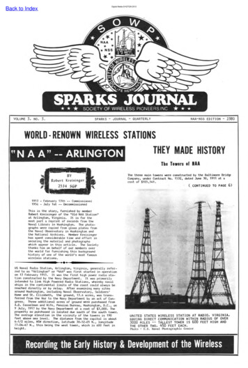
Digital Media K2TQN 2012Back to IndexVOLUME 3, No.3.SPARKS - JOURNAL - QUARTERLYNAA-NSS EDITION - 1980WORLD · RENOWN WIRELESS STATIONSTHEY MADE HISTORY N A A" -- ARLINGTONThe Towers of IIIThe t hree main towers were constructed by the Baltimore Brid Company, under Contract No . 1532, dated June 30, 1911 at acost of 105,541.( CONTINUED TO PAGE 6)1913 - February 13th -- Commissioned1956 - July 1st -- DecommissionedThis is the story , furnished by memberRobert Kreisinger of the "Old NAA Station"at Arlington, Virginia. It is for themost part a reprint of records from theNaval Library in Washington . The photographs were copied from glass plates fromthe Naval Observatory in Washington andthe National Archives . Member Kreisingerhas spent considerable time and effort insecuring the material and photographswhich appear in this article . The Societythanks him on behalf of our members overthe world for furnishing this backgroundhistory of one of the worJd's most famouswireless stations US Naval Radio Station, Arlington, Virginia, generally referred to as "Arlington" or "NAA" was first started in operationon 13 February 1913. It was the first high power radio sta tion constructed by the Navy Department. It was primarilyintended to link High Powered Radio Stations , whereby navalships in the continental limits of the coast could always bereached directly or by relay . After examining many sitesaround Washington , including Naval Observatory, Soldiers 'Home and St. Elizabeth, the ground, 13.4 acres , was transferred from the War to the Navy Department by an act of Congress . Three additional acres of ground were purchased fromA. B. Casselman and Wife , Pensio Bureau, Washington, D.C., on9 July, 1917 by the Navy Department at a cost of 3,000. Theproperty so purchased is located due south of the south tower.The average elevation i n the vicinity of the towers is 190feet above sea level. The distance from the capital is about4-1/2 miles, WSW direction, latitude 38-52-05 N. , longitude77 - 04-47 W., this being the west tower, which is 600 feet inheight.UNITED STATES WIRELESS STATION AT RADIO, VIRGINIA,HAVING DIRECT COMMUNICATION WITHIN RADIUS OF OVER3000 MI LES -- TALLEST TOWER IS 600 FEET HIGH ANDTHE OTHER TWO, 450 FEET EACH.Photo - U.S. Naval Photographic CenterRecording the Early History & Development of the Wireless
Digital Media K2TQN 2012Back to IndexNAA - NSS EDITIONSPARKS JOURNALThe "Magic" Callof Early Day Wireless!ROBERT KREISINGERThe well house has an ordinary sloping roof of wood and tin.This house contains a motor driven well pump of a capacityof ten gallons per minute, which pumps water from a well 155feet deep to the water tank above mentioned . This well supplied sufficient water for the station until 1916, at whichtime the Bureau of Engineering was requested to plan ' to connect this station with the water supply at Fort Meyer Military Reservation. This connection was completed in the fallof 1916.I;lAUTHOR11I1THE ARLINGTON STORYThe 600-foot tower has an elevator shaft framing and two rungsteel ladder stairs with landing platforms at 15-foot intervals. It has a weather vane, three electric panel cabinetsand a conduit lamp post at the top with electric cable to theground. The 450-foot towers have steel stairs with landingplatforms at various intervals. The north legs of the northtower are at a level 20 feet lower than the other legs. The450 and 600 foot towers weigh about 275 and 442.5 tons respe tively.In 1922 two new towers were errected east of the station; oneabout two hundred feet east of the south tower and the otherabout eight hundred feet east of the north tower. They aresteel skeleton construction, self supporting, 190 and 200feet high respectively and were completed about September1922. These towers are 34 feet on a side at the base, onetapers to 2 feet at the top and the other with a similartaper, has had ten feet of the top removed. Each of thesetowers has a single rung steel ladder .During 1926, four (4) mast, forty (40) foot high were erectedon the roof of the wireless buildings to support the highfrequency antennas . These masts are of 4" galvanized steelpipe, set in concrete and supported by guide-wires insulatedevery ten feet.a. aroa. 1The grading, etc., for the foundation of the wireless buildings was done by R.J. Beall Construction Co ., Contract No .1864, dated June 28, 1912 at a cost of 5,420.20.The wireless buildings were constructed by Arthur Cowsill,Contract No. 1521, dated June 29, 1911 at a cost of 68,883.The wireless buildings consist of a transmitter building, areceiving building, and a small well house, the first two ofwhich are connected by a covered passageway.All buildings are built of tapestry brick and the main buildings are furnished off with cornices of buff terra co ta,which was later covered wIth sheet metal and painted buffcolor. The roofs of the buildings are of concrete and tiling with five layers of three ply tarred paper, topped witha thick coat of tarred slag for water proofing. These roofsare supported by very heavy "I" beams, and the roof of thetransmitter building is made stronger to support a cypresswater tank having a capacity of 10,000 gallons.nm. I!\ IF I!} 1 I!} IFaVM The Administration Building was constructed by W.E. Mooney,Specification No. 2141, dated July 30, 1915 at a cost of 16,966. This building is built of tapestry brick and furnished off with buff terra cotta cornices. It contained tenoffice rooms, a coal storage room, furnace room, two storagerooms for old correspondence and a garage. This buildingwas recently converted into quarters for the Officer inCharge, on the first floor and the second floor was convertedinto quarters for two Chief Petty Officers.lThese towers are of ornamental steel construction, one sixhundred and the other two four hundred and fifty feet high.The center of the larger tower is at the apex of an isosclestriangle and the centers of the small towers are at the endof the base of this triangle. The base is .350 feet long, theperpendicular from the center of the base to the apex is 350feet and the legs about 391 feet. The large tower has abase 150 feet square and each leg of which rests upon and isbolted to a concrete foundation. The small towers have abase 1: feet square with each leg supported as above . Theseconcrete foundations are about 6 feet square at the top andgradually increase in size until at the bottom, 14 feet fromthe top, they are 12 feet square and each foundation is sunkfrom 10 to 14 feet into the ground. Each leg of the towersis insulated by means of a large slab of marble and marblewashers thoroughly dried and varnished. This slab has beentested up to 150,000 volts. The holes in the marble throughwhich holding down bolts pass are filled with sulphur to further preserve the insulation. At the present time the towersare securely grounded. On top of each tower there are twooutriggers each 30 feet in length. There are hand winches ontop of each tower for use in handling antennas . Motor drivenantenna hoists are installed on the ground at the base ofeach tower. These were installed by the Ledgerwood Mfg. Co.Contract 1974, dated June 27, 1913 at a cost of 5,437 . 50.\'" '" I!!!S WPM l11(CONTINUED FROM FIRST PAGE)aui l i.'1(1(11111(The Septic Tanks were constructed under Contract No. 1521.The tanks have a concrete foundation, reinforced concreteside walls, and reinforced concrete roof. These tanks areconnected with all the buildings at this station.111{lThe reservation fence and gates were constructed by L.M.Johnson, Contract No. 1982, dated June 27, 1913, at a costof 2,206.41.(1 The reservation roads and walks, etc ., were constructed byB. M. Smith, Contract No. 2230, dated June 12, 1916, at acost of 1,129.50.{l(IOrigilal ' llltaliatiol11l The original install ation consisted of a 100 K.W. spark -8et1 constructed on the Fessenden system. The main driving unitwas a Westinghouse 200 H.P., 220 volt, ,25 cycle, 3 phase,Synchronous motor, 300 revolutions per minute. The 100 K.W.(General Electric Co.) 500 cycle, belt driven, 1250 revolu-(III1 III 1lI 1lI!1l1!lI . ;;;: .II ;BE THE 5 KW SPARK TRANSMITTER. 1 TOTHE NAVY STANDARD 2 KW TRANSMITTER THE OSC. TRANS. TO THE LOWER LEFT OF THE PRINT APPEARSIT IS SIMILAR TOUSED IN wW-l. THEWHEEL FOR CHANGING WAVE AND THE LEVER FOR ADJUSTINGTHE COUPLING CAN ALSO BE NOTED.vI!} 1* I!\ MVI!} 71\ 71\11\ 71\ OOls0s1l\lS\Ji"!!!S *11\11\ "V!!MiSM IS' Jl!l\ Jl!l\ leVI!} 00 00 ooa,," 00 00000000 III' 00If00II".
Digital Media K2TQN 2012Back to Index AAKS i \tions per minute, generator had the revolving portion of theSynchronous rotary gap. The condensers were of the compressed air type, the antenna consisted of three flat top sec tions stretched between the three large towers , 23 wi res toa section, individual wires were 7 strands of 0. 032" diameter(f20) phosphor bronze, preaders of each section bei ng 88feet long. The two west ends of flat tops were open at the600 foot tower, the sections between north and south towerswere connected by jumpers to the other flat tops, the leaddown to the transmitter was a f an shape down 300 feet, thenall wires were bunched for entering the buildi ng. Thisantenna appangement had a fundamental of 2100 meters (142. 9KCs) with a capacity of 0.0094 M.F. It was provided with aswitch to be used as a transmitting or receiving antenna . Thesecond set installed was a small 5 K.W. transmitter with antenna 300 feet high. This set was for communicating withPhiladelphia, New York, Norfolk and for local radio work. Thethird set was a 100 K.W. Federal Telephone Co. arc set . Thepower unit consisted of a General Electric Co., 500 volts,100 K.W. D.C., the two units direct connected.NAA - NSS EDITIOOThe records of words transmitted by the War Department fortwelve months ending December 1927 totaled 3,260,340 . Thisconsisted of official messages and weather information. 100%of all messages originating in the War Department was handledthrough the Arlington Station.Since January 1, 1925 the following inspections were held atthis station:One June 30, 1925 by Commander R.T.S. Lowell, U. S. N., whograded operations, personnel and material as excellent andmade following remarks as a summary of work accomplished intwo months previous to inspection:"(a) Installed a 1-1/2 K.W. C.W. tube transmitted forthe Army replacing the 500 watt A.C. tube transmitter previously handling this traffic.(b) Conversion of the 6 K.W. C.W. tube transmitter to10 K.W. output on same wavelength.(c) Installation of 500 watt broadcast transmitter.(d) Installation of 20 K.W. C.W. master oscillatorcoupled circuit tube transmitter - 95% complete,and now undergoing test.All installation but the 20 K.W. was performed by the stationforce. In addition, the station force has also constructed anew 350 foot antenna for the 1-1/2 K.W. transmitter and a 70foot antenna for the broadcast set. The station force further removed the General Electric 500 watt TO transmitter andthe old broadcast set.· All of the work performed has been ofthe highest order and has been done absolutely without anyinterruption of traffic."One December 13, 1925 by Lieutenant W. Klaus, U.S.N., whograded operations, personnel and material excellent and madefollowing remarks:"When the 20 K.W. tube transmitter was completed it was foundthat the existing main antenna was too small to take the fulloutput of the set . The station force, assisted by the NavyYard, remodeled the antenna by the addition of wires in the1 top and replacing the rat tail with a cage lead in. This permi tted operation of the set at around 25 K. W. output. \ henthe set was pushed to full output corona occurred at the free; endof the antenna attached to the west tower .! THE FAMOUS "VOICE OF ARLINGTON" THE 100 KWTRANSMIITER. REMOVED FROM - S VIC'E IN 1925.lf1lDuring 1924 and 1925 the 100 K.W. spark and arc sets, alsothe 5 K.W. spark set, were removed from the station and fivevacuum tube transmitters were installed by Navy personnel.During 1926 four (4) High Frequency 10 K.W. sets were underconstruction at U.S. Naval Research Laboratory, Bellevue,D.C., for this station. The first set was delivered earlyin the year 1927. Much experimental work was done duringthe year and the last set was delivered and installed December 1, 1927. One 250 watt High Frequency set was installedat this station on April 15, 1927. The present installationconsists of one 20, one 10, one 1-1/2 and one 1 K.W. vacuumtube transmitters, also four 10 K.W. and one 250 watt HighFrequency transmitters.II1. M "a'U the t1'8nsml-tters is exeellent. Amountof stores and replacement parts on hand not cons idered s uffi cient but are limited by the i nsufficient maintenance allowance of a station with the number and power of first-classtransmitters such as at Arlington.The .eonMUThe cleanliness and preservation of the station and materialas a whole are excellent."Picture CreditlThe pictures used in this article are official U.S. Navypicture 1furnished by courtesy of the U. S. Naval Observatory and made frorltheir original glass plates. Thanks to Member Kreisinger forhis time and effort taken to obtain these early-day pictures forthe Society's use. They present a truely remarkable glimpse intothe past and our early heritage.The 1000 watt broadcast radio telephone formerly atthis station was removed during December 1926 andinstalled at the Navy Yard, Washington, D.C.During the twelve months ending June 30, 1915arlington handled 78,921 messages. This station habeen used for important experimental work along withthe development of the Radio Art, including longdistance radio telephone tests in 1915 and laterelectron vacuum tube transmitters.IFIA study of traffic nandled by the Navy Departmentfor a month in the early part of 1926 shows thatthe 20 and 10 K.W. transmitters alon cleared367,000 words and as an equal amo
steel ladder stairs with landing platforms at 15-foot inter . B.M. Smith, Contract No. 2230, dated June 12, 1916, at a cost of 1,129.50. Origilal 'llltaliatiol The original installation consisted of a 100 K.W. spark-8et constructed on the Fessenden system. The main driving unit was a Westinghouse 200 H.P., 220 volt, ,25 cycle, 3 phase, Synchronous motor, 300 revolutions per minute. The .