Transcription
INSTALLATION, OPERATION&MAINTENANCE MANUAL.BERG BT-96XX COOLING TOWERSBERG
Model:BT-96XX-XXSerial Number: W02984A-DD1-0715For 24 hour service inquiries, please call(416) 755-2226
BERG COOLING TOWERSOPERATION & MAINTENANCE ductionUncrating and Damage AssessmentCooling Tower LocationCooling Tower InstallationSystem Start-UpSystem with Remote Indoor Tank OperationWinter OperationCooling Tower InternalsMaintenanceAir Conditioning Connections (Option)Basin Heater (Option)Troubleshooting.
WARRANTYBerg Chilling Systems Inc. (“Berg”) warrants that the Products it manufactures shall conform tothe specifications as provided in the quotation and will be free from defects in workmanshipand material when used under conditions we recommend. Berg’s obligation under thiswarranty is to the original purchaser only and is limited to repair or replace or otherwise makegood, any part of equipment of our manufacture, which within one year after the date ofshipment to a destination within Canada or continental United States of America (“theTerritory”), and upon our examination, shall disclose to our satisfaction to have been defective.(If the equipment is located outside “the Territory”, a parts warranty only, ex works our factory,shall apply for one year from the date of shipping per paragraph 6 of our Standard Terms andConditions of Sale.) Berg neither assures, nor authorizes any other persons to assume for us,any liability in connection with the sale of our equipment except under the conditions of thiswarranty. This is an implied warranty of merchantability and or fitness for a particular purpose;all other implied warranties and any liabilities not based upon contract are hereby disclaimedand excluded by this warranty.The warranty does not cover any field (on site) labour charges during overtime hours (5:00pmto 8:00am or during weekends and holidays) nor dies it cover charges, labour or otherwise,associated with travel and accommodation, adjustments and maintenance, or work doneoutside of Canada and continental USA. Any cost differential for overtime labour charges willbe the responsibility of the Buyer.This warranty is voided and shall not apply to any apparatus, which in our opinion, has beensubject to misuse, negligence, or pressures in excess of limits recommended by Berg, orwhich have been repaired or altered outside Berg’s factory or which have the serial number(s)removed or defaced. This warranty does not cover refrigerant gas or any labour associatedwith its evacuation or replacement nor does it cover any apparatus damaged from freezing ofwater or heat transfer fluid.Replacement of defective material will be ex works our factory. Berg is not responsible for anysales, use, excise, duty or any other applicable taxes associated with the replacement of partsor labour under this warranty. This warranty is only effective with all the terms and conditionsof this quote being met, and it is understood that time is of the essence in this agreement. ThisWarranty is not transferable.In accordance with paragraph 7 of our Standard Terms and Conditions of Sale, under nocircumstances shall Berg Chilling Systems Inc. be liable for loss of prospective or speculativeprofits, or special, indirect, incidental, or consequential damages.All warranty service must be authorised by Berg prior to any work being performed and have aBerg Purchase Order issued. All defective parts become the property of Berg and must bereturned, transportation prepaid, as advised by Berg. Warranty Claim Forms, found in theowner’s manual, must accompany all warranty claims or parts returns or this warranty shall notapply.
The replacement of component parts not of our manufacture will be limited to the warranty ofthe manufacturers of such parts. Berg shall transfer to the Buyer whatever transferablewarranties and indemnities Berg receives from the manufacturers of any sub-components ofthe Products, if any, including any transferable warranties. This warranty is a part of theStandard Terms and Conditions of Sale of Berg Chilling Systems Inc.
1.0.0INTRODUCTIONYour BERG CHILLING SYSTEMS INC. COOLING TOWER has been engineered and carefullyassembled using only the highest quality raw materials and components to provide trouble-freeservice with a minimum of maintenance. It is covered by a limited 5 Year Warranty* on all partsand labor.WARNING.Adjustment of any internal components, fan blades,external controls, or valves by unqualified personnel is done at the severe risk ofpermanent damage to the cooling tower unit. Improper adjustments may result ina loss of efficiency and/or capacity, and, most importantly, the warrantyagreement becomes null and void.It is highly recommended that this manual be carefully reviewed by the proper personnel priorto the installation or operation of the cooling tower.
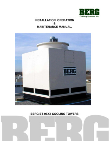
2.0.0Uncrating and Damage AssessmentRemove the packaging material and examine the cooling tower for any signs of shippingdamage. It is advisable to pay particular attention to the basin, making sure that there are nosigns of cracks or any other penetrating damage.The consignee is responsible for making claims to the transportation agent.Any and all damage should be reported to the local Berg representative upon discovery.WARNING.Lifting of the Cooling Tower should only carried out bytrained personnel using an overhead crane. When lifting, four chains must beproperly connected to the four lifting Lugs provided on the steel base. These chainsmust be separated using ‘Spreader Bars’ to avoid damaging the tower during liftingand installation.
3.0.0Cooling Tower LocationThe cooling tower must be located outdoors. The most convenient location is usually up on theroof. In cases where the rooftop location is not an acceptable option, BERG can provide prefabricated cooling tower stands ready for on-site field erection. These tower stands mayrequire a special reinforced concrete footing so please contact your local Berg representativefor additional information.To prevent potential blockage through the air intake louvers, the cooling tower should be kepta minimum of 6 ft away from any obstruction.
To prevent re-circulation, the cooling tower should be kept a minimum of 6 ft away from anywall or other cooling tower and there should be no obstruction or roof present over the airdischarge as this too results in re-circulation.In cases where a remote indoor tank is to be used, the cooling tower must be elevated to aheight above the indoor tank level. This allows the cooling tower to drain through the return lineby gravity to the indoor tank.Locating the cooling tower in an accessible area is recommended as it makes maintenanceand inspections more permissive in addition to making the installation easier.
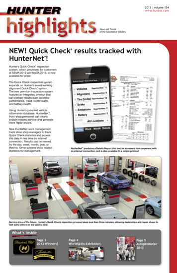
4.0.0Cooling Tower Installation : Standard Hoist Signals.
Use the 1" white gasket included to line the region around the top of the cooling tower. Makesure that none of the holes are covered by the gasket.The fan motor assembly is shipped separately from the rest of the cooling tower. The requiredbolts and washers are included with the fan motor assembly and these are to be used forinstallation. Please read the FAN MOTOR INSTALLATION AND MAINTENANCEINSTRUCTIONS at the end of this manual before installing the fan motor.
Only use the fasteners supplied with the unit.Using the fasteners supplied, secure the fan motor assembly to the rest of the cooling towerbefore locating the cooling tower onto a rooftop or support structure. Align the stickers with theletters A, B, and C prior to fastening to ensure that mounting points are lined up.Do not use excessive torque on the fasteners.It is highly recommended that the joint area between the cooling tower and the fan motorassembly be filled with silicone.The cooling tower is to be lifted using the lifting lugs present in each top corner. When lifting,use these lifting lugs only.1Each lifting lug is rated for a maximum vertical load of 2,400 lb.2Check that the basin is empty of water before lifting the cooling tower.A substantial foundation is required to support the operating weight (cooling tower dry weightof cooling tower and weight of the water) of the cooling tower.It is highly recommended that an experienced contractor be enlisted toprovide an adequate supporting structure.Berg Chilling Systems Inc. accepts no responsibility for the feasibility of mounting thecooling tower onto the roof.It is the customers responsibility to ensure that the roof is sufficiently reinforced to handle theaddition of the aforementioned operating weight.It is recommended that the cooling tower be placed onto sleepers. 6" x 6" pieces of pressuretreated lumber or equivalent is recommended.Ensure that line voltage agrees with electrical nameplate. Line voltage should be within 10 %limitations. The electrical power should be supplied through a fused disconnect and inaccordance with local electrical codes.
Use a pipe hanger to support the first fitting from the cooling tower (See diagram above). Thiswill assist in minimizing vibration and reduce the stress on the FPT connection from the coolingtower inlet.In order to maximize the cooling tower efficiency, the unit must be in a level position. Thisensures equal water distribution through the fill/wet deck and optimum basin capacity.At the connection point between the sump base and the flange it is recommended thatneoprene gaskets (provided by others unless specified) be used when mounting bolts arebeing permanently fastened, as seen below.
5.0.0System Start-Up5.1.0The Basin should be cleaned of debris, sediment, and any other refuse that hascollected in the cooling tower during the shipping and installation stages.5.2.0The basin should be flushed with clean water. Before the water is discharged,make a final inspection of the basin for leaks.5.3.0Check the lubrication of the fan motors. If the cooling tower has not beenoperated in more than one year, it is likely that the fan motor bearings will needto be re-lubricated.5.4.0Inspect the fill/wet deck area for any obvious damage. Check the level and verifythat the fill/wet deck is tightly packed.5.5.0Check the spray nozzles.Do not adjust the spray header location or removethe spray nozzles.5.6.0Jog the fan motor contactor and check fan rotation. Make sure that rotation is in aclockwise direction. Also, check the voltage to the contactor to ensure that itmatches with the fan motor nameplate.
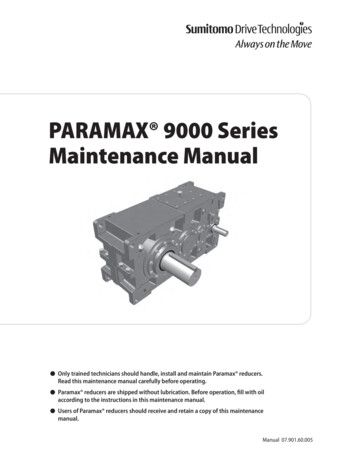
6.0.0System with Remote Indoor Tank Operation6.1.0No water is to be left in outdoor lines. Cold weather conditions will quickly freezeany standing water which may result in burst pipes.6.2.0The cooling tower must be elevated to a height above the indoor tank level. Thisallows the cooling tower to drain through the return line by gravity back to theindoor tank.6.3.0Typically, a bleed-off line (1/2" nominal diameter) is installed indoors, betweenthe cooling tower inlet piping (4" supply line) and the cooling tower outlet piping(8" return line) so that all external piping can be emptied during a systemshutdown period. See drawing below for further details.6.4.0In a multiple cooling tower system, there will be multiple cooling tower supplylines. In this case, it is very important to provide independent bleed-off lines foreach circuit. Separate bleed-off lines instead of a common bleed-off line willeliminate the possibility of feeding water from an operating circuit to a nonoperating circuit. See diagram below for further details.
6.5.0In a single-pump systems with a remote indoor tank, it is recommended that athree-way valve be installed in the cooling tower supply line. This allows bypassof the cooling tower in times of low load.The three-way valve cannot be of the modulating type.
7.0.0Cold Weather Operation7.1.0In regions where the ambient temperature drops below the freezing point forwater, cold weather operation of the cooling tower has certain requirements to bemet.7.1.1A basin heater or equivalent to provide protection against the water freezing inthe cooling tower basin during shutdown situations in cold weather conditions.7.2.0All outdoor piping leading to and from the cooling tower should be wrapped withheat tracing cable and insulated to prevent freezing cold weather conditions.7.3.0Capacity can be controlled by means of fan cycling. However, cycling increasesthe fan motor temperature which over a period which can reduce the life of thefan motor, so caution must be exercised.7.4.0The cooling tower should be checked on a regular basis, with emphasis on areaswhere there is stagnant water or low water levels may appear.
8.0.0Cooling Tower Internals8.1.0Fibreglass Shell and BasinConstruction of the shell and basin is of chipped glass-resin spray up. The glassreinforcement used is commercial grade type E glass fibre with an iophthaliocpolyester-coupling agent. The outer layer is a 15/20 mil. thick gel coat compoundwith UV (Ultraviolet) inhibitors.8.2.0Fill/Wet DeckBerg cooling tower fill is manufactured from rigid PVC (Polyvinyl Chloride)developed especially for counter flow cooling tower applications where thecontinuous operating water temperature is to be 130 oF or less.8.3.0Internal Support Structures
All internal cooling tower support structures, fan motor bracket, fasteners, andhardware are constructed from 304 stainless steel.8.4.0Air Inlet LouversBerg air inlet louvers are manufactured from rigid PVC especially formulated forUV resistance, low maintenance, with a 45o inward slant towards the coolingtower basin to prevent water loss.8.5.0Fan MotorAll motors are TEFC (Totally Enclosed Fan Cooled) NEMA design B (IP55), classF insulation, 900 RPM, 80 oC temperature rise with a 1.15 service factor. SeeMotor Section at end of manual for further details.8.6.0Axial FanAll fans are propeller type, 60" diameter, 900 RPM, high efficiency, quiet design,with a clockwise-only direction.8.7.0Drift EliminatorBerg cooling tower drift eliminator are manufactured from rigid PVC developedespecially for counter flow cooling tower applications with a low pressure drop,high droplet trapping design.8.8.0Water DistributionBerg cooling tower nozzles are non-clogging, vertical down, square spray, withno moving parts.8.9.0Lifting LugsEach lifting lug has an internal eye diameter of 1" with a rated maximum verticalcapacity of 2,400 lb. per lug.
9.0.0Maintenance9.1.0The cooling tower should be checked regularly. See Figure 9.1 below for arecommended maintenance schedule.9.2.0Before any maintenance is performed on the cooling tower, make sure that allpower to cooling tower components is disconnected and locked out.9.3.0A water treatment program to stop biological contamination and the creation ofconditions conducive to the development of legionnella bacteria is strongly urgedwith any cooling tower system. Also, a water bleed-off and full flow filter systemare recommended to control dissolved solids and turbidity in the system9.4.0If a chemical treatment system is being used, check operation of water treatmentin the cooling tower system, operation of automatic chemical treatment unit, andoperation of both the bleed-off and bleed-back lines on a regular basis.Please contact the local Berg Chilling Systems Inc.representative before any chemical treatment package is installed toensure compatibility. Failure to do so can cause internal erosion andFRP degradation, which will in turn result in a severely damaged andunsafe cooling tower.9.5.0Water conditions should be checked periodically. The water should be clean aspossible since dirty water can cause excessive pump seal wear.9.6.0All fasteners should be checked for tightness and re-tightened where applicablewith care taken not to over-torque the fasteners. This is a natural function of theFRP settling after installation and transportation.9.7.0Fan motor bearings should be checked for noise and lubrication. Use only goodquality lithium base or lithium complex grease with a base oil viscosity of 100 140 c St @ 40 oC, consistency NLGI grade 2 or 3 and a continuous temperaturerange of -30 oC to 130 oC. See motor specifications at the end of the manual forfurther details.9.8.0All external pipe hangers should be checked regularly for the proper tension andthat they are still securely tied down.9.9.0Spray nozzles should be checked periodically to ensure that the spray remains atoriginal full shape and that the flow rate through each nozzle is approximately thesame. A blown out nozzle can quickly result in the destructive erosion of thefill/wet deck.
9.10.0The air inlet louvers and the air outlet discharge should both be checkedperiodically to make sure there are no obstructions or blockages. Blockagescreate regions of high air velocity and this results in inefficient cooling towerperformance.
Figure 9.1 : Maintenance ScheduleServiceStartupMonth6MonthAnnualGeneral inspectionXXInspect UV external coatingXXClean debris from basinXXFlush basin w/ clean waterXXRe-tighten all fastenersXXInspect fill/wet deckXXCheck air inlet louversXXCheck bleed-off rateXXCheck water qualityXXCheck vibration levelsXXCheck noise levelsXXCheck water conditionsXXCheck water treatmentXXCheck motor voltage ¤tXXCheck air outlet dischargeXXCheck for bushing slippageXXInspect pipe hangersXXCheck fan rotationXInspect spray nozzlesLubricate fan motor bearingsXAs per WEG ManualOther
Recommended Spare PartsItem DescriptionSuggestedQuantitySpray nozzle, type 1-D4Fan motor1Fan blade1Split taper bushing1Make-up water valve(option)1Basin heater (option)1Low level switch (option)1Note :These are only suggested parts and quantities. These items are stocked at theBerg Chilling Systems Inc. manufacturing facility. For pricing and availability,contact the local Berg Chilling Systems Inc. representative.
10.0.0Air Conditioning Connections (Option)10.1.0The air conditioning connections consist of a 2” overflow, a 1” quick fill and a ¾”make-up valve assembly. This option will be factory mounted, no field assemblyis required.A/C CONNECTIONS LOCATION10.2.0This option allows the system to use cooling tower basin as a water reservoir.This is only recommended for warm climate process cooling or summer airconditioning condenser water applications. For cold weather operation, pleasefollow section 7 (p.17) very carefully. Failure to do so may result in burstoutdoor pipes and cracked tower basin.10.3.0The make-up valve assembly is a float operated mechanical device whichmaintains the water level in the tower basin. It is located inside the basin. It canbe accessed by removing the intake louvre directly above the valve assembly.
10.4.0The make-up valve assembly consists of a bronze make-up valve connected to aserrated arm assembly and is actuated by a 6” diameter plastic float. The float isconnected to the serrated arm via a bronze stem. The operating water level inthe basin can be adjusted by rotating the serrated arm upwards or downwards.MAKE-UP VALVE ASSEMBLY10.5.0Before setting the basin water level, remove any packing material from the plasticfloat and examine for any signs of shipping damage.10.6.0To set the initial basin water level, adjust the serrated arm so that the make-upvalve is completely closed when water level is approximately ¾” below theoverflow connection. The operating water level should be set at approximately 1”above the 8” basin outlet.10.7.0The make-up valve assembly should be inspected monthly and adjusted asnecessary. The valve itself should be inspected annually and the valve sealreplaced if necessary.
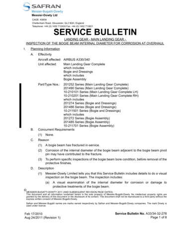
11.6.0Basin Heater (Option)11.1.0This option includes a 12KW pipe thread horizontal immersion heater and a liquidlevel float switch. The heater and the float switch will be shipped loose and fieldassembly is required.11.2.0The basin heater has a 2” NPT brass connection fitting and has copper heatingelements. It has a NEMA 4 terminal box with a built in 0-100 F pilot dutythermostat.11.3.0The liquid level float switch is a mechanical device used to monitor the waterlevel above the heating elements. It has a NEMA 3R raintight enclosure and a 1”NPT pipe connector. If the water level falls to within 1” above the heatingelements, the switch will shut down the heater to prevent hazardous overheatwhich would result in heater burn out.TYPICAL WIRING DIAGRAM11.4.0To facilitate the field mounting of the basin heater and the liquid level float switch,holes were drilled by factory before shipping.HOLES LOCATION
11.5.0First remove the two louvers located directly above the water outlet. Thenremove the lock nut and rubber gasket from the heater and liquid level switchassembly. Insert the heater and the level switch into the pre-drilled holes fromthe front. Replace the gasket and lock nut from inside the basin. Tighten thelock nut against the bulkhead fitting and ensure that no leaks are evident.BASIN HEATERLIQUID LEVEL FLOAT SWITCH
11.6.0Field installation detailsBASIN HEATER INSTALLATION DETAILS11.7.0Care should be taken not to nick or damage the thread when lifting or moving thebasin heater and the liquid level switch. Do not lift heater just by the heatingelements. Exercise care when installing the heater and the liquid level floatswitch so as not to damage heating elements or the float.11.8.0Check all electrical connections, including field and factory made, for tightness atleast once a year. Keep heating elements clean. Do not allow sludge to build onelements. Check the liquid level float switch to insure it is functioning properly.
Limited WarrantyBerg Chilling Systems Inc. (“Berg”) warrants to Buyer that upon delivery to Buyer the Productspurchased hereunder shall conform to the applicable Seller’s specifications as provided in thequotation. Except as are contained herein, Berg makes no warranties, conditions, guaranteesor representations relating to the Products, express or implied, statutory or otherwise. TheSeller warrants all Products it manufactures to be free from defects in workmanship andmaterial when used under conditions recommended by us. The Seller’s obligation under thewarranty is limited to repair or replace or otherwise make good, at our factory, any parts which,within one year after date of shipment of equipment of our manufacture to the originalpurchaser, after being returned to us with transportation prepaid, and upon our examination,shall disclose to our satisfaction to have been defective. The Seller neither assures, norauthorizes any other persons to assume for us, any liability in connection with the sales of ourequipment except under the conditions of this warranty. The warranty does not cover any field(on site) labour charges for replacement of parts, adjustment, repairs, or any other work done.This warranty shall not apply to any Product or apparatus which in our opinion has beensubject to misuse, negligence, or pressures in excess of limits recommended by us, or whichhave been repaired or altered outside Berg’s factory or which have had the serial number(s)removed or defaced. This warranty does not cover refrigerant gas, nor does it cover anyapparatus damaged from freezing of water or heat transfer fluid. Replacement or repair ofdefective material will be EX WORKS our factory, and will assume any used portion of thiswarranty. All defective parts become the property of Berg and must be returned within fifteen(15) days of the replacement date, transportation prepaid, as advised by Berg, to becomeeligible for replacement under this warranty. Warranty Claim Forms, found in the ProductOwner’s Manual, must accompany all warranty claims and parts returns or this warranty shallnot apply. Berg is not responsible for any sales, use, excise, duty or any other applicabletaxes associated with the replacement of parts under this warranty. This warranty is onlyeffective with all the terms and conditions of the Product quote being met, and it is understoodthat time is of the essence in this agreement. Repair or replacement of products not of ourmanufacture will be limited to the warranty of the manufacturers of such products. Seller shalltransfer to Buyer whatever transferable warranties and indemnities Seller receives from themanufacturers of any subcomponents of the Products, if any, including any transferablewarranties and indemnities in respect of patent infringement. See the Product Service LabourPolicies in your Product Owner’s Manual for possible extensions to this Warranty.This is an expressed warranty of merchantability and or fitness for a particular purpose; allother implied warranties and any liabilities not based upon contract are hereby disclaimed andexcluded by this warranty.In accordance with Section 7 of our Standard Terms and Conditions of Sale, under nocircumstances shall Berg Chilling Systems Inc. be liable for loss of prospective or speculativeprofits, or special, indirect, incidental, or consequential damages.This warranty is a part of the Standard Terms and Conditions of Sale of Berg Chilling SystemsInc.
Service Labour PolicyBerg’s Service Labour Policy extends the One (1) Year Limited Warranty to include labour on alimited basis, to the original purchaser only (see the Limited Labour Allowance Schedule inyour Product Owner’s Manual for allowable service hours). Berg will provide a ServiceTechnician or reimburse the Buyer in accordance with this Policy, to diagnose the problem,repair or replace or otherwise make good, any part of equipment of our manufacture, whichwithin one year after the date of shipment to a destination within Canada or continental UnitedStates of America (“the Territory”), and upon our examination, shall disclose to our satisfactionto have been defective. If the Product or equipment is located outside “the Territory”, ourlimited warranty only, ex works our factory, shall apply for one year from the date of shipping(see Standard Terms and Conditions of Sale). Berg neither assures, nor authorizes any otherpersons to assume for us, any liability in connection with the sale of our equipment exceptunder the conditions of this Policy. This Service Labour Policy does not apply to TemperatureControl Units (TCU’s).The Service Labour Policy does not cover any field (on site) labour charges during overtimehours (5:00pm to 8:00am or during weekends and holidays) nor does it cover charges, labouror otherwise, associated with travel and accommodation, adjustments and maintenance, orwork done outside of Canada and continental USA. Any cost differential for overtime labourcharges will be the responsibility of the Buyer. Service Labour rates applied to the LimitedLabour Allowance Schedule, will be the mean rate, as determined by Berg, of the equipmentdestination service area.This Policy is voided and shall not apply if in our opinion, the Product has been subject tomisuse, negligence, or pressures in excess of limits recommended by Berg, or which havebeen repaired or altered outside Berg’s factory or authorization or which have had the serialnumber(s) removed or defaced. This Policy does not cover refrigerant gas or any labourassociated with its evacuation or replacement nor does it cover any Product or apparatusmaintenance or any apparatus damaged from freezing of water or heat transfer fluid. Anywork determined to be associated with the above will be the responsibility of the Buyer.Berg is not responsible for any sales, use, excise, duty or any other applicable taxesassociated with the replacement of parts or labour under this Policy. This Policy is onlyeffective with all the terms and conditions of our quote being met, and it is understood that timeis of the essence in this agreement. This Policy is not transferable.All Service Policy Labour must be authorized by Berg prior to any work being performed andmust have a Berg Purchase Order issued specifically for the work. Warranty and ServiceLabour Claim Forms, found in the Product Owner’s Manual, must accompany all Service andWarranty claims and parts returns or this Policy shall not apply. All defective parts become theproperty of Berg and must be returned within fifteen (15) days of the failure, transportationprepaid, as advised by Berg, to become eligible for replacement under this policy.Products not of our manufacture do not qualify for this Service Labour Policy, and will belimited to the warranty of the manufacturers of such Products.
This Policy is a part of the Standard Terms and Conditions of Sale of Berg Chilling SystemsInc.
Warranty Claim ProcedureLabour warranty, will only be allowed in those situations where defects have occurred as adirect result of factory workmanship or defects in materials.Claim Procedures: Consult the Factory immediately of any problems you are having with your equipment.Phone 416-755-2221 or fax 416-755-6022. If required Berg will supply contact information for the local authorized Berg ServiceContractor in your area; or if you wish you can use your own contractor, provided he islicensed and qualified as required by local governing authorities and it is agreed uponby Berg. After the contractor has arrived on site and determined the cause of the problem; thecontractor must consult with the factory before proceeding with any repairs. Once you have had your equipment repaired, complete the “Warranty Claim Form.” Allclaims must be submitted on the Warranty Claim Form” found in the owners manual. A signed service report from the Contractor detailing all work performed and an invoicecopy must accompany the “Warranty Claim Form.” Claims must be faxed to “Berg Service Department” @ 416-755-6022 no later than 15days after the failure has occurred. Claims in excess of the ”Limited Labour Allowance Schedule” may not be processed. Berg reserves the right to adjust and/or refuse any claims that appear excessive or failsto meet the Claims Procedure. No claims wi
allows the cooling tower to drain through the return line by gravity back to the indoor tank. 6.3.0 Typically, a bleedoff line (1/2" nominal diameter) is installed indoors, between - the cooling tower inlet piping (4" supply line) and the cooling tower outlet piping (8" return line) so that all external piping can be emptied during a system