Transcription
POWER STEERING – POWER STEERING SYSTEMPS–1POWER STEERING SYSTEMPRECAUTION1.2.HANDLING PRECAUTIONS FOR SRS AIRBAGSYSTEM (SEE PAGE RS-1)NOTICE:Some service operations affect the SRS airbag. Besure to read the precautionary notice for the SRSairbag before servicing.PRECAUTIONS FOR REMOVAL, INSTALLATION ANDREPLACEMENT OF ELECTRONIC MOTOR POWERSTEERING COMPONENTS(a) Be sure to align the front wheels straight aheadwhen removing and installing the steering gearassembly.(b) When disconnecting the sliding yoke of the steeringcolumn and the pinion shaft of the steering gearassembly, be sure to put matchmarks beforestarting the operation.(c) When any component related to the steering systemhas been removed and either reinstalled orreplaced, perform the steering center pointadjustment (zero point calibration) (see page RS31).(d) When disconnecting the connector related to theelectronic motor power steering wheel, turn thepower switch ON (IG) (the engine and the hybridsystem are not stopped), center the steering wheel,turn the power switch OFF, and then disconnect theconnector.(e) When reconnecting the connector related to theelectronic motor power steering system, ensure thatthe power switch is OFF. Center the steering wheeland then turn the power switch ON (IG) (the engineand the hybrid system are not stopped).NOTICE:Do not turn the power switch ON (IG) (the engineand the hybrid system are not stopped) whenthe steering wheel is not centered.(f) If the procedures above are not performed outproperly, the steering center point (zero point) willdeviate, which may lead to a difference in steeringeffort between right and left. If there is a differencein steering effort between right and left, perform thesteering center point adjustment (zero pointcalibration) (see page RS-31).NOTICE:FOR INITIALIZATIONWhen disconnecting the cable from the negative(-) battery terminal, initialize the followingsystems after the cable is reconnected.System NameSee PagePower Window Control SystemIN-32PS
PS–2POWER STEERING – POWER STEERING SYSTEMNOTICE:FOR HYBRID SYSTEM ACTIVATION When the warning light is illuminated or thebattery has been disconnected andreconnected, pressing the power switch maynot start the system on the first try. If so,press the power switch again. With the power switch's power modechanged to ON (IG), disconnect the battery. Ifthe key is not in the key slot duringreconnection, DTC B2799 may be output.PS
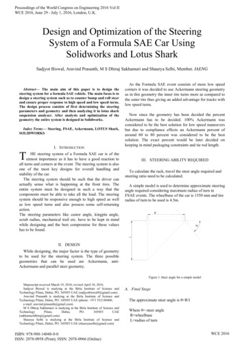
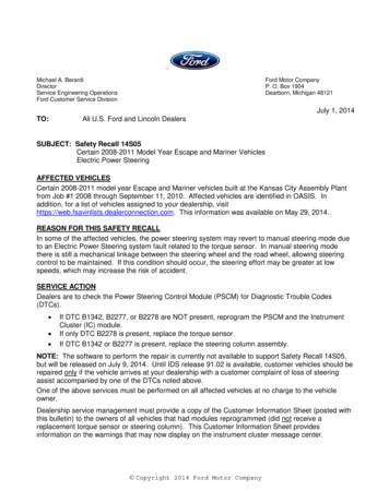
PS–3POWER STEERING – POWER STEERING SYSTEMSYSTEM DESCRIPTION A rack and pinion type steering gear is used on all models. The PRIUS uses a vehicle-speed sensing type EPS(Electric Power Steering) on all models.Power Steering ECUSteering WheelPower Steering MotorSteering ColumnSteering GearECUPOWER STEERINGTORQUE eelG100841E03PS
PS–4POWER STEERING – POWER STEERING SYSTEMPROBLEM SYMPTOMS TABLEHINT:Use the table below to help determine the cause of theproblem. The potential causes of the symptoms are listed inorder of probability in the "Suspected area" column of thetable. Check each symptom by checking the suspected areasin the order they are listed. Replace parts as necessary.Steering SystemSymptomSteering is heavy.Steering effort differs between right and left or isuneven.While driving, steering effort does not change inaccordance with vehicle speed or steering wheel doesnot return properly.See page1. Front tires (improperly inflated, unevenly worn)TW-32. Front wheel alignment (Incorrect)SP-23. Front suspension (Lower ball joint)SP-244. Steering gearPS-495. Torque sensor (built into steering column)-6. Steering columnSR-77. Power steering motorSR-78. Battery and power source system-9. Power steering ECUSR-161. Steering center point (zero point) (not recorded completely)PS-132. Front tires (improperly inflated, unevenly worn)TW-33. Front wheel alignment (Incorrect)SP-24. Front suspension (Lower ball joint)SP-235. Steering gearPS-496. Torque sensor (built into steering column)-7. Steering columnSR-78. Power steering motorSR-79. Power steering ECUSR-161. Front suspensionSP-22. Speed sensor-3. Skid control ECUBC-2294. Combination meter-5. Engine speed detection circuit-6. Torque sensor (built into steering column)-7. Power steering motorSR-78. Power steering ECUSR-161. Front suspensionSP-22. Steering intermediate shaft-3. Steering gearPS-49Friction sound occurs when turning steering wheelduring low speed driving.1. Power steering motorSR-72. Steering columnSR-7High-pitched sound (squeaking) occurs when turningsteering wheel slowly with vehicle stopped.1. Power steering motorSR-7Steering wheel vibrates and noise occurs when turningsteering wheel from lock to lock.1. Power steering motorSR-72. Steering columnSR-7Knocking (or clunking) sound occurs when turningsteering wheel back and forth while power steering isin operation.PSSuspected area
POWER STEERING – POWER STEERING SYSTEMPS–5ON-VEHICLE INSPECTION1.CHECK STEERING EFFORT (TORQUE)NOTICE:Some service operations affect the SRS airbag. Besure to read the precautionary notice for the SRSairbag before servicing.(a) Stop the vehicle on a level, paved road and align thewheels straight ahead.(b) Disconnect the cable from the negative (-) batteryterminal.(c) Remove the steering pad (see page RS-267).(d) Connect the cable to the negative (-) batteryterminal.(e) Using a torque wrench, check if the steering wheelset nut is properly tightened.Torque: 50 N*m (510 kgf*cm, 37 ft.*lbf)(f) Turn the power switch ON (IG) (the engine and thehybrid system are not operated) so that powersteering is ready to operate.(g) Turn the steering wheel 90 degrees to the right andcheck steering effort (torque) while turning. Check inthe opposite direction using the same procedure.Steering effort (Reference):5.5 N*m (56 kgf*cm, 49 in.*lbf)(h) Align the front wheels straight ahead.(i) Disconnect the cable from negative (-) batteryterminal.(j) Install the steering pad assembly (see page RS268).(k) Connect the cable to the negative (-) batteryterminal.(l) Clear the DTCs (see page RS-38).(m) Perform initialization (see page IN-32).(n) Inspect the airbag warning light (see page RS-31).G029440E022.CHECK STEERING WHEEL FREE PLAY(a) Turn the power switch ON (IG) so that powersteering is ready to operate.(b) Align the wheels straight ahead.(c) Gently turn the steering wheel right and left withyour finger and check the steering wheel free play.Maximum free play:30 mm (1.18 in.)If the free play is out of specification, replace thesliding yoke sub-assembly or steering gearassembly with a new one.PS
PS–6POWER STEERING – ELECTRONIC POWER STEERING SYSTEMELECTRONIC POWER STEERINGSYSTEMPRECAUTION1.PSFOR INITIALIZATIONNOTICE:When disconnecting the cable from the negative (-)battery terminal, initialize the following systems afterthe cable is reconnected.System NameSee procedurePower Window Control SystemIN-322. FOR HYBRID SYSTEM ACTIVATIONNOTICE: When the warning light is illuminated or the batteryhas been disconnected and reconnected, pressing thepower switch may not start the system on the first try.If so, press the power switch again. With the power switch's power mode changed to ON(IG), disconnect the battery. If the key is not in the keyslot during reconnection, DTC B2799 may be output.3. HANDLING PRECAUTIONS(a) When handling the electronic parts:(1) Avoid any impact to electronic parts such asECUs and relays. Replace the parts with newones if dropped or subjected to a severe impact.(2) Do not expose any electronic parts to hightemperature and humidity.(3) Do not touch the connector terminals in order toprevent deformation or malfunctions due tostatic electricity.(4) When the power steering ECU has beenreplaced with a new one, perform the torquesensor zero point calibration (see page PS-13).(b) When handling the steering column:(1) Avoid any impact to the steering column,especially to the motor or torque sensor.Replace the parts with new ones if dropped orsubjected to a severe impact.(2) Do not pull on the wire harness when moving thesteering column.(3) When the steering column has been replaced,perform the torque sensor zero point calibrationafter initializing the torque sensor zero pointcalibration signal (see page PS-13).(c) When disconnecting and reconnecting theconnectors:(1) When disconnecting a connector related to theelectric power steering system, turn the powerswitch ON (IG), center the steering wheel, turnthe power switch OFF, and then disconnect theconnector.
POWER STEERING – ELECTRONIC POWER STEERING SYSTEM4.PS–7(2) When reconnecting a connector related to theelectric power steering system, ensure that thepower switch is OFF. Center the steering wheeland then turn the power switch ON (IG).NOTICE:Do not turn the power switch ON (IG) whenthe steering wheel is not centered.(3) If the above operations are not carried outproperly, the steering center point (zero point)will deviate, which may lead to a difference inright and left steering effort. If there is adifference in right and left steering effort, performthe torque sensor zero point calibration (seepage PS-13).PRECAUTIONS FOR CAN COMMUNICATION(a) CAN communication is used to receive informationfrom the skid control ECU and to transmit warningsto the meter and the multi-display. When there areany problems in the CAN communication lines,DTCs indicating the communication linemalfunctions are output.(b) Perform troubleshooting for the communication lineproblems when the CAN communication DTCs areoutput. Be sure to start troubleshooting on theelectronic power steering system when datacommunication is normal.(c) A temporary fix or repair with bypass wiring, etc. isimpossible because the length and path of eachCAN communication line is specific.PS
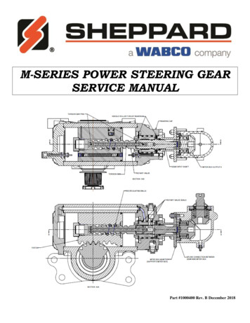
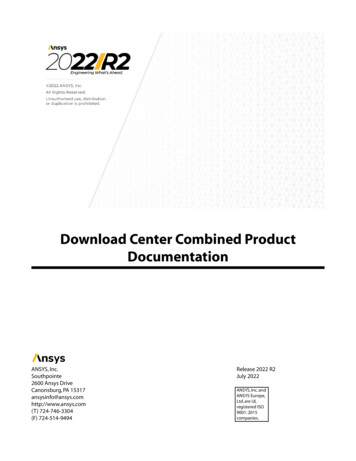
PS–8POWER STEERING – ELECTRONIC POWER STEERING SYSTEMPARTS LOCATIONSTEERING COLUMN ASSEMBLY- TORQUE SENSOR- POWER STEERING MOTORENGINE ROOM JUNCTION BLOCK- EPS FUSEPSF100806E01
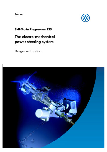
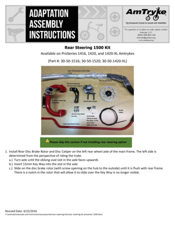
POWER STEERING – ELECTRONIC POWER STEERING SYSTEMPS–9MULTI-DISPLAYPOWER STEERING ECUDLC3DRIVER SIDE JUNCTION BLOCK- IG1 RELAY- ECU-IG FUSEF100807E01PS
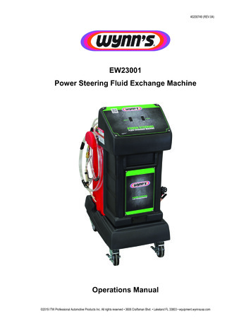
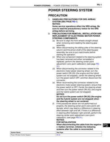
PS–10POWER STEERING – ELECTRONIC POWER STEERING SYSTEMSYSTEM DIAGRAM12 VPower Switch: CAN: BEANPower SteeringMotorTorque Sensor: Input signal to powersteering ECU: Output signal from powersteering ECUPower SteeringECUDLC3Gateway ECUHybrid Vehicle Control ECUSkid Control ECUBody ECU: Destination signal: ECB system troublesignal: Shift information signal: Vehicle model signal: Stop light switch signal: Ready condition signal: Vehicle speed signal: Grade packageinformation signal: Power use permissible signal: EPS mass current controlling signal: Steering angle information signalCombination Meter: EPS light ONsignalPS)F100808E04
POWER STEERING – ELECTRONIC POWER STEERING SYSTEMPS–11SYSTEM DESCRIPTION1.DESCRIPTION(a) The electronic power steering system generatestorque through the operation of the motor and thereduction gear installed on the column shaft in orderto assist steering effort.Directions and amount of assisting power aredetermined by signals from the torque sensor builtinto the steering column assembly and by the powersteering ECU, and controlled in accordance withvehicle speed. As a result, steering effort iscontrolled to be light during low speed driving andmoderately high during high speed driving.(1) Power steering ECU:The power steering ECU calculates assistingpower based on a steering torque signal fromthe torque sensor and a vehicle speed signalfrom the skid control ECU. It generates specifiedassisting torque by controlling current to themotor.(2) Torque sensor:The torque sensor detects steering effortgenerated when the steering wheel is turnedand converts it to an electrical signal.(3) Power steering motor:The power steering motor is activated by thecurrent from the power steering ECU andgenerates torque to assist steering effort.PS
PS–12POWER STEERING – ELECTRONIC POWER STEERING SYSTEMHOW TO PROCEED WITHTROUBLESHOOTINGHINT: Use these procedures to troubleshoot the ElectronicPower Steering System (EPS). *: Use the intelligent tester.1VEHICLE BROUGHT TO WORKSHOPNEXT2INSPECT BATTERY VOLTAGEStandard voltage:11 to 14 VIf the voltage is below 11 V, recharge or replace the batterybefore proceeding.NEXT3CHECK DTC AND FREEZE FRAME DATA*(a) Record DTCs (see page PS-23) and freeze frame data(see page PS-23).NEXT4PROBLEM SYMPTOM CONFIRMATIONResultResultProceed toSymptom does not occurASymptom occursBBGo to step 6A5SYMPTOM SIMULATIONNEXT6PSCHECK CAN COMMUNICATION SYSTEM*(a) Check for DTCs.ResultResultProceed toCAN system DTC is not output.A
POWER STEERING – ELECTRONIC POWER STEERING SYSTEMResultProceed toCAN system DTC is output.BPS–13HINT: When any CAN communication system DTCs areoutput, perform troubleshooting on the CANcommunication system first (see page CA-8). When communication to the power steering ECU isnot established through the intelligent tester, inspectterminals SIL of the DLC3 and power steering ECUand inspect the IG circuit of the power steering ECU.BPROCEED TO CAN COMMUNICATIONSYSTEMA7CHECK DTC*(a) Check for a DTCs.ResultResultProceed toDTC is not output.ADTC is output.BBGo to step 11A8PROBLEM SYMPTOMS TABLENEXT9CIRCUIT INSPECTIONNEXT10IDENTIFICATION OF PROBLEMNEXT11NEXTREPAIR OR REPLACEPS
PS–1412NEXTENDPSPOWER STEERING – ELECTRONIC POWER STEERING SYSTEMCONFIRMATION TEST
POWER STEERING – ELECTRONIC POWER STEERING SYSTEMPS–15CALIBRATION1.INITIALIZATION OF TORQUE SENSOR ZERO POINTCALIBRATION SIGNALNOTICE:Under the following conditions, perform the torquesensor zero point calibration after initializing thetorque sensor zero point calibration signal in theECU: The steering column (containing the torquesensor) has been replaced. The power steering ECU has been replaced. The steering wheel has been replaced. The steering gear assembly has been replaced. There is a difference in right and left steeringeffort.(a) Center the steering wheel and align the front wheelsstraight ahead.(b) Connect the intelligent tester (with CAN VIM) to theDLC3.(c) Turn the power switch ON (IG) and then initialize thetorque sensor zero point calibration signal byfollowing the directions on the tester screen.NOTICE:Do not turn the steering wheel while initializingthe zero point calibration signal.(d) Perform steering zero point calibration after turningthe power switch OFF.NOTICE:Zero point calibration cannot be carried out withthe power switch ON (IG) after initialization ofthe zero point calibration signal is completed.PS
PS–16)PSPOWER STEERING – ELECTRONIC POWER STEERING SYSTEMF100818
POWER STEERING – ELECTRONIC POWER STEERING SYSTEM)PS–17F1008192.TORQUE SENSOR ZERO POINT CALIBRATION(a) Center the steering wheel and align the front wheelsstraight ahead.(b) Connect the intelligent tester (with CAN VIM) to theDLC3.PS
PS–18POWER STEERING – ELECTRONIC POWER STEERING SYSTEM(c) Turn the power switch ON (IG) and then perform thezero point calibration by following the directions onthe tester screen.NOTICE: The vehicle is stopped. Do not start the engine. (Do not turn thepower switch ON (READY).) Do not turn the steering wheel. The vehicle is on level ground.(d) Confirm that no DTCs are output after completingthe operation.(1) When DTC C1515 is output, refer to thefollowing procedures (see page PS-32).(2) When DTC C1516 is output, refer to thefollowing procedures (see page PS-33).(3) When DTC C1534 is output, refer to thefollowing procedures (see page PS-36).PS
POWER STEERING – ELECTRONIC POWER STEERING SYSTEM)PS–19F100820PS
PS–20)PSPOWER STEERING – ELECTRONIC POWER STEERING SYSTEMF100821
PS–21POWER STEERING – ELECTRONIC POWER STEERING SYSTEMPROBLEM SYMPTOMS TABLEHINT:Use the table below to help determine the cause of theproblem symptom. The potential causes of the symptoms arelisted in order of probability in the "Suspected area" column ofthe table. Check each symptom by checking the suspectedareas in the order they are listed. Replace parts asnecessary.Electronic power steering systemSymptomSteering is heavySteering effort differs between right and left or isunevenWhile driving, steering effort does not change inaccordance with vehicle speed or steering wheel doesnot return properlySuspected areaSee page1. Front tires (Improperly inflated, unevenly worn)TW-32. Front wheel alignment (Incorrect)SP-23. Front suspension (Lower ball joint)SP-244. Steering gearPS-525. Torque sensor (built into steering column)PS-326. Steering columnSR-117. Power steering motorPS-378. Battery and power source system-9. Power source voltage of power steering ECUPS-4410.Power steering ECUSR-161. Steering center point (zero point) is not recorded completelyPS-132. Front tires (Improperly inflated, unevenly worn)TW-33. Front wheel alignment (Incorrect)SP-24. Front suspension (Lower ball joint)SP-245. Steering gearPS-526. Torque sensor (built into steering column)PS-327. Steering columnSR-118. Power steering motorPS-379. Power steering ECUSR-161. Front suspension-2. Speed sensorBC-2183. Skid control ECUBC-2294. Engine speed detection circuit-5. ECMES-4696. Torque sensor (built into steering column)PS-327. Power steering motorPS-378. Power steering ECUSR-169. CAN communication systemCA-81. Front suspension-2. Steering intermediate shaft-3. Steering gearPS-52Friction sound occurs when turning steering wheelduring low speed driving1. Power steering motorPS-372. Steering columnSR-11High-pitched sound (squeaking) occurs when turningsteering wheel slowly with vehicle stoppedPower steering motorPS-37Steering wheel vibrates and noise occurs when turningsteering wheel with the vehicle stopped1. Power steering motorPS-372. Steering columnSR-111. Power steering ECUSR-162. Wire harnessPS-443. CAN communication systemCA-84. Multi-displayNS-172Clunking sound occurs when turning steering wheelback and forth while power steering is in operationPS warning is always indicated on multi-displayPS
PS–22POWER STEERING – ELECTRONIC POWER STEERING SYSTEMTERMINALS OF ECU1.CHECK POWER STEERING ECUP8P7P10P9F044303E04(a) Measure the voltage and resistance of theconnectors.Symbols (Terminal No.)Wiring ColorTerminal DescriptionConditionSpecified ConditionPIG (P7-1) - PGND (P7-2)W - W-BPower sourceAlways10 to 16 VPGND (P7-2) - BodygroundW-B - Body groundPower groundAlwaysBelow 1 ΩM1 (P9-1) - PGND (P7-2)R - W-BPower steering motorsignalWith power switch ON(IG), turn the steeringwheel to leftBelow 1 VWith power switch ON(IG), turn the steeringwheel to right10 to 16 VWith power switch ON(IG), turn the steeringwheel to left10 to 16 VWith power switch ON(IG), turn the steeringwheel to rightBelow 1 VM2 (P9-2) - PGND (P7-2)PSB - W-BPower steering motorsignalCANH (P8-1) - CANL (P87)B-WCAN communication linePower switch is OFF54 to 69 ΩSIL (P8-2) - PGND (P7-2)W - W-BDiagnosis communicationsignalCommunication isestablished by connectingthe intelligent tester (withCAN VIM) to the DLC3Pulse generation (seewaveform 1)IG (P8-6) - PGND (P7-2)B - W-BIG power sourcePower switch is ON (IG)10 to 16 VTRQ1 (P10-5) - PGND(P7-2)B - W-BTorque sensor signalWith power switch ON(IG), turn the steeringwheel to left and right0.3 to 4.7 VTRQV (P10-6) - PGND(P7-2)Y - W-BTorque sensor voltagesourcePower switch ON (IG)7.5 to 8.5 VTRQ2 (P10-7) - PGND(P7-2)R - W-BTorque sensor signalWith power switch ON(IG), turn the steeringwheel to left and right0.3 to 4.7 VTRQG (P10-8) - PGND(P7-2)W - W-BTorque sensor groundAlwaysBelow 1 Ω
POWER STEERING – ELECTRONIC POWER STEERING SYSTEMPS–23(b) Using an oscilloscope, check waveform 1.Waveform 1 (Reference)Waveform 1TerminalSIL - Body groundTool setting5 V/DIV, 1 ms/DIVConditionCommunication is established byconnecting the intelligent tester (withCAN VIM) to the DLC3HINT:If the result is not as specified, the ECU may have amalfunction.C081996E05DIAGNOSIS SYSTEM1.CGSGCANHSILCHECK DLC3The vehicle's ECU uses the ISO 15765-4 communicationprotocol. The terminal arrangement of the DLC3complies with ISO 15031-03 and matches the ISO15765-4 format.1 2 3 4 5 6 7 89 10 11 12 13 14 15 16CANLBATB126621E01Symbols (Terminal No.)Terminal DescriptionConditionSpecified ConditionSIL (7) - SG (5)Bus " " lineDuring transmissionPulse generationCG (4) - Body ground ChassisgroundChassis groundAlwaysBelow 1 ΩSG (5) - Body ground SignalgroundSignal groundAlwaysBelow 1 ΩBAT (16) - Body groundBattery positiveAlways11 to 14 VCANH (6) - CANL (14)HIGH-level CAN bus linePower switch is OFF*54 to 69 ΩCANH (6) - Battery positiveHIGH-level CAN bus linePower switch is OFF*1 MΩ or higherCANH (6) - CG (4)HIGH-level CAN bus linePower switch is OFF*1 kΩ or higherCANL (14) - Battery positionLOW-level CAN bus linePower switch is OFF*1 MΩ or higherCANL (14) - CG (4)LOW-level CAN bus linePower switch is OFF*1 kΩ or higherNOTICE:*: Before measuring the resistance, leave the vehicleas is for at least 1 minute and do not operate theignition switch, other switches or the doors.If the result is not as specified, the DLC3 may have amalfunction. Repair or replace the harness andconnector.PS
PS–24POWER STEERING – ELECTRONIC POWER STEERING SYSTEMIntelligent TesterDLC3CAN VIM2.B126098E01DTC CHECK / CLEARIntelligent Tester1.2.DLC3CAN VIMB126098E01PSHINT:Connect the cable of the intelligent tester (with CANVIM) to the DLC3, turn the power switch ON (IG) andattempt to use the tester. If the display indicates that acommunication error has occurred, there is a problemeither with the vehicle or with the tester. If communication is normal when the tester isconnected to another vehicle, inspect the DLC3 onthe original vehicle. If communication is still not possible when the testeris connected to another vehicle, the problem may bein the tester itself. Consult the Service Departmentlisted in the tester's instructionWARNING LIGHT(a) When a problem occurs in the electric powersteering system, the PS warning is indicated on themulti-display and the master warning light on thecombination meter comes on to inform the driver ofthe problem.CHECK DTC(a) Connect the intelligent tester (with CAN VIM) to theDLC3.(b) Turn the power switch ON (IG).(c) Read the DTCs by following the display on theintelligent tester.HINT:Refer to the intelligent tester operator's manual forfurther details.CLEAR DTC(a) Connect the intelligent tester (with CAN VIM) to theDLC3.(b) Turn the power switch ON (IG).(c) Clear the DTCs by following the display on theintelligent tester.HINT:Refer to the intelligent tester operator's manual forfurther details.
POWER STEERING – ELECTRONIC POWER STEERING SYSTEMPS–25FREEZE FRAME DATANOTICE: It is difficult to show the specified values (judgmentvalues) clearly because freeze frame data valuessignificantly change due to differences inmeasurement conditions, surroundings or vehicleconditions. Because of this reason, there may be aproblem even when the values are withinspecifications. Turn the power switch ON (IG) and park the vehicle onlevel ground to check the freeze frame data using theintelligent tester.1. Connect the intelligent tester (with CAN VIM) to the DLC3.2. Turn the power switch ON (IG) and check the freeze framedata by following the prompts on the display of theintelligent tester.Power steering ECUItemItem Description / Range(Display)Inspection ConditionReference ValueTRQ1Torque sensor 1 output value /min.: 0 V, max.: 5 VSteering wheel is not turned(without load)2.3 to 2.7 VTurning steering wheel to rightwith vehicle stopped2.5 to 4.7 VTurning steering wheel to left withvehicle stopped0.3 to 2.5 VSteering wheel is not turned(without load)2.3 to 2.7 VTurning steering wheel to rightwith vehicle stopped2.5 to 4.7 VTurning steering wheel to left withvehicle stopped0.3 to 2.5 VSteering wheel is not turned(without load)2.3 to 2.7 VTurning steering wheel to rightwith vehicle stopped2.5 to 4.7 VTurning steering wheel to left withvehicle stopped0.3 to 2.5 VVehicle speed from meter / min.:0 km/h, max.: 255 km/hVehicle is stopped0 km/hVehicle is driven at a constantspeedNo significant fluctuationMOTOR ACTUALAmount of current to motor / min.:-128 A, max.: 127 A--COMMAND VALUEDemanded amount of current tomotor / min.: -128 A, max.: 127 A--THERMISTOR TEMPECU substrate temperature /min.: -50 C, max.: 205 CPower switch is ON (IG)-PIG SUPPLYPower source voltage to activatemotor / min.: 0 V, max.: 25.5 VPower steering is in operation10 to 16 VIG SUPPLYECU power source voltage / min.:0 V, max.: 25.5 V-10 to 16 VTRQ1 ZERO VALZero point value of torque sensor1 / min.: 0 V, max.: 5 VSteering wheel is not turned(without load)2.3 to 2.7 VTRQ2 ZERO VALZero point value of torque sensor2 / min.: 0 V, max.: 5 VSteering wheel is not turned(without load)2.3 to 2.7 VTRQ3 ZERO VALZero point value of torque sensorfor assist control / min.: 0 V, max.:5VSteering wheel is not turned(without load)2.3 to 2.7 VTRQ2TRQ3SPDTorque sensor 2 output value /min.: 0 V, max.: 5 VTorque value for assist control /min.: 0 V, max.: 5 VPS
PS–26ItemItem Description / Range(Display)Inspection ConditionMTR TERMINAL ( )Motor terminal M1 voltage / min.:0 V, max.: 25.5 VTurning steering wheel to right10 to 16 VTurning steering wheel to leftBelow 1 VMotor terminal M2 voltage / min.:0 V, max.: 25.5 VTurning steering wheel to rightBelow 1 VTurning steering wheel to left10 to 16 V# CODESNumber of detected DTCs whenfreeze frame data is stored / min.:0 times, max.: 255 times--READY STATUSHV system "READY" / OFF/ONHV system "READY"ONHV system not "READY"OFFMTR TERMINAL (-)PSPOWER STEERING – ELECTRONIC POWER STEERING SYSTEMReference Value
POWER STEERING – ELECTRONIC POWER STEERING SYSTEMPS–27FAIL-SAFE CHARTWhen a problem occurs in the electronic motor powersteering system, the P/S warning is indicated on the multidisplay, the master warning light on the combination metercomes on, and steering power assist is stopped, fixed at aparticular point, or decreased simultaneously to protect thesystem.Electronic power steering systemDTC rque sensor malfunctionPower assist stops.C1524Motor malfunctionPower assist stops.C1531C1532Power steering ECU malfunctionPower assist stops.C1533Temperature sensor malfunction in powersteering ECUAmount of power assist is limited.C1551IG power source voltage errorPower assist stops.C1552PIG power source voltage errorPower assist stops.C1554Power source relay malfunctionPower assist stops.C1555Motor relay malfunctionPower assist stops.U0073CAN bus malfunctionAmount of power assist is fixed for a speed of43 mph (70 km/h).U0121Skid control ECU communication errorAmount of power assist is fixed for a speed of43 mph (70 km/h).-Extremely high temperature in ECUAmount of power assist is limited until ECUtemperature goes down.-Power source voltage dropPower assist is interrupted, but normal powerassist is resumed when voltage returns.HINT:Amount of power assist may be decreased to prevent themotor and ECUs from overheating if the steering wheel iscontinuously turned when the vehicle is either stopped ordriven at a low speed, or if the steering wheel is kept at eitherfull lock position for a long time. In that case, the amount ofpower assist returns to normal if the steering wheel is notturned for approximately 10 minutes with the engine idling.PS
PS–28POWER STEERING – ELECTRONIC POWER STEERING SYSTEMDATA LIST / ACTIVE TEST1.READ DATA LISTHINT:Using the intelligent tester's DATA LIST allows switch,sensor, actuator and other item values to be read withoutremoving any parts. Reading the DATA LIST early introubleshooting is one way to save time.(a) Connect the intelligent tester (with CAN VIM) to theDLC3.(b) Turn the power switch ON (IG) and press theintelligent tester main switch on.(c) Read the DATA LIST by following the directions onthe tester screen.Power steering ECUItemItem Description / Range(Display)Inspection ConditionReference ValueTRQ1Torque sensor 1 output value /min.: 0 V, max.: 5 VSteering wheel is not turned(without load)2.3 to 2.7 VTurning steering wheel to rightwith vehicle stopped2.5 to 4.7 VTurning steering wheel to left withvehicle stopped0.3 to 2.5 VSteering wheel is not turned(without load)2.3 to 2.7 VTurning steering wheel to rightwith vehicle stopped2.5 to 4.7 VTurning steering wheel to left withvehicle stopped0.3 to 2.5 VSteering wheel is not turned(without load)2.3 to 2.7 VTurning steering wheel to rightwith vehicle stopped2.5 to 4.7 VTurning steering wheel to left withvehicle stopped0.3 to 2.5 VVehicle speed from meter / min.:0 km/h, max.: 255 km/hVehicle is stopped0 km/hVehicle is driven at a constantspeedNo significant fluctuationMOTOR ACTUALAmount of current to motor / min.:-128 A, max.: 127 A--COMMAND VALUEDemanded amount of current tomotor / min.: -128 A, max.: 127 A--THERMISTOR TEMPECU substrate temperature /min.: -50 C, max.: 205 CPower switch is ON (IG)-PIG SUPPLYPower source voltage to activatemotor / min.: 0 V, max.: 25.5 VPower steering is in operation10 to 16 VIG SUPPLYECU power source voltage / min.:0 V, max.: 25.5 V-10 to 16 VTRQ1 ZERO VALZero point value of torque sensor1 / min.: 0 V, max.: 5 VSteering wheel is not turned(without load)2.3 to 2.7 VTRQ2 ZERO VALZero point value of torque sensor2 / min.: 0 V, max.: 5 VSteering wheel is not turned(without load)2.3 to 2.7 VTRQ3 ZERO VALZero point value of torque sensorfor assist control / min.: 0 V, max.:5VSteering wheel is not turned(without load)2.3 to 2.7 VMTR TERMINAL ( )Motor terminal M1 voltage / min.:0 V, max.: 25.5 VTurning steering wheel to right10 to 16 VTurning steering wheel to leftBelow 1 VTRQ2TRQ3SPDPSTorque sensor 2 output value /min.: 0 V, max.: 5 VTorque value for assist control /min.: 0 V, max.: 5 V
POWER STEERING – ELECTRONIC POWER STEERING SYSTEMItemItem Description / Range(Display)Inspection ConditionReference ValueMTR TERMINAL (-)Motor terminal M2 voltage / min.:0 V, max.: 25.5 VTurning steering wheel to rightBelow 1 VTurning steering wheel to left10 to 16 VMTR OVERHEATContinuous overheat preventioncontrol record / REC/
2. CHECK STEERING WHEEL FREE PLAY (a) Turn the power switch ON (IG) so that power steering is ready to operate. (b) Align the wheels straight ahead. (c) Gently turn the steering wheel right and left with your finger and check the steering wheel free play. Maximum free play: 30 mm (1.18 in.) If the free play is out of specification, replace the