Transcription
Service.Self-Study Programme 225The electro-mechanicalpower steering systemDesign and Function
The electro-mechanical power steering systemassists the steering movement performed by thedriver by means of an electric motor. This motor,in turn, drives a worm gear. The speed-dependent steering system conveys a direct steering feel,without any annoying feedback from the road tothe driver.This Self-Study Programme explains this newtechnology and the differences compared withconventional hydraulic power steering systems.The electro-mechanical power steering system iscurrently fitted to the Lupo 3L TDI.Thesecret of theelectro-mechanicalpower steering system225 097NewThe Self-Study Programme explains the designand function of new developments!The contents of this SSP are not updated.2Please always refer to the relevant Service Literaturefor all inspection, adjustment and repair instructions.ImportantNote
Table of contentsIntroduction . . . . . . . . . . . . . . . . . . . . . . . . . . . . . . . . . . 4The steering mechanism . . . . . . . . . . . . . . . . . . . . . . . . 8System overview . . . . . . . . . . . . . . . . . . . . . . . . . . . . 12The electronics of the steering system . . . . . . . . . . . . 13Functional description. . . . . . . . . . . . . . . . . . . . . . . . . 18Function diagram . . . . . . . . . . . . . . . . . . . . . . . . . . . . . 21Service . . . . . . . . . . . . . . . . . . . . . . . . . . . . . . . . . . . . . 22Test your knowledge . . . . . . . . . . . . . . . . . . . . . . . . . . .233
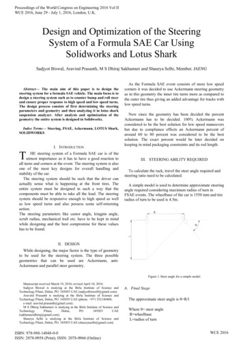
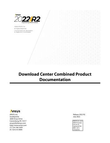
IntroductionThe component parts of the steeringcolumnThe main components of the new power steeringsystem are:- the steering column switch,- the steering column tube,- the worm gear,steering position sender, andsteering moment sender- the electro-mechanical power steering motor,- the steering column electronics control unit,and- the universal joint shaft to the mechanicalsteering gear.Steering column switchSteering column tubeWorm gearSteering columnelectronics control unitElectro-mechanical powersteering motorUniversal joint shaftto mechanical steering gear225 0024
What you need to know about thefunction of the electro-mechanicalpower steering system:1. The system offers the driver power-assistedsteering in dependence on actual drivingconditions225 060225 0612. The steering movement of the driver istransmitted to the worm gear and steeringgear via the steering shaft and an intermediate spindle.3. Self-alignment of the steering wheel inthe straight-ahead position is assisted by theelectro-mechanical power steering system.225 0624. The system conveys the feeling of contact withthe road to the driver.225 0635. The system monitors the input and output signals, as well as operation of the componentparts of the steering system.225 0666. The safety steering column is adjustable forheight, and incorporates the proven crashconcept pioneered in the Lupo.225 0657. It provides anti-theft protection through a lockon the steering shaft.225 0645
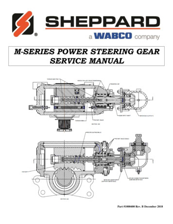
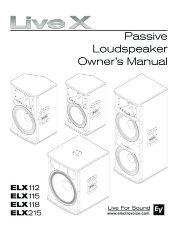
IntroductionOverviewSteering column switch andsteering-wheel lockUniversal joint shaftSteering column tubewith height adjustmentControl unit with sensors,electric motor andworm gearSteering gearThe entire electro-mechanical power steeringsystem is integrated in a compact unit. This unitcomprises all component parts of the steeringgear, e.g. control unit, electric motor and thesensors required for control. Hence, there is nolonger any need for complex wiringarrangements.225 038
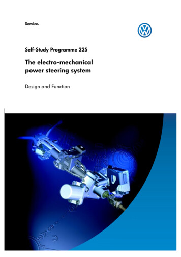
A electro-mechanical power steering system and a hydraulic system have totally different modes ofoperation.By comparison:The specifications emphasise the difference.HydraulicsElectro-mechanical systemWeight16.3 kg11.3 kgPower consumptionUrban cycleMotorway cycle400 W25 W800 - 1000 W10 W0.1l *0.01 **Additional consumption compared to mechanical steeringgear in litres per 100 km* referred to 44 KW SDI engine** referred to Lupo 3L with1.2l TDI engineThe hydraulic power steering systemUniversal joint shaftIn the hydraulic power steering system, the system components after the universal joint shaftare engaged in the steering operation, wherebysteering is assisted by oil pressure.225 040The electro-mechanical power steering systemIn the electro-mechanical power steeringsystem, steering is assisted in front of theuniversal joint shaft. In this system, the assistingmoment is generated by an electric motor.Universal joint shaft225 039
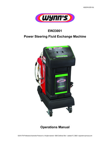
The steering mechanismThe steering column and its component partsThe key component parts of theelectro/mechanical power steering system are:-Steering shaftSteering column tube with height adjustmentIntermediate spindleTorsion barSensor housing with steering moment senderand steering position sender- Electric motorand coupling- Worm drive with wormand gear- Gearbox housing- Steering column electronics control unit and- universal joint shaftSensor housing withElectric motorsteering moment sender andIntermediate spindlesteering position senderCouplingTorsion barWorm drive withSteering shaftworm and gearSteering column tube with heightadjustment225 017Universal joint shaftSteering column electrics control unit
The torsion barAssemblyThe central component part of the electro/mechanical power steering system is thetorsion bar.It is made from tempered steel, which allows thebar to rotate about its longitudinal axis. The torsion bar mechanically connects the intermediatespindle to the worm drive shaft.225 044IntermediatespindleTorsion barWorm drive shaft withgear wheel225 043Ball bearingFunctionMechanicalconnection225 026225 025Twist of the torsion bar at the start of asteering wheel movementThrough this connection, the intermediate spindleand the worm drive shaft are able to counterrotate about a narrow angle. This narrow angleis enough for the system to detect the start of asteering operation.
Steering mechanismThe worm gearis located in an aluminium gearcase where theelectric motor is also mounted.A worm on the motor shaft meshes with the gearon the steering shaft. The gear ratio is 22:1. Thegear body and the worm are made of metal. Thegear ring is manufactured from plastic to reducemechanical noise.225 020Electric motorHousingRubber coupling225 018Worm gear shaftwith gear wheelWorm
The height adjustmentThe height adjustment mechanism is securelyconnected to the steering column tube. Adjustment travel is 39 mm.225 003The universal joint shaftTelescopic arm225 009225 023The two forks of the drive shaft are connected toa short telescopic arm. This telescopic arm allowslength compensation of the height adjustmentmechanism and affords the occupants protectionin a head-on collision.If the steering wheel is adjusted upwards, the telescopic arm is compressed (i.e. made shorter).This reduces the distance between steering wheeland steering gear.225 021225 024225 022If the steering wheel is adjusted downwards,the distance between steering wheel and steering gear is increased, and the telescopic arm isextended.
System overviewSteering column electronicscontrol unitJ527SensorsActuatorsElectro-mechanical powersteering motorV187Steering position senderG268 andsteering moment senderG269Electro/mechanical powersteering warning lampK161in the control unit with displayunit in the dash panel insertJ285Road speed signal from controlunit with display unit in the dashpanel insertJ285225 0413-phase AC alternator,D / terminal 61
The electronics of the steering systemThe sensor housingTorsion barSteering position sender G268 and steeringmoment sender G269 are located in a housing.The sensor housing is mounted on the worm gearshaft above the gear. The sensor housing is connected to the control unit via a 6-pin connector.SenderhousingWorm gear shaft225 010Steering position sender G268is connected to the worm gear shaft. It registersthe steering wheel lock and/or the current position the steering.Steering moment sender G269225 012is connected to the torsion bar. It registers a rotation angle of the torsion bar in relation to theintermediate spindle. The control unit calculatesa torque from this signal. If the calculated torqueexceeds a value of 0.01 Nm, the control unitassumes that a steering assistance is required.225 011
The electronics of the steering systemElectrical circuitG268G269The two sensors are connected to the control unitby three separate wires.Effects of failureIf the steering moment sender fails, the system isdeactivated. If the steering position sender fails,the »active self-alignment« function is deactivated. In both cases, the fault indicator lampcomes on.J527225 046Sensor designInner ringThe two sensors are sliding contact potentiometers. The steering position sender registers thesteer angle of the steering system through rotation of the inner ring in relation to the housinglower section. The steering moment sender registers the rotation of the torsion bar.The housing has an inner ring. This ring ismounted on the worm drive shaft with a clamping ring and can rotate relative to the housing.Two pairs of potentiometers scan the brushes ofthe inner conductor on the PCB in the housing.This part is the steering position sender.The other conductors transfer the signal from thesteering moment sender.Potentiometer brushesHousing lower section225 010Potentiometer conductors225 013Clamping ring
The steering moment sender is mounted in theinner ring. The inner ring is a plastic ring with twopairs of potentiometer brushes. These brushesscan the four conductors in the inner ring.The sender ring is connected to the housingcover. It fits exactly on the head of the torsionbar. When the torsion bar rotates, the cover alsorotates relative to the inner ring. This movement isdetected by the potentiometer brushes and transferred to the control unit as a signal along theprinted conductors in the base of housing.Housing coverPotentiometerbrushesSender ringOpen inner ring225 015225 014Printed conductor
The electronics of the steering systemSteering columnelectronics control unit J527This control unit is mounted in a frame which isbolted to the housing of the worm drive.Five non-interchangeable connectors areattached to the terminal strip of the control unitby clips.225 016The control unit calculates the steering assistancerequired from the data from the sensors, makingallowance for road speed.Effects of failureIf the control unit fails, the fault indicator lampcomes on.225 037UsageConnection to senders G268 and G269Motor control leadsElectric motor phase wiresVoltage supply, battery terminal 30 and earth terminal 31Connection to control unit for display unit in the dash panel insertterminal 15, terminal 61, fault indicator lamp,K-wire, road speed signalDrawing colour
Electro-mechanical power steeringmotor V187This motor is bolted to the housing of the wormgear by means of rubber buffers so that novibrations can be transmitted between the motorand steering column. The motor shaft is connected to the worm shaft via a flexible rubbercoupling in such a way that motor starting torqueis transmitted softly to the worm gear. The motoritself has a maximum power consumption of720 W and develops 2 Nm of torque. It has anextremely short response time which allows it toassist steering wheel movements quickly.225 019J527Electrical circuitThe electric motor receives its voltage supply viasteering column electronics control unit J527.V187225 048Electro-mechanical power steeringwarning lamp K161This warning lamp is located in the dash panelinsert.If the control unit detects a fault in the powersteering system, it activates the warning lamp inthe display unit in the dash panel insert.225 027
Functional descriptionThe steering operationUpper sectionLower sectionControl unitThe diagram shows a steering column whichis split into an upper section and a lower section.The steering moment sender is integrated in theupper section, while the steering position senderis located in the lower section.225 071Torsion bar225 070225 012Steering position senderThe driver starts to turn the steering wheel.The torsion bar is rotated at the same time.The steering moment sender, which rotatestogether with the torsion bar, supplies the controlunit signals indicating the magnitude and direction of rotation of the torque acting on the steering wheel. The control unit calculates the torqueassistance required from the signals and activates the electric motor. The aggregate of torqueacting on the steering wheel and torque assistance is the effective torque acting on the steeringgear.225 011Steering moment sender225 073225 074The torsion bar isrotated from the steering wheel.Torque acting on steering wheelTorque assistanceEffective torque225 081225 086
Electric motorIf the driver increases the torque applied to thesteering wheel, the electric motor increasestorque assistance. This allows the steering gear torotate easily.225 084225 075The torsion bar continues to rotate becausethe driver continuesto apply steering lock225 081If the driver reduces the torque applied to thesteering wheel, the torsion of the torsion bar isreduced. As a result, the steering moment sendersupplies a lower signal to the control unit.The control unit reduces the torque assistance byactivating the electric motor.Due to the wheel alignment, the steering systemtries to restore the wheels to the straight-aheadposition.225 085225 083The torsion of thetorsion baris reduced.225 091If resultant restoring moment via the steeringgear is greater than the aggregate of the torqueacting on the steering wheel and the torqueassistance, the system begins to turn the steeringback to the straight-ahead position.
Functional descriptionActive self-alignmentElectric motorIf the driver releases the steering wheel whencornering, the tension on the torsion bar isrelieved. At the same time, the electronics deactivate the electric motor. As a result, torque assistance is no longer required.225 089225 079225 088225 080If the vehicle is still not travelling straight ahead,this is registered via the steering position sender.The electric motor is now activated so that thesteering is actively turned to the straight-aheadposition.225 076225 078Torque acting on steering wheelTorque assistanceEffective torque225 090225 088
Function diagramKD G268G269K2SK161J285SJ527CV187225 042C3-phase AC alternatorG268 Steering position senderV187 Electro/mechanical power steering motorKDiagnostic connectionG269 Steering moment senderJ258 Control unit for display unit indash panel insertJ527 Steering column electronics control unitK2Alternator warning lampK161 Electro-mechanical power steering warning lampSFuseInput signalOutput signalPositiveEarth
ServiceSelf-diagnosisThe self-diagnosis procedure is initiated withaddress word 44 "Power steering".In the self-diagnosis, the electro/mechanicalpower steering control unit provides the following functions and can be interrogated with Vehicle Diagnostic, Testing and Information SystemVAS 5051:FunctionAddresswordInterrogate control unit version01Interrogate fault memory02Clear fault memory05Read data block08Start basic adjustment04End of output06210 102Servicing the steering systemAt present, only the following components of theelectro/mechanical power steering system maybe replaced individually:The gearbox with steering column tube,the control unit and the electric motor are alwaysreplaced as a whole and may not be disassembled under any circumstances. the steering column switch and the lock cylinderPlease observe the instructions in the Workshop Manual.
Test your knowledge1. What sender is required for operation of the electro/mechanicalpower steering system?a.The steering position sender onlyb.The steering moment sender onlyc.The steering position sender and the steering moment sender2. What is the transmission ratio in the worm gear?a.21:1b.22:1c.23:13. Define the following components225 071225 070Solutions:1.c2. b3. Components: see page 18
225For internal use only VOLKSWAGEN AG, WolfsburgAll rights reserved. Technical specifications subject to change without notice.040.2810.44.20 Technical status: 1/00 This paper is produced fromnon-chlorine-bleached pulp.
Urban cycle Motorway cycle 400 W 25 W 800 - 1000 W 10 W Additional consumption com-pared to mechanical steering gear in litres per 100 km 0.1l * 0.01 ** * referred to 44 KW SDI engine **referred to Lupo 3L with 1.2l TDI engine The electro-mechanical power steering system In the hydraulic power steering system, the sys-