Transcription
M-SERIES POWER STEERING GEARSERVICE MANUALPart #1000400 Rev. B December 2018
NOTES2
TABLE OF CONTENTSSECTIONPAGESafety NoticeIntroduction45Steering Gear IdentificationCutaway Picture of M-Series Power Steering GearGlossary of TermsSteering Gear Operating PrinciplesOil Flow through the Steering GearDual Steering Gear SystemsStandard Slave SystemCooling Slave SystemSpecifications689111314151617Pre-Delivery Inspection for Sheppard Steering SystemsPreventive MaintenanceSeal Kits and Acceptable Fluids181920Diagnosis and TroubleshootingProblem Diagnosis GuideTroubleshooting Procedure212228Steering Gear Replacement and AdjustmentPitman Arm Removal and InstallationAxle Stop AdjustmentRelief PlungersBleeding Air from Steering GearsTool Order Form343537384042Expanded View Drawings of Steering GearsInput Shaft Seal ReplacementSector Shaft Seal ReplacementEnd Cap Seal ReplacementRelief Plunger Repair4344464951Pressure Relief Valve (PRV)Miter BoxesTorque Specs, Socket Sizes and Tools required for repairsTroubleshooting Checklist545556573
SAFETY NOTICEBefore you begin any maintenance, troubleshooting or repairs, please read this manual carefully.The procedures outlined in this manual have been assembled to provide service technicians the bestpossible information available on troubleshooting and repairing Sheppard M-Series Steering Gears atthe time of this publication. Sheppard D-Series and 92-Series Steering Gears are covered in separateservice manuals. To ensure safe and reliable operation, the service and repair procedures must befollowed carefully. This manual has been written using the ANSI Z535.6-2011 Standard as a guide.THIS MANUAL CONTAINS SAFETY ALERT SYMBOLSAND SIGNAL WORDS TOIDENTIFY PERSONAL INJURY OR PROPERTY DAMAGE. BE ALERT TOAND- THE INFORMATION FOLLOWING A SAFETYSIGNAL WORD OR SAFETY ALERT SYMBOL WILL SAVE YOU FROM INJURY ORUNNECESSARY REPAIR.This Safety Alert Symbol is used to alert you to potential physical injury hazards. Obey all safetymessages that follow this symbol to avaoid possible injury or death.Indicates a hazardous situation that, if not avoided, WILL result in death or serious injury.Indicates a hazardous situation that, if not avoided, COULD result in death or seriousinjury.Indicates a hazardous situation that, if not awoided, could result in minor or moderateinjury.Indicates information considered important, but not hazard related. It identifies possibleproperty damage.SECURE FOR SERVICEThe term "Secure for Service" is used throughout this manual to identify when the vehicle should be putin a condition where maintenance can be performed safely, with minimal risk of personal injury orproperty damage. Local shop safety practices apply and may include, but are not limited to: Wear Personal Protective Equipment (PPE) such as eye protection and chemical resistant gloves Set the Parking Brake Chock the wheels Remove the ignition key Disconnect the battery Have the means to properly contain and dispose of fluidsIf at any time you have questions or comments, contactthe Sheppard Field Service Hotline at 800-274-7437.4
INTRODUCTIONThis service manual covers only repairs to Sheppard M-Series steering gears. The vehicle manufacturer's service manualshould be used for removal and installation instructions of the steering gear, power steering pump, and all other steeringsystem components.All information, pictures, illustrations and specifications in this manual are the latest available at the time of printing. Wereserve the right to make changes without notice. If you are not certain you have the current revision of this manual, or if youhave questions about any procedures, please call our Field Service Hotline at 800-274-7437 before you begin repairs.The R. H. Sheppard Company was founded in 1937 by Mr. R. H. Sheppard when he purchased a one storyfactory on East Middle Street in Hanover, PA. The rights to produce the existing product lines of theKintzing wire cloth loom, floor polisher and gas engine generator were also purchased. These productsprovided the basis of the manufacturing facility and a place where the diesel engines could be developed.As various uses were found for the diesel engines and business prospered, the other lines were phasedout.From that one story factory on Middle Street, the company purchased the factory on Philadelphia Street in1940 and the foundry in 1943. These plants were expanded over the years to their present sizes. In 1981,construction began on the first bay of Plant 5, which has been expanded to include three bays, totaling52,000 square feet. The Technical Center was completed in 1988 to provide full function testing of all ofour products and to help in the solving of our customers' engineering problems. With the completion ofthe new foundry in 1990, our foundry capacity was doubled. The latest addition to the company has beenthe facility in Wytheville, VA, which covers 64,000 square feet. This facility provides support for theHanover manufacturing facility, as well as producing the sway bar product linefor Kenworth. The first diesels were produced experimentally as early as1933, after Mr. Sheppard graduated from Dickinson College. In all, twentybasic models of engines were developed and marketed throughout the world.These engines were used to power generator-sets, pumps, life boats, rescuecraft, refrigerated railroad cars, and farm tractors. The diesel engines werethe first love of Mr. Sheppard, and he searched for a long-term use for thirtyyears. The engines were produced fromthe 1930's to 1963.The first power steering gear wasapplied to the SD-4 tractor in 1953, andsoon would find its way to heavy dutytrucks. In the years between the end oftractor production and the totalcommitment to power steering in 1963,the company produced one of the first ice vending machines thatwould store bags of ice and automatically dispense them as a sodamachine does today. Although the ice machine was never asignificant product for the company, it should be mentioned.In 1963, R. H. Sheppard totally committed the company'smanufacturing and engineering resources to the production of power steering. Over the years, thecompany has been issued more than two dozen patents on steering, from both R. H. and Peter Sheppard.This continued commitment - to produce the highest quality steering components possible - led to theintroduction of the M-series family of gears in 1986. The M-series includes five basic models, with severalhundred variations of those models in our system.Our products are used throughout the U.S. and Canada, as well as ten foreign countries around the world.Whether the product is power steering for the transportation industry, econovances for cleaner, moreefficient engines, sway bars for suspensions or certified castings - our focus and our success has been toprovide the highest quality products and the best service possible.5
STEERING GEAR IDENTIFICATIONBASIC MODEL NUMBERThe basic model number is cast into the center of the main housing, and identifiesthe basic family the steering gear belongs to. Examples are: M80 M83 M90 M100 M110STEERING GEAR MODEL AND SERIAL NUMBERLetters and numbers are stamped or pin-printed into the housing at the edge of thesector shaft bore, to identify the steering gear sub-model and serial number. Whenthese numbers are combined with the basic model number (cast into the housing),they give you the complete steering gear model and serial number. Examples are: SAW1 10A03034(M80SAW1) PAM22 07B05553(M83PAM22) SAD17 04G05490(M90SAD17) PMX3 R09L0332(M100PMX3R) PJZ34 09E07748(M110PJZ34)PITMAN ARM AND COLUMNREMOVEDNOTE: No matter how the steering gear is mounted to the chassis, the model andserial number will be stamped into the housing on the side which is visible.AUTOThe word AUTO cast into the housing next to the basic model number means thesteering gear has Automatic Relief Plungers. If AUTO is not present the steeringgear has Manual Relief Plungers. See the appropriate section of this manual on howto set the relief plungers.BASIC MODEL NUMBER (M100)(INVERTED)WHAT IT ALL MEANSExample: M100PMX3R M-Represents the Series of the steering gear, the M-Series. Other Seriesare D-Series and 92-Series. 100-Indicates the diameter of the piston in millimeters. There are also 80,83, 90 and 110. The larger the piston the more powerful the steering gear. P-Stands for Power or Primary steering gear. It will be the one connectedto the steering wheel and be the Master gear for multiple steering gearsystems. S in this position means Slave or Secondary steering gear onheavy or multiple axle chassis. It will not be connected to the steeringwheel and receives its pressure from the Primary or Master steering gear. MX-Is the next set of letters in sequence assigned when this particularmodel was created. It also means this steering gear is designed for aspecific application, as are all Sheppard steering gears. An MX is notinterchangeable with an SS, MT, QS, DQ. Contact your vehicle dealer orSheppard Field Service for questions on steering gear applications. 3-Indicates the steering gear has Automatic Relief Plungers. Otherdesignators are: 1-Indicates Manual Relief Plungers, 2-Indicates a special application, two digits mean the steering gear camefrom Sheppard with a Pitman Arm attached. R-Shows the steering gear was remanufactured by Sheppard.“A” with a number-Indicates the steering gear was built with a specialmounting bracket (M110PBT1A2).6REMOVE PAINTPMX3
THE SERIAL NUMBERExample: R08C1672 R-Shows the steering gear was remanufactured by Sheppard. 08-Year the steering gear was built. C-Month of the year the steering gear was built (March 2008). 1672-Sequential serial number for gears built that month.If you ever need assistance with a steering problem, it is important you have thecomplete model number and serial number.703D09920
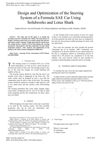
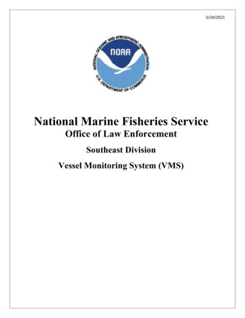
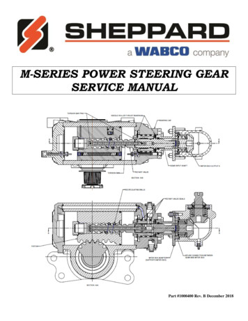
CYLINDER HEADAUTOMATICRELIEF PLUNGERSRELIEF BALLSand SEATSRECIRCULATINGBALL THREADROTARY VALVETORSION BARPISTONINPUT SHAFTCYLINDERPISTONRACK TEETHINPUTSHAFT SEALSECTORSHAFT SEALBEARING CAPCOVERHOUSINGBEARING CAPPITMAN ARMRETAINERSECTORSHAFTSECTORSHAFT COVERM-SERIES POWER STEERING GEAR8
GLOSSARYOF .Back-Driving Slave Gear – Used to steer additional axel(s). Receives hydraulic assist pressure from a master gear. The pitmanarm is linked to the master gear and the input shaft is driven by the piston. The input shaft is connected to and used to actuate anadditional steering gear on another axle.Back Pressure – Circulating pressure of the steering system when the steering wheel is not being turned.Ball Return Retainer Plug – Plug in the side of the piston that holds the recirculating balls and ball guides in place inside thepiston. NOT SERVICABLEBase Mounted Gear – The steering gear is mounted to the frame or bracket using the mounting holes in the housing opposite thesector shaft cover.Bearing Cap – End cap that contains the input shaft and rotary valve.Bearing Cap Cover – Small round cover with 4 small bolts and a hole for access to a relief plunger, on the end of the bearingcap. It contains the input seal, salt seal, and on newer models the retaining washer.Bleeder Screw – 1/8” Allen set screw located in a ¾” plug on the top of the housing (if the steering gear is mounted with thesector bore up, or directly in the end cap of some slave gears.Cylinder Bore – Long part of housing which contains the piston.Cylinder Head – End cap on the housing which does not have the input shaft. It contains a relief plunger, but not on slavesteering gears.Crab Bracket – The metal bracket mounted to the bearing cap on some vehicles which holds a bearing the steering columnpasses through.Draglink – The connection between the pitman arm on the steering gear and the steer arm on the wheel hub.Flow – The movement of fluid or the speed it is moving. Expressed in Gallons Per Minute (GPM).Housing – The main body of the steering gear which all parts bolt to or are held by.Intermediate Shaft – The section of the steering column which extends between the cab and the steering gear, normally 2sections with one sliding inside the other.Input Shaft – Shaft the steering column universal joint connects to. Part of the control valve which directs fluid to either end ofthe piston.Miter – An independent or attached gear set which changes the direction of the steering column to the input shaft of the steeringgear. NOT SERVICABLE.Miter T Box - An independent or attached gear set which changes the direction of two steering columns to the input shaft of thesteering gear. NOT SERVICABLE.Mounting Bracket – A metal piece which allows the steering gear to be adapted to the frame of a vehicle.Mounting Feet – The legs or pads cast into the housing which allows the steering gear to be mounted to a vehicle by means ofnuts and bolts.Piston – Located in the cylinder bore of the housing. Redirects mechanical and hydraulic input force to mechanical output forcethat moves the sector shaft and pitman arm. NOT SERVICABLE.Piston Ring – Teflon seal ring around most (not all) pistons. NOT SERVICABLE.Pitman Arm – The lever which mounts on the splined end of the sector shaft and connects to the draglink.Pressure – Hydraulic force created by the pump used to help move the piston in the steering gear. Measured in Pounds perSquare Inch (PSI).Pressure Relief Valve (PRV) – Used on some (not all) steering gears when the pump maximum pressure is higher than what thesteering gear is designed to operate at. Housed in the bearing cap and identified by a large 1 ¼” nut on the bearing cap.Pump – The device which supplies fluid under pressure to the steering gear.Rack Teeth – The area on the piston which engages the sector shaft teeth.Recirculating Balls – 24 steel balls used as bearings which provide the connection between the rotary valve and piston.Recirculating Ball Thread – The area on the rotary valve and inside the piston where 24 steel recirculating balls travel.Relief Check Ball and Seat – Located in each end of the piston and held in place by a long spring between the two balls. Used torelieve system pressure when dislodged by the relief plunger at the end of steering travel.Relief Plunger – A long pin located in each end cap of the steering gear (not on slave gears). It may be mechanical or automaticand should be adjusted to relieve hydraulic assist pressure before the axle stop contacts the axle.Rotary Valve – Internal valve located in the bearing cap of the steering gear which directs fluid to either end of the piston. It isactuated by turning the input shaft by the steering wheel, through the steering column and universal connection.Sector Shaft – The output shaft of the steering gear which is the connection between the piston and pitman arm.Sector Shaft Seals – 2 piece pressure seals located between the bearing and outside of the housing on each end of the sectorshaft. One is in the housing and one is in the sector cover.Sector Bore – Area of the housing which contains the sector shaft.Sector Cover – Steel cover which houses a bearing and sector shaft seal. It may be solid and cover the end of the sector shaft, orthe shaft may pass through the center of it (depending on the steering gear design). May be held in place by bolts, or a large snapring, or by 3 clips retained by two bolts in each clip.9
36. Slave Gear – A steering gear not directly connected to the steering wheel used to assist a master (or primary) steering gear. It ispowered by hydraulic pressure sent from the master gear.37. Slave Ports – Threaded openings which may be found in the cylinder head, bearing cap, or sector bore used for the hose fittingswhich connect the pressure lines to the slave gear(s).38. Steer Arm – Arm on the wheel hub the draglink connects to.39. Steer Axle – Any axle that controls the direction of the vehicle when the steering wheel is turned.40. Steering Column – The linkage assembly which connects the steering wheel to the steering gear input.41. Steering Gear – Mechanical/hydraulic device used to convert the rotary motion of the steering wheel into a linear motion for thepitman arm.42. Steering Wheel – The round object the driver turns with his hands to guide the vehicle left and right.43. Tab-Lock Retainer – Allen head bolt assembly used to provide the initial torque for installing the pitman arm. Uses alignmenttabs that fit into the pitman arm and retraining tabs which fold into the bolt head and prevent it from backing off after beingtorqued.44. Thrust Bearing – Needle roller bearings on both ends of the rotary valve in the bearing cap.45. Thrust Bearing Shim – Shims located next to the thrust bearings in the bearing cap which provide a smooth hardened steelsurface for the bearings to ride against.46. Thrust Washer – Washer on end of the rotary valve which determines valve end play in the bearing cap.47. Torsion Bar – Bar which connects the input shaft to the rotary valve and returns the valve to a neutral position.48. Universal Joint – The part of the steering column which allows the sections to connect at different angles.49. Valve Seals – 3 grooved seals on the outside of the rotary valve each with a rubber energizing ring. NOT SERVICABLE.10
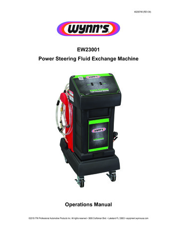
STEERING GEAR OPERATING PRINCIPLES1.The INPUT SHAFT is connected to the steering column universal joint, and iscentered within the ROTARY VALVE in the neutral position by the TORSIONBAR. It is an open centered valve which allows fluid to flow directly through thesteering gear and back to the reservoir at low pressure when the engine is runningand no force is applied to the input shaft. The ROTARY VALVE is supportedboth top and bottom in the BEARING CAP by a series of THRUST BEARINGS,SHIMS, and a THRUST WASHER which are constantly bathed in steering fluid.2. The INPUT SHAFT HIGH PRESSURE SEAL and SALT SEAL are located inthe BEARING CAP COVER. No greasing of the seals is required. A FACESEAL (dust boot) is installed over the INPUT SHAFT as extra protection for theseals.3. The ROTARY VALVE SHAFT BALL THREAD rotates within the piston on 24STEEL RECIRCULATING BALLS.4. The SECTOR SHAFT rotates on two ROLLER BEARINGS which are constantlylubricated by the steering fluid. The SECTOR SHAFT PRESSURE SEALS arelocated next to each bearing.5. The SECTOR SHAFT TEETH engage the PISTON RACK TEETH machinedinto one side of the PISTON. The PITMAN ARM is mounted on the taperedsplines of the SECTOR SHAFT. The arm will get tighter on the splines the harderit is worked. The PITMAN ARM RETAINER applies the initial pressure to thearm to seat it onto the shaft, and then acts as a safety device to prevent the armfrom coming loose if it was not properly torqued.6. RELIEF PLUNGERS are located in both the BEARING CAP and CYLINDERHEAD and may be either manual or automatic depending on the steering gearmodel. They must be correctly adjusted to obtain full turn angle (wheel cut) of thesteering and still prevent the axle stops from hitting the axle under full steeringpump pressure.7. Turning the steering wheel turns the steering column and rotates the INPUTSHAFT. This overcomes the resistance of the TORSION BAR which opens theROTARY VALVE to allow as much pressure as is needed from the pump to pushthe PISTON through the CYLINDER BORE. (The more resistance encounteredin trying to steer the wheels, the more the valve opens and more pressure from thepump is applied to the piston.)8. At the same time, the ROTARY VALVE opens a passage back to the reservoirfor the fluid in the opposite side cylinder cavity, allowing it to drain, and closesoff the flow of fluid from the pump going directly to the reservoir.9. Fluid pressure and flow will push the pressure side RELIEF BALL off its BALLSEAT, and along with the RELIEF SPRING pressure, force the opposite sideRELIEF BALL onto its BALL SEAT (sealing off any internal leakage throughthe piston).10. When the wheels are steered to the full turn angle the PISTON will move throughthe CYLINDER BORE until the RELIEF PLUNGER contacts the RELIEF BALLand pushes it off its seat, opening the flow path for fluid back to the reservoir anddumping steering system pressure. This ensures there is not enough power assistto keep turning and drive the axle stop into the axle. The process reverses forsteering the opposite direction.ROTARY VALVE ASSEMBLYBEARING CAP COVERINTERNAL COMPONENTSINPUT AND ROTARY VALVEASSEMBLYWhen the engine is running, there is a constant flow of oil at low pressure through thesteering gear until a force is applied to the steering wheel. This constant oil flowprovides instant steering response and absorbs road shocks for smooth operation.NOTE: If there is a loss of power steering pump pressure while driving, the steeringgear is designed to provide a mechanical back-up so the vehicle may be safely steeredto the side of the road.Steering gears may be built with an integral PRESSURE RELIEF VALVE if thepower steering pump has no relief, or the pump delivers higher pressure than the gear11END OF TRAVEL RELIEF
is rated. This valve protects the steering gear against excessive pressure and reducessystem temperature by avoiding high pressure by-pass and recirculation within thepump.Sheppard steering gears are designed to provide long service life and simple repair.The sector shaft to piston rack never requires center point adjustment. The reliefplungers, once set initially, do not require adjustment unless axle stop settings or tiresize is changed. With routine care and limited maintenance, Sheppard M-SeriesSteering Gears will provide many miles of reliable performance.PRESSURE RELIEF VALVE(PRV)12
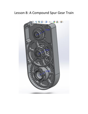
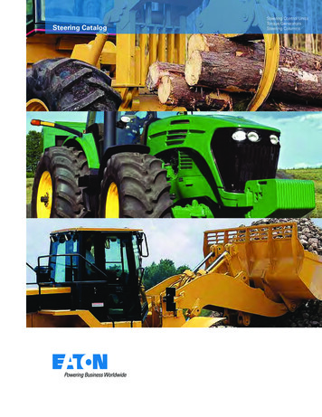
OIL FLOW THROUGH THE STEERING GEARHere the steering gear is in the neutralposition with no force being applied tothe steering wheel in either direction.There is equal-low pressure at bothends of the piston and fluid is flowingthrough the bearing cap and right backto the reservoir. This provides ahydraulic cushion to help damper roadshocks, and an instant reaction whenhydraulic force is needed to help movethe piston under load.In this example, when the steeringwheel is turned to the left, the rotaryvalve opens allowing fluid topressurize the bearing cap end of thepiston, and the sector shaft bore. Atthe same time, the valve is closing offthe return to the reservoir. The moreforce required to turn the steering, themore the valve directs fluid to thepiston instead of the reservoir. Whenmaximum force is needed to turn thesteering, all pump output is directedby the valve to the piston and noneescapes to the reservoir.Turning the steering wheel to the rightdirects fluid to the cylinder head endof the piston. It also begins closing offthe flow back to the reservoir, andallows the bearing cap end to drain tothe reservoir.13
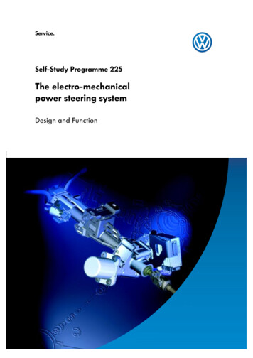
DUAL STEERING GEAR SYSTEMSTwo or more steering gears are sometimes used where steer axle weights exceed 16,000 lbs gross axle weight rating. Multiple gears,or gears and hydraulic assist cylinders, are used to balance the steering forces across the axle(s) and save space, instead of using amassive single steering gear.Slave (secondary) steering gears are driven or operated by hydraulic pressure sent from the master (primary) steering gear connectedto the steering wheel. The pressure pushes the slave gear piston (or cylinder piston) to provide power assistance. As the steering wheelis turned, the valve opens in the master gear allowing pump pressure to build on one side of the master gear piston, which alsopressurizes the line going to one side of the slave gear piston. When the steering wheel is let go, the valve returns to center and closesoff the pressure going to the gears.Relief plungers are only installed in master steering gears, and will relieve system pressure for the entire system at the end of steeringtravel. Power steering pumps must be sized appropriately to provide enough flow for the additional gears, but not so much that itcauses excessive backpressure on the master gear control valve. Normally, the gears are all mechanically linked together through thepitman arms, axle steer arms, tie rods, and draglinks to obtain correct consistent steer angles.IMPORTANT: A special procedure (found in this manual) is used to bleed dual systems. It is critical this procedure befollowed if the system has been repaired or serviced.M-Series Cooling Slave - A 4 line slave gear having a high pressure line on each end of the steering gear and has a port cast into thelength of the housing. Fluid returning to the reservoir from the master gear is routed through this port to use the slave gear as a heat sinkto reduce steering system temperatures. This line is low pressure and completely separated from the high pressure ends of the gear.M80SAW1 (COOLING SLAVE)M-Series Standard Slave - A 2 line slave gear which has a high pressure line on each end of the steering gear and no return lines.M90SAD1 (STANDARD SLAVE)D-Series Slave - A 2 line slave gear that has a high pressure line connected to the cylinder head, and one to the sector shaft bore of thehousing. This configuration eliminates the need for bleeding air from the sector bore. No return lines are attached.HD94SG1 (D-SERIES SLAVE)92-Series Slave - A 4 line slave gear having a high pressure line on each end of the steering gear and has the fluid returning to thereservoir from the master gear routed through the sector shaft bore to use the slave gear as a heat sink to reduce steering systemtemperatures. This line is low pressure and completely separated from the high pressure ends of the gear.292SEZ6 (92-SERIES SLAVE)14
STANDARD SLAVE SYSTEM15
COOLING SLAVE SYSTEM16
SPECIFICATIONSEach vehicle manufacturer specifies the maximum system operating pressure and pump flow for their various steering installations.Some pumps may have to provide fluid to accessories such as fan drives, fifth wheel lifts, hydraulic booms, or PTOs. Always consultthe vehicle manufacturer's specifications for the correct pump relief pressure and flow for the vehicle you are working on.DO NOT INCREASE THE MAXIMUM SYSTEM PRESSURE WITHOUT CONSULTING THEVEHICLE MANUFACTURER. SERIOUS PERSONAL INJURY OR EQUIPMENT DAMAGE MAY RESULT!Before any steering gear or pump is replaced for poor performance, consult the DIAGNOSIS AND TROUBLESHOOTING sectionof this manual and complete the TROUBLESHOOTING CHECKLIST. Many times gears and pumps are replaced needlessly due tomisdiagnosis of a problem. Steering gears returned under warranty which are tested and found to have no defects will not bereimbursed. If you have any questions about your troubleshooting diagnosis, contact your vehicle manufacturer's tech line, or theSheppard Field Service Hotline at 1-800-274-7437.17
PRE-DELIVERY INSPECTION (PDI)FOR SHEPPARD STEERING SYSTEMSTHESE ARE ONLY GUIDELINES PROVIDED BY SHEPPARD. THEY ARE NOT INTENDED TO REPLACE THEDIRECTIVES OF THE VEHICLE MANUFACTURER AND ARE NOT REIMBURSEABLE BY SHEPPARD.1.2.3.4.5.Ensure the vehicle is at normal operating temperature.NOTE: It is important to follow the steps of this inspection in sequence!Start the engine and check the fluid level in the power steering reservoir. It should bebetween the minimum and maximum markings. If fluid is needed, refer to the vehiclemanufacturer's guidelines on what fluid is to be used.Inspect the system for any fluid leaks. Ensure all hose fittings and clamps are tight.Inspect the hose routing for any kinks in the hose, or clamps that are too tight and crushthe hose. Any restriction must be corrected. Ensure no lines contact any moving parts ofthe engine or chassis. Shut the engine off.Raise the steer tires just off the ground and inspect the steering column, draglink, and allsteering links. Ensure they have been properly greased and all boots are in place.INSPECT THE LINES FOR KINKSEnsure all cotter pins are in place for the castle nuts.6.Make sure the pinch bolt is in place and tight on the universaljoint connecting the steering column to the steering gear input shaft.7.Ensure 2 tabs are bent over and locking the pitman arm retaineron the steering gear.Ensure the rubber sector shaft cover is securely attached. The unpainted end of thesector shaft should not be exposed, if it is exposed, a new cover can be found in theSector Shaft Seal Kit for the model gear you have.Turn the steering full left and full right. (This will set automatic relief plungers in thesteering gear if it has AUTO plungers.)8.9.10.11.12.13.14.MAKE SURE THE AXLE STOPS CONTACT THE AXLEIN BOTH DIRECTIONS! If they do not, there is a mechanical problem; the pitmanarm may be mistimed, steering gear may not be centered, draglink/other steer link maybe adjusted wrong, or the wrong part number could be installed. There could also beinterference on the chassis stopping the movement of the steering.Ensure the axle stops are set per the vehicle manufacturer's specifications. They shouldbe set either to a specific degree of steering travel, or to a minimum clearance at the tireand pitman arm.Set the steer tires on the ground and start the engine. Turn the steering full left and fullright with normal steering effort-do not pull hard on the steering wheel. There should bea small gap between the axle stop and the axle. The axle stop should not hit the axle andmake the power steering pump go into relief. You should hear the steering gear relievepressure in both directions just before the axle stops contact the axle.If there is a large gap between the axle stops and the axle: the relief plungers in the endof the steering gear are relieving too early. Adjust the plungers by backing them out witha screwdriver. If they will not adjust contact Sheppard Field Service at 1-800-2747437.If there is no gap between the axle stops and the axle and the pump is going into reliefbut the steering gear is not: the relief plungers in the end of the steering gear are notrelieving. Adjust the plungers b
5 INTRODUCTION This service manual covers only repairs to Sheppard M -Series steering gears. The vehicle manufacturer's service manual should be used for removal and installation instructions of the steering gear, power steering pump, and all other steering