Transcription
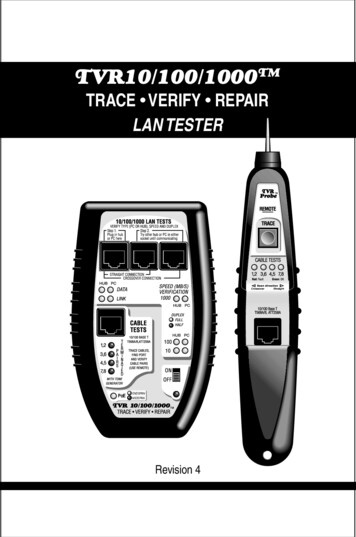
TVR10/100/1000TMTRACE VERIFY REPAIRLAN TESTER PoE ENDSPANMIDSPANRevision 4
Limited WarrantyThe manufacturer warrants to the original consumer that this product isin good working order for a period of one year from the date of purchase.During this period the product will be repaired or replaced without chargefor either parts or labor. Repair or replacement as provided under thiswarranty is the exclusive remedy of the purchaser.CAUTION: The three network jacks are designed to test and withstand PoE voltage, the Cable Tests jack is not. Please take care notto plug the cable test jack into a PoE source. Damage may result.Made in the USA. Copyright 2011.TVR10/100/1000, TVR1000 , TVR and Test, Verify and Repair aretrademarks of Byte Brothers, Inc.Model TVR10/100/1000 User's Guide Revision 4Free DVDThe TVR1000's big brother, the Real World Certifier, has a DVD describing its use. The DVD includes a clip of the TVR1000 in action. Ifyou would like a copy of this DVD, please call 800.999.2983 or emailcs@bytebrothers.com.
Table of ContentsSection I. Introduction .The 10 Most Common Questions answeredTVR10/100/1000 List of functionsSection II. The Three phases of LAN installation .Section III. Faceplate description .Section IV Learning the Main Unit's Faceplate .10/100/1000 LAN Test jacks and LEDsSingle port testingInline testingCable Test Jack and LEDs / Remote ProbeSection V. Learning the Remote Probe's Faceplate .Section VI. Performing LAN Tests .Test example #1. Testing a PC/hub/switch to verify thedevice type, speed, duplex (single port test) and PoE.Test example #2. Cabling a PC to a switch (Inline test).Test example #3. Testing a switch or PC at the farend of a cable for activity (using the Main Unit’s10/100/1000 LAN tests section).Test example #4. Testing a switch or PC at the farend of a cable for continuity (using the Main Unit’sCable Tests section).Test example #5. Tracing a cable's location ("toning")to a wiring closet (or to a switch port).Test example #6. Testing a cable’s pair configuration.Appendix A. Wiring primer .Appendix B. 10, 100 and 1000 Base-T Basics .Appendix C. Ways to Minimize LAN Problems .Appendix D. Self-test and battery replacement .26810172033394344
Section I. Introduction.Negotiation makes networks work. Twisted pair cable is thestandard for local area networks (LANs). Its popularity stems from itsease of use, cost, speed and maybe, most importantly, adaptability.A 10 Base-T device, installed years ago, communicates with a newgigabit switch (1000 Base-T) because the standard that defines Ethernet LANs requires negotiation to a common speed and duplex. Forinstance, a 100 Base-T, half duplex PC connected to a 1000 Base-T,full duplex switch forces the switch to negotiate "down" to 100 BaseT, half duplex mode. Verify this by connecting the TVR1000 "inline"between the two devices and display the negotiated result. Thisinline capability is remarkable and only available on other testersthat cost over 7 times the price of the TVR1000. The TVR1000 alsotests single LAN ports; cables; tones cables; and detects Power overEthernet (PoE). But the inline test is one of its most popular.The 10 most common LAN install and repair questions answered.The TVR1000 is a quick and uncomplicated LAN verification and troubleshooting tool developed by people with expertise in the installation andrepair of LANs. Although they owned TDRs and other high priced testers,they desired an easy-to-use, low-cost tester pair that would quicklyhandle everyday installation and repair tasks common with twisted pairLANs. The result is a tester that quickly answers the 10 most commonquestions that occur during LAN installation and repair.LAN devices questions answered.Is the hub/switch/PC ON and transmitting? See example 1.What speed did 2 devices negotiate? Inline mode. See example 2.Is the speed 10,100,1000MB/s, half or full duplex? See example 1.Is Power over Ethernet (PoE) on the cable? See example 1.Is the hub/switch/PC reducing my LAN speed? See example 2.Does the hub/switch/PC appear as such? See example 1.2
LAN cabling questions answered.Is a hub/switch/PC connected to my cable? See example 4.Does my hub/switch/PC require 2 or 4 pair cable. See example 4.What pairs are terminated in my cable? See example 6.Where is my cable in the wiring closet? See example 5.What hub/switch port is my PC using? See example 5.Is my cabling straight thru or crossover? See example 6.Does a cable have inverted pairs or other faults? See example 6.The TVR1000 is comprised of two units: The “Main unit” and the“Remote Probe.” The Main unit performs the bulk of the tests such asdetermining the LAN device type (is it a hub or PC?); the LAN speed(10,100,1000 MB/s); duplex (full, half); and PoE detection without theneed of the Remote Probe. The Remote Probe adds the ability to tracecable locations (by audibly tracing tones placed on the cable by the MainUnit) and to test the wiring of the cable (by decoding and displayingwiring information placed on the cable by the Main Unit).Broad capabilities: TVR1000 helps you locate faulty hubs, switches,PCs , cables and cable connections that are stopping or limiting theperformance of your LAN. And, if you install devices that require PoE,it detects whether it is available. These capabilities make the TVR1000useful whether you install or maintain LANs and LAN devices.Designed specifically for 10, 100 and 1000 Base-T LANs: TheTVR1000 tests devices and cabling designed to the 10, 100 and 1000Base-T standard. This includes wiring paired to EIA(TIA)568B (alsocalled AT&T258A or simply “AT&T”) and EIA(TIA)568A. EIA(TIA)568Bis the most popular scheme for Base-T cabling. EIA(TIA)568A is themost popular scheme for ISDN cabling. USOC pairing (typically usedfor telephones) is not compatible with the 10, 100 or 1000 Base-Tstandard and is therefore not tested by the TVR1000.3
Multiple test sets in one tester: To accomplish its goals, theTVR1000 performs tests that, prior to the TVR1000, required 8 different test sets. Plus, the multi-functionality is integrated to providea combination of quick results that are not available in any othertester. If the TVR1000 is divided by function, it yields a: Hub/switch/PC verifier that indicates the equipmentDevice Type (is it a hub/switch or PC?). LAN speedometer that verifies the speed (10, 100, 1000MB/s) and duplex of the link (full, half). LAN voltmeter that detects Power over Ethernet (PoE) andindicates whether it is end span or mid span. Straight thru/crossover cable simulator that indicatesthe type of patch cable required. On-line network activity monitor (inline mode) that indicateswhen data is being transmitted (and at what speed,duplex, etc). Tone probe and tone generator for tracing cable locations(and the port used) Cable pairs tester that verifies what cable pairs are wired andidentifies straight thru and crossover configurations. Cable termination tester: Tests for the existence of a LANdevice connected at the end of the cable (determines number ofcable pairs required by the device).It is not only the individual functions of the TVR1000 that makes itso useful. but the creative combination of features that yield anefficient tester that saves time and gets the LAN working quickly.About the manual: The manual presumes that you have a basicunderstanding of Base-T LAN terms such as “hub”, "switch", “PC”and "PoE" and are aware that every connection to a LAN devicerequires the use of a “straight thru” or “crossover" cable. It does notexpect you to be a LAN expert.4
TVR10/100/1000 ("TVR1000") List of FunctionsThe TVR1000 performs the following functions:10/100/1000 BASE-T LAN Tests: The TVR1000 plugs into activehubs, switches and PCs to verify 10, 100 and 1000 Base-T operation.Only the Main Unit is required for these tests. Verifies if a LAN device (hub, switch, PC) is ON, its speeds andduplex capability and if it is wired as a hub, switch or PC. Verifies the negotiated speed and duplex between any twoLAN devices (Inline mode). Detects the presence of Power over Ethernet (PoE) and indicateswhether it is endspan or midspan. Checks if straight thru or crossover patch cable is required. Finds speed bottlenecks on 10, 100 and 1000 Base-T LANs. On-line monitors LAN link (between two devices). Inline mode.Cable Testing and toning: The following tests are performed by theTVR1000 Main Unit and Remote Probe (except where indicated). Locates miswired cables. Locates missing cables. Locates cables that can not support 100Base-T4 and 1000Base-T operation (for LANs that require 4 pair wiring).* Tests connection to hub (pairs connected to hub).* Tests connection to PC (pairs connected to hub).* Tests installed cables (pairs wired and type). Tests patch cables (pairs wired and type). Remote Probe helps locate and trace inactive cables. Remote Probe traces active cables connected to hubsand PC without interfering with LAN performance.* Test performed by the Main Unit only (does not require theuse of the Remote Probe).5
Section II. The Three Phases of LAN InstallationFor LAN installers and repair personnel. The TVR1000 is designedfor both the LAN installer and the LAN repair person. The tests usedduring the three phases of LAN installation can just as well be usedto repair LANs that are suffering operational problems.The installation of a LAN is handled in phases. The cabling isinstalled; then the switches and PCs are installed; and then devicessuch as IP phones and IP cameras. The TVR1000 plays a role duringall three phases, saving countless hours of troubleshooting. Specificexamples for using the TVR1000 can be found in section VI.Phase I. Using the TVR1000 during cable installation. After theLAN cable has been pulled through the building and terminated, itis good practice to verify that the cabling is terminated properly. It isalso a good time to document where each PC cable is located at thehub/switch (before plugging cabling into a new hub, switch or PC). Todo this, use the TVR1000 Main Unit’s Cable Test jack and the RemoteProbe to trace the location of each cable (using the Main Unit’s tonegenerator and Remote Probe’s trace capability). Once a cable endis located, label it. Now, without unplugging the cable from the MainUnit, plug the newly located cable end into the Remote Probe’s RJ45jack. The Remote Probe LEDs indicate the number of cable pairs (andwhether they are straight thru or crossover). Single Step operation:The Remote Probe’s combination of cable tracing and cable pairstesting makes cable locating and verification a single step operation.See section VI, test example 6, for additional information.Phase II. Using the TVR1000 after the hubs, switches and PCs areinstalled. Before connecting the cables to LAN devices, verify that eachhub and switch port and PC are operational. To do this: Connect6
the Main Unit’s 10/100/1000 LAN Test jack (green bordered jack)directly into the device (use the supplied straight thru patch cable) andverify the equipment’s Device Type (i.e. is it a hub/switch or PC?); itsmaximum speed (10,100,1000 MB/s); duplex (full, half); and if PoE* isavailable for any devices that might require it. This provides a wealthof information: It verifies that the device is ON (i.e. it is transmitting);the speed and duplex of the device; the Device Type (i.e. does a PCport appear as a PC port?); and if PoE* is there.Phase III. Using the TVR1000 when connecting the cabling to thehubs, switches and PCs. With the cabling verified (Phase I) and thehubs, switches and PCs checked out (Phase II), all that remains is 1)getting the equipment communicating and 2) verifying each LAN link isperforming at the speed and duplex expected. To do this, use the MainUnit's inline capability: The inline feature (using the 10/100/1000 LANTESTS jacks) allows you to connect in between any two LAN devicesand display the negotiated speed and duplex of the two devices. If thetwo devices fail to communicate, use the same jacks to simulate astraight thru and crossover cable. See test examples 1 and 2 in SectionVI for more detail about inline testing.*What is PoE? Power supplied to network devices over the CAT5/6cable is named Power over Ethernet (PoE). Many VoIP phones, IPcameras and access points are powered by PoE (instead of requiring an AC outlet). See page 15 for further description.7
Section III. Faceplate Description.10/100/1000 LAN TESTSThe following tests utilize these 3 sockets.SPEED/DUPLEX LEDs. Shows 10,100 and/or 1000 MB/s. Color showsfull or half duplex. Single port and inline mode.DATA/LINK LEDs.Verifies the device type (hub/switch or PC) and presence of Data packets and/or Link pulses.PoE LED. Indicates the presence of Power over Ethernet. Color showslocation on either pairs 1,2 3,6 (Endspan) or 4,5 7,8 (Midspan).INLINE MODE.Negotiated speed and duplex of 2 devices.INSTANT LINK.Gets LAN devices communicatingby matching them with a simulated straight or crossover cable.CABLE TESTSThe following tests utilize this socket(s)TONE GENERATOR/PROBE.Generates a locating tonefor use by the Remote probe. The Remote probe finds cables (incrowded wiring closets, etc.) by detecting the tone generated by themain unit. Also useful for locating hub ports.CABLE VERIFICATION (SINGLE SIDED). (Performedwithout the need for the Remote probe). Verifies what pairsare connected to the hub, switch or PC. Indicates whether hub, switch orPC expects 2 or 4 pair cable. Do not use this test if PoE is present.CABLE VERIFICATION (TWO SIDED).Displays whatpairs are wired; whether cable is straight thru or crossover;and whether cable has pair reversals. Probe is used for this test.8
PoEENDSPANMIDSPANMAIN UNITREMOTE PROBE9
Section IV. Learning the Main Unit's FaceplateThe TVR1000 Main Unit can be connected to a single port of any10, 100 or 1000 Base-T device and it can be inserted inline betweenany two LAN devices without disrupting LAN communications.The Main Unit performs the bulk of the tests. The Remote Probe(detailed later in this manual) adds the ability to trace cable locations and determine the pairs configuration of a cable. It is used withthe Main Unit to perform its operations.Power “ON/OFF” and self-testTurns all Main Unit power ON or OFF.Battery saver feature: 30 minutesThe Main Unit performs a self-test each time it is powered ON (thisis indicated by a series of flashing LEDs). If the TVR1000 has hadno activity for 30 minutes, the battery saver feature will turn the tester OFF. If the power LED is red, it is time to replace the 9V battery.10/100/1000 LAN TESTS JacksThe Main Unit's upper RJ45 jacks perform the following tests (details of thetests follow later in this section)1) Display the speed and duplex. If a device is capable of 10,100and 1000 all 3 speed LED(s) will light. Color indicates duplex.2) Verify if a device is wired as a hub, switch or PC and indicate ifData and/or Link pulses are present.3) Detects the presence of Power over Ethernet (PoE) and indicateswhether it is endspan or midspan.4) Make an inline connection between two devices to determine thenegotiated speed and duplex of the link and test the need for astraight thru or crossover cable. The inline mode does not disrupt10
communications, so the TVR1000 can be used to continuouslymonitor the link for data and link activity plus speed and duplex.Understanding the use of the10/100/1000 LAN Test’sthree RJ45 jacks.These jacks and associated LEDs are the heart of the Main Unit’sability to save you time with your LAN tasks.GREEN JACK (Single port and Inline tests): The most used jackof the three is the “Green jack” (named by its green border). Allthree jacks will verify the device type (hub/switch, PC); the presenceof Data; Link pulses; Speed/Duplex; and PoE, but the Green jackis used most often because it is a “straight thru” connection to thetester’s circuitry making it the best choice for "single port" tests. TheLEDs labeling is anticpating that devices connected to the GreenJack will use a straight thru cable.MIDDLE JACK (Inline tests): The middle jack is also connectedstraight thru to the tester. Using the Middle Jack and the Greenjack inline between two devices creates a straight thru connection.RIGHT SIDE JACK (Inline tests): The jack to the far right is connected to the tester by a crossover connection. Using the RightSide Jack and the Green jack inline between two devices creates acrossover connection between the two devices.All three jacks 1) provide input to the Data, Link, Speed, Duplexand PoE sensing LEDs and 2) simulate both straight thru ( ) andcrossover (X) connections(allowing you to determine which stylepatch cable is required to connect the two LAN devices).When performing inline tests, first power ON the tester, then allow 3seconds between plugging in devices (the time it takes the TVR1000to make a reading).11
Single Port testingUse the Green jack to verify the device typeas a hub/switch or a PC; the presence ofData, Link pulses and PoE; and the speedand duplex capability of the device.First, turn ON the TVR1000. Then, plug the LAN device into theGreen jack. The “DATA" and "LINK” LEDs display whether pulses received are from "HUB" or PC (to the TVR1000, a hub and switch arethe same). "PC" indicates the device is transmitting on pins 1 and2 (“1,2”). Hubs and switches transmit on pins 3 and 6 (“3,6”). Noteabout crossover cables: The device will appear opposite of what it is(see Appendix A for "straight" and "crossover" wiring).The device's speed(s) of 10,100 and 1000 MB/s are displayed onthe Main Unit’s “SPEED VERIFICATION” LEDs. The color of theLEDs defines the duplex (Full or Half). If a device is capable ofmultiple speeds and duplexes, all appropriate LEDs will light. If thedevice has PoE, the PoE LED will light. The color of the LED definesthe cable pairs used: Endspan (1,2 and 3,6). Midspan (4,5 and 7,8).Example: A 10,100,1000 MB/s, PoE switch connected to the testerwith a straight thru cable: Lights the 10, 100 and 1000 speed LEDsgreen under the "Hub" column (green is full duplex). If the switchhas "autocrossover" capability it will light the same LEDs under the"PC" column (8 LEDs will be lit). The PoE LED will also light. SeeAppendix A for more on autocrossover. Note: "Full duplex" alwaysimplies that half duplex is available.12
Inline testingUse the three jacks to determine thenegotiated speed and duplex between anytwo LAN devices. The multiple jacks provide both a straight thru and a crossoverconnection (if required).The TVR1000 must be ON before plugging in devices. Using thetwo RJ45 straight thru patch cables provided with the TVR1000,plug two LAN devices into the leftmost jacks (making a straight thruconnection between the two devices). Allow 3 seconds betweenplugging in devices (the time it takes the TVR1000 to make a reading). A reading is taken for each device and displayed across twocolumns of LEDs. The device that appears as hub (or switch) hasits column of LEDs as does the device that appears as a PC. Forcommunication to exist, both columns must have a LED ON. If theydon't, move the cable plugged into the center jack to the jack on thefar right (making a crossover connection). Once both columns havea LED lit, the devices are communicating and the required patchcable has been determined. If only one column of LEDs comes ONin either jack configuration a problem exists. Isolate the problem byplugging one device at a time into the TVR1000’s GREEN Jack (theleft jack). The device that does not show any activity on the LEDsis causing the problem. If it is the remote device that is showing noactivity, there may be nothing connected at the far end of the cable.See “Cable Tests Jack” later in this section to test f
On-line network activity monitor (inline mode) that indicates when data is being transmitted (and at what speed,duplex, etc). Tone probe and tone generator for tracing cable locations (and the port used) Cable p