Transcription
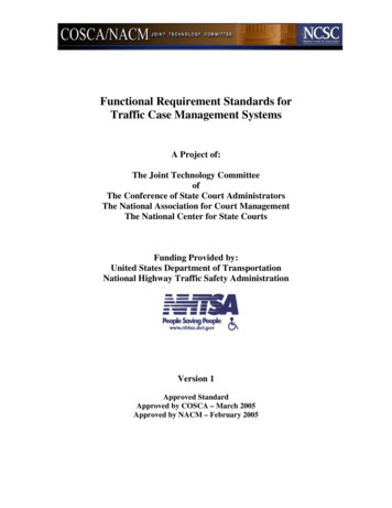
Advances in Engineering Research, volume 1707th International Conference on Energy and Environmental Protection (ICEEP 2018)Analysis on A Case of Marine Hydraulic Steering Gear FailureXiaohua YeQingdao Ocean Shipping Mariners College, Qingdao Shandong 266071, CHINAemail, yexhqmc@126.comKey Words: hydraulic steering gear, auxiliary machinery, steering mechanism, rudder bladeAbstract: The hydraulic steering gear is an important equipment of the ship and its failurecould contribute to navigation unsafely. With regard to the failure of a certain hydraulicsteering gear and inspection of the steering mechanism, this article specifies reasons forthe failure of the steering gear and puts forward methods including control to the design,selection and manufacture and enhancement to the watch-keeping and ship-repairing sothat the similar accidents could be avoided. In this case, the analysis and treatment to thefailure of the marine hydraulic steering gear could result in the prevention and eliminationto the failure.IntroductionThe marine hydraulic steering gear is an important equipment to control the course.Once a failure occurs and could not be eliminated in time, the course would not becontrolled and the navigation safety of the ship could also be affected. The failure ofsteering gear involves various aspects such as the design, use and maintenance, whichrequires a thorough analysis. [1-3] According to the failure of the steering gear of anocean-going ship, the failure of the steering gear is investigated in various aspects.Overview to the FailureThe ship is a double-bottom ocean-going oil tanker. The main parameters of the ship areas follows:Table 1 Main Parameters of the 01.9mGross3726 tLoad4881.27 tOverallTonnageMoulded16.0mNet Tonnage 1251 tSpeed12.0 m/hDepthMoulded8.0mSummer5.9mRudder SpadeBreadthWaterlineRudderThis ship sailed from Singapore to China. The steering gear was tested and corrected one hourbefore sailing. It took 14 seconds from one side 30 to the other side 35 . And it was normal. Aftera few days, an autopilot yaw alarm suddenly rang. The OOW confirmed the autopilot and the ship’sheading immediately and found that the bow shifted to the right. The rudder was switched tomanual position and the ship still yawed promptly. Turning to the emergency rudder, it didn’tanswer to the port and starboard rudder. The master ordered to slow down and stop the main engineand showed not under command light as well as deck light; besides, we broadcasted to other shipsin the vicinity with VHF16 and set AIS to the out of control state; meanwhile, we reported to thecompany's emergency response center. The ship is in a drifting state due to rudder failure.Failure AnalysisTroubleshootingThe failure of the steering gear is mainly due to failure of electrical and hydraulic system,steering mechanism and rudder blade. [4] The hydraulic system of this ship is shown in Figure 1.Copyright 2018, the Authors. Published by Atlantis Press.This is an open access article under the CC BY-NC license 389
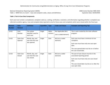
Advances in Engineering Research, volume 170The system is a pump-controlled closed hydraulic system, which consists of two sets of mainpumps, pipe systems and two pairs of working cylinders. During the voyage, the two main pumpsFig.1 Hydraulic System of Steering Gearare used as the standby pump for each other to improve the reliability of the equipment. The mainhydraulic components of the main circuit are as follows. (1) Unloading valve. It consists oftwo-position two-way solenoid divert valve 1 and logic valve 2. When starting, the main pumpunloads and starts. After startup is accomplished, the solenoid valve makes the system load andwork normally. (2) Kawasaki-style special-purpose valve. It is mainly composed of a lock valve 3on the fuel manifold, a pair of storm valves 4, and a bypass valve 5. The lock valve 3 on the fuelmanifold can prevent rudder angle from being out of control, the storm valve 4 can play a role intwo-way security, and the bypass valve 5 can functions to select working conditions of the steeringgear. (3) Automatic isolating valve 6. When the oil level of the certain tank is too low, the mainpump stops running while the isolating valve is energized, and the corresponding cylinder isbypassed. [5]According to the above analysis of the hydraulic system, the reasons why the steering gear cannotrotate effectively may be as follows:(1) Unloading valve fails and logic valve 2 still opens so that hydraulic oil flows directly back tothe tank instead of to the working cylinder.(2) Storm valve still opens which results in hydraulic fluid flows back to the tank. In that case,the oil pressure is insufficient to drive the steering mechanism.(3) Failure of the main or auxiliary oil pump results in insufficient oil pressure to drive thesteering gear.(4) Leakage of the cylinder is seriously so that the oil pressure could not be built up.With regard to the above analysis, thechief engineer checks the workingconditions of the steering gear hydraulicsystem in the steering gear room after thefailure. He finds that the hydraulic systemfunctions normally and the steering gearoperates normally as well. As a result,electrical faults and hydraulic systemfailures can be eliminated, and theunderwater part of the steering mechanismshould be taken into account.Fig. 2 Rudder Stock1390
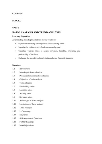
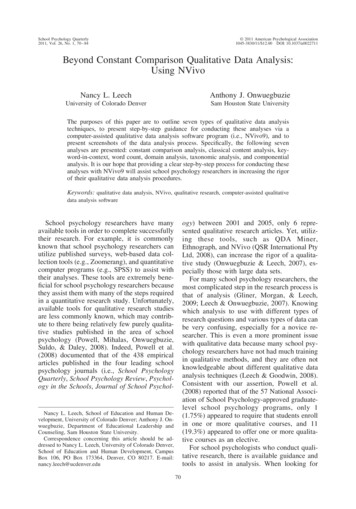
Advances in Engineering Research, volume 170Inspection to Underwater Part of Steering GearThe underwater part of the steering gear is inspected and the rudder blade of the steering gearfound lost. The ship immediately proceeds to the shipyard for repair and makes further inspection tothe underwater part which is as follows:(1) Inspection to the rudder stock: The length overall of the rudder stock is 5925mm, diameter430mm, and the surface is in good condition. There is no wear, strain or deformation. The keywayis approximately normal, which is shown in Figure 2.(2) Inspection to the fixed parts of the rudder stock: The tightening nut on the rudder blade isM260*6 and the height is 210mm. No tightening nut is found during the inspection; the crest of thescrew part of the rudder stock is damaged, and the bottom of the rudder stock is flat. As shown inFigure 3 and Figure 4.Fig.4 Rudder Stock BottomFig.3 Rudder Stock Screw(3) The rudder system was maintained during the last special survey. The maintenance items ofthe “repair list of the rudder system” are as follows: During the docking repair, rudder cover platesare cut off and welded up; rudder stocks and bearing sleeves are inspected with clearance measured;rudder blade is disassembled and packing glands replaced; safety components of rudder stock nuts(φ500 300) are welded onto the rudder blade (drawing of the nuts safety component is not available,and they are installed temporarily on the spot for safety), rudder blade is not replaced or overhauled;rudder blade reassembling process is supervised by the surveyor, engineering superintendent, chiefengineer and chief officer. In accordance with the repair in the shipyard, nuts safety components arefitted on the basis of original rudder blade, which is superior to former one in terms of safety.Analysis on Causes of AccidentAccording to the above investigation and evidence-collection as well as analysis of technicalpersonnel on the spot, the causes that rudder blade lost are as follows:Analysis on External CauseFFNFLvFDFFLGcoursesteeringFDZXcXb(a)(b)Fig 5 Water Force to the Rudder & Effect on the Ship1391
Advances in Engineering Research, volume 170As shown in Fig.5, when the rudder blade diverted to a certain rudder angle α, the resultant forceof the water pressure acted on the rudder blade is expressed by FN, and the friction FT which isconsistent with the rudder blade center line occurred between the water stream and the rudder blade.The total force of the water is F which is the resultant force between FN and FT. The water force Fcan also be decomposed into a lift FL which is perpendicular to the direction of the water flow and aresistance FD which is parallel to the direction of the water flow.The torque developed by the water force F of the rudder and the center of gravity G of the rudderis called the moment of turning ship, which is represented by MS. Because the moment arm of forcebetween FD and the ship's center of gravity G is small, the moment of turning ship can be expressedapproximately as1MS FL l C L ρAv 2 l2Nm(1)In this formula: CL—lift coefficient; ρ—water density, Kg/ m3 A—rudder blade area; V—watervelocity at the rudder blade, m/s; L—distance between center of rudder pressure and center ofgravity, m.The hydrodynamic moment of the rudder is the torque of water pressure FN acted on rudderopposite to the rudder stock axis, denoted by Ma.1Ma FN χ C C N ρAv 2 χ C2Nm(2)In this Formula: XC--the distance between the pressure center of the rudder and the axis of therudder stock, m; CN、CX--the pressure coefficient and pressure center of the rudder blade; b--theaverage width of the rudder blade, m; Z—the distance between the axis of rudder stock and edge ofthe rudder blade, m.The water area of the incident is located at a distance of 3 n miles from the nearest land. The seais vast with depth 177 meters. The wind over the sea is northeastern with grade 4, so as to the wave,and the ocean current is about 3 knots to the south. There are no obstacles such as sunken ships,islands or reefs at the fairway. The navigation and weather conditions are normal. According to theanalysis of stress, the speed and current at the time of the incident is slow, that is, the water velocityV at the rudder blade is not fast. When the ship turns the rudder, the required moment of turningship MS and consequently the hydrodynamic moment is small. Therefore, the total force F of actedon the rudder blade and the stress of the rudder stock are also not large enough to cause damage tothe rudder blade. Because none of hazardous situations such as collision, ground or rough seaoccurred previously, the external cause to lose the rudder blade could also be eliminated.Analysis on the Reason of DesignSealCap NutFig.6 Sealing and Tightening of Rudder BladeIn accordance with referring to the drawings of the rudder blade, it is found that no interlockdevice fitted between the blade and the tightening nut of the stock. Only one φ440 φ270 16mm1392
Advances in Engineering Research, volume 170shim made from No. 35 steel is shown in the design drawing. If there is a problem with the gasket,the pre-tightening force of the rudder stock nut may be insufficient and loose consequently. As aresult of its own weight, relative motion could happen among the rudder post, blade and the nut(Figure 6).Failure of Sealing Leads to Leakage of Seawater with Resultant Corrosion and Rudder BladeLooseningAccording to the investigation to the corrosion on the cone surface of the rudder blade as well asdrawings and analysis to the repair during special survey, we could suspect that leakage into thelower chamber along the keyway and “trachoma” which is caused by the bad sealing effect betweenrudder stock and rudder blade (sealing device shown in Figure 6) or inferior sealing quality of thecover plate during welding operation. Both of rudder stocks and gaskets are made of 35 steel andthe hardness is HB150 185. Once leaked into the seawater, the gasket will be corroded firstly. Asthe shim continues to corrode, the pre-tightening force of the rudder stock nut decreases; meanwhile,the break of rudder stock nut and threads also corrode to different extent. Because the nut safetydevice is welded on the rudder blade leading to the breaking effect of the rudder nut safety devicereduced, the nut is subject to great variable friction as the rudder blade rotates to port side andstarboard side. When the rudder blade rotates to port side, the rudder stock nut is forced todisengage and the rudder stock nut cannot be tightened when rotating to the starboard side, so thelock nut loosens gradually. When the rudder stock lock nut is retracted to a certain position, the nutis damaged instantaneously by 7 to 8 tons gravity force of rudder blade, resulting in drooping-off ofthe rudder blade. In a word, the cause leading to loss of the rudder blade is more complex andinvolves various aspects: the rudder stock nut is lack of breaking device at the design stage; sealingeffect of the unit deteriorates or welding quality of the cover plate is inferior; meanwhile, seawatermay flow into the nut chamber to lead to corrosion as this part is below the waterline permanently,so the pre-tightening force of the nut could decrease. As various factors exist together, the nut losesfastening effect correspondingly, which is the main cause of this incident.ConclusionsAccording to the analysis on the failure of the hydraulic steering gear, we should do followingprecautions to prevent such accidents from occurring:(1) During the process of design, site selection and manufacturing, the steering gear should bepaid attention thoroughly by professional and technical personnel. The fix between nut and gasketshould be thickened, and the nut breaking device be fitted as well. Meanwhile, the installed rudderblade should be tested for defection or sealing if applicable.(2) Inspections to the watch-keeping should be enhanced. During the routine inspection andmaintenance, the common methods should be taken to detect the defections and faults properly andappropriate repair measures should be made as soon as possible.(3) Control to the quality of working skills and critical equipments should be strengthened duringship repairing period. Measures should be taken to the management of abnormal process and spareparts which is related to the quality of equipment. Inspections should be made to the rudder blade,rudder stock nut and gasket thoroughly, and reliability of the breaking device should be confirmed.References[1]ZHENG Zhi-guo, LI Cheng-fu. The Measures of Steering Gear Failure. Journal of QingdaoOcean Shipping Mariners College,2014,35(4):5-7.[2]HE Fa-ming. Failure Analysis and Improvement on the Steering Gear Hydraulic System of aShip. Chinese Hydraulics & Pneumatics,2014,(2):109-111.[3]LUO Zhi-ming, LIANG Si-yuan. Debugging and Malfunction Analysis for Steering GearSystem of Large Vessel. Marine Technology,2016,330(2):83-89.[4]HOU Chengguang,YUAN Zhaohui, HE Changji.Reliability Analysis of Electro-hydralicActuator Based on Fuzzy Fault. Machine blade Tool and Hydraulics,2007,35(6):226-227.1393
Advances in Engineering Research, volume 170[5]WANG Jin-xiang, YAN Zhong-ping. Dicussion on Fault Diagnosis from a Case of Steering GearFault .Marine Technology,2011,(1):55-57.1394
According to the above analysis of the hydraulic system, the reasons why the steering gear cannot rotate effectively may be as follows: (1) Unloading valve fails and logic valve 2 still opens so that hydraulic oil flows directly back to . Failure of the main or auxiliary oil pump results in insufficient oil pressure to drive the steering gear .