Transcription
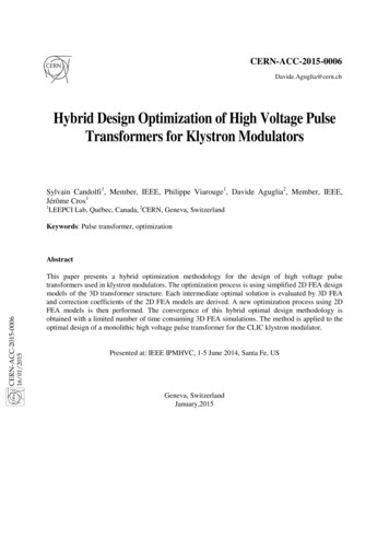
Proceedings of the World Congress on Engineering 2016 Vol IIWCE 2016, June 29 - July 1, 2016, London, U.K.Design and Optimization of the SteeringSystem of a Formula SAE Car UsingSolidworks and Lotus SharkSadjyot Biswal, Aravind Prasanth, M S Dhiraj Sakhamuri and Shaurya Selhi, Member, IAENG Abstract— The main aim of this paper is to design thesteering system for a formula SAE vehicle. The main focus is todesign a steering system such as to counter bump and roll steerand ensure proper response to high speed and low speed turns.The design process consists of first determining the steeringparameters and geometry and then analyzing it in lotus sharksuspension analyzer. After analysis and optimization of thegeometry the entire system is designed in Solidworks.Index Terms— Steering, FSAE, Ackermann, LOTUS Shark,SOLIDWORKSTI. INTRODUCTIONHE steering system of a Formula SAE car is of theutmost importance as it has to have a good reaction toall turns and corners at the event. The steering system is alsoone of the most key designs for overall handling andstability of the car.The steering system should be such that the driver canactually sense what is happening at the front tires. Theentire system must be designed in such a way that thecomponents must be able to take all the load. The steeringsystem should be responsive enough to high speed as wellas low speed turns and also possess some self-returningaction.The steering parameters like castor angle, kingpin angle,scrub radius, mechanical trail etc. have to be kept in mindwhile designing and the best compromise for these valueshas to be found.As the Formula SAE event consists of more low speedcorners it was decided to use Ackermann steering geometryas in this geometry the inner tire turns more as compared tothe outer tire thus giving an added advantage for tracks withlow speed turns.Now since the geometry has been decided the percentAckermann has to be decided. 100% Ackermann wasconsidered to be the best solution for low speed maneuversbut due to compliance effects an Ackermann percent ofaround 60 to 80 percent was considered to be the bestsolution. The exact percent would be later decided onkeeping in mind packaging constraints and tie rod length.III. STEERING ABILITY REQUIREDTo calculate the rack, travel the steer angle required andsteering ratio need to be calculated.A simple model is used to determine approximate steeringangle required considering maximum radius of turn inFSAE events. The wheelbase of the car is 1550 mm and tireradius of turn to be used is 4.5m.II. DESIGNWhile designing, the major factor is the type of geometryto be used for the steering system. The three possiblegeometries that can be used are Ackermann, antiAckermann and parallel steer geometry.Figure 1. Steer angle for a simple modelManuscript received March 19, 2016; revised April 10, 2016.Sadjyot Biswal is studying at the Birla Institute of Science andTechnology Pilani, Dubai, PO. 345055 UAE (sadjyotbiswal9@gmail.com).Aravind Prasanth is studying at the Birla Institute of Science andTechnology Pilani, Dubai, PO. 345055 UAE (phone: 971 552140408;e-mail: aravind.prasanth@gmail.com).M S Dhiraj Sakhamuri is studying at the Birla Institute of Science iraj@gmail.com).Shaurya Selhi is studying at the Birla Institute of Science andTechnology Pilani, Dubai, PO. 345055 UAE (shauryaselhi@gmail.com)ISBN: 978-988-14048-0-0ISSN: 2078-0958 (Print); ISSN: 2078-0966 (Online)A. Final StageThe approximate steer angle is θ R/lWhere θ steer angleR wheelbaseL radius of turnWCE 2016
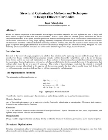
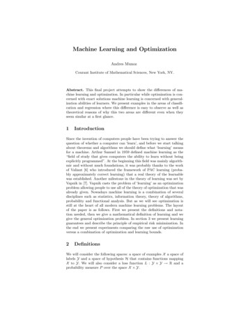
Proceedings of the World Congress on Engineering 2016 Vol IIWCE 2016, June 29 - July 1, 2016, London, U.K.V. RACK TRAVELθ 1.55/4.5 0.344 rad 19.71 degreesNow considering both the tires the steering angle has nowto be calculated taking into account that both tires turn by adifferent amount.Once the steering ratio has been calculated the rack travelneeds to be decided.The steering wheel decided is AIM Formula steeringwheel 2 which has a radius of 130 mm.The steering wheel travel for one complete rotation 2π x r 0.816mConsidering maximum steer angle and max rack travel isreached at complete rotation of the steering wheelThe steering ratio can be equated to steering wheeltravel/rack travel7.2 0.816/Rack travelRack travel 113.33 mmTherefore, required rack travel is around 114 mm.VI. RACK POSITIONFigure 2. Steer angle for Ackerman principleWhere:θo turn angle of the wheel on the outside of the turnθi turn angle of the wheel on the inside of the turnB track widthL wheel baseb distance from rear axle to center of massR (R12 B2)R12 R2 B2R1 (R2 B2)R 4.5B 1.55R1 4.43mR1 B/tan θi L/2R1 1.55/tan θi 1.195/2Ɵ1 22.02Through the calculations we can find out that for a turn ofmaximum radius 4.5 m the steer angle for the inner tire is22.02 degrees and the outer tire is 17.13 degrees.IV. STEERING RATIOThe steering ratio is the ratio of how much the steeringwheel turns in degrees to how much the wheel turns indegrees.Approximating maximum turn to be of 25 degrees andsteering wheel movement to be 180 degrees the steeringratio can be calculated asS.R 180/25 7.2ISBN: 978-988-14048-0-0ISSN: 2078-0958 (Print); ISSN: 2078-0966 (Online)The rack can have two positions. It can either be in front ofthe front wheel center line or behind it. If the rack is placedforward of the front axle line it can be mounted easily on theframe giving wide range for choice of heights. However,this arrangement makes it difficult to have the steering rack,track rods and steering arms in a straight line which isrequired if Ackermann geometry is a goal for steeringdesign. Fixing the rack behind the axle line is better fromboth a geometrical and packaging viewpoint. Hence it isdecided to have the rack positioned behind the front axleline i.e. a rear steer is chosen.VII. ACKERMAN PERCENTAfter the text edit has been completed, the paper is readyfor the template. Duplicate the template file by using theSave As command, and use the naming conventionprescribed by your conference for the name of your paper.In this newlyThe exact Ackermann percent can be calculatedaccording to the position of the steering arm or knuckles.The percent can be calculated but based on the fact thatparallel steer is 0%, and 100% is when the steering arms canbe projected back to the rear axle at the vehicle centerline,then the range from 0-100% is between this geometry.Current distance (where the lines projected meet) 961.19 mmDistance for 100% Ackerman 1496.38mmAckermann percent current distance/distance for 100percent x 100 percent 961.19/1496.38 x 100 64.23 %WCE 2016
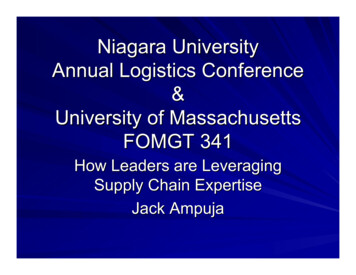
Proceedings of the World Congress on Engineering 2016 Vol IIWCE 2016, June 29 - July 1, 2016, London, U.K.The steering geometry had to be analyzed using a particularsoftware to determine the steering parameters for bestvalues of bump and roll steer. The software chosen wasLOTUS Shark suspension analyzer due to its ease of useand accurate results. The process used was to determine the2D suspension points in Solidworks and then input theminto LOTUS Shark analyzer. After the first set of pointswere entered into the software, a number of iterations werecarried out to determine the best possible values for thesteering geometry.Figure 3. Calculation of Ackerman %A. Analysis in Lotus SharkFigure 4. Front view geometry in LOTUS SharkSr.no.1234567891011121314151617PointsLower WishboneFront PivotLower WishboneRear PivotLower WishboneOuter Ball JointUpper WishboneFront PivotUpper WishboneRear PivotUpper WishboneOuter Ball JointPushrodWishbone EndPushrod RockerEndOuter Track RodBall JointInner Track RodBall JointDamper to BodyPointDamper to RockerPointWheel SpindlePointWheel CentrePointstRocker Axis 1PointndRocker Axis 2PointCentre of .297800280Figure 5. Suspension and steering geometry coordinates in LOTUS SharkISBN: 978-988-14048-0-0ISSN: 2078-0958 (Print); ISSN: 2078-0966 115.02698.1497Figure 6. Suspention and steering parameter values in LOTUS Shark .19‐0.2227Toe .331.321.311.3011.2911.2821.2731.2641.2551.246WCE 2016
Proceedings of the World Congress on Engineering 2016 Vol IIWCE 2016, June 29 - July 1, 2016, London, 1.1Figure 7. Suspention and steering parameter values in LOTUS Shark duringbumpAfter analysis in LOTUS Shark suspension analyzer thesteering parameters were finalized. The values wereKingpin Angle 8 degrees, Caster Angle 1.41 degrees,Mechanical trail 5.25mm.The trail gets the wheel to follow the steering axis andgives it the self-straightening properties. However too muchcan make the steering heavy so a trail of 5.25 mm wasfinalized.The kingpin inclination should be as close as possible tovertical to avoid unfavorable wheel camber changes whenwheel is being steered. The ideal situation is not possibledue to attain due to packaging requirements so a kingpinangle of 8 degrees has been chosen.A positive caster angle of 1.41 degrees was finalized forgood steer camber characteristics.B. Final DesignOnce the analysis in LOTUS Shark analyzer is completedand the geometry points have been finalized, the final 3-Ddesign of the entire steering system is completed inSolidworks. The final design consists of the Steering wheel,steering column, universal joints, rack and pinion, track rodand steering arm.steering force required should also be appropriate.The option of having a kingpin angle of 0 degrees wasnot possible as the resultant scrub radius was too high. Tokeep the scrub radius to a minimum some amount ofkingpin has to be added.Positive Castor angle was added into the system becauseit has a good impact on steer camber characteristics. Somemechanical trail should be there to help steer returncharacteristics but too much mechanical trail can wipe outthe effects of pneumatic trail. Pneumatic trail is importantfor the driver to sense tire wear characteristics. Therefore, aproper value of mechanical trail must be chosen.To avoid unfavorable bump steer characteristics, the tierod should point at the front view instantaneous center.IX. BUMP STEERBump steer is an undesirable characteristic resulting fromthe radial paths described by the upper and lower steeringaxis bearings based upon a different center than that of theouter end of the track rod during suspension movements.This effect can be reduced by arranging the upper and lowersteering axis bearings and keeping the inner track rodbearing to lie on the same line when viewed from the frontof the car.X. CONCLUSIONAfter all the calculations were completed and analysis inLOTUS Shark suspension analyzer was conducted the finalsteering assembly was designed in Solidworks. The abovepicture shows the final design incorporated into the chassisof the FSAE car.This steering system designed for the turns generallyencountered in the FSAE events was optimal to counternegative impacts of bump and roll steer and also possessedself-returning capability. Universal joints have been addedin the steering column to line it up nicely with the pinionshaft. It also provides for the columns to fold up in the eventof a hard frontal collision preventing it from being forcedinto the cockpit and injuring the driver.ACKNOWLEDGEMENTFigure 8. Final Sterring system design in solidworksFirstly, I would like to express my heartfelt gratitude tothe Director of BITS Pilani, Dubai Campus, Dr. Prof. R.N.Saha, who has ushered a new light on our college.Next, I would like to thank the Department ofMechanical engineering, BITS Pilani Dubai campus fortheir motivation, support, guidance and encouragementthroughout the course of this projectREFERENCESVIII. STEERING PARAMETERSSome important parameters have to be considered indesigning the steering geometry. The steering geometryshould be responsive enough both in bumps and roll andshould also possess some self-returning capability. TheISBN: 978-988-14048-0-0ISSN: 2078-0958 (Print); ISSN: 2078-0966 (Online)[1][2]William F. Milliken and Douglas L. Milliken, 1995, “Race CarVehicle Dynamics”, Society of Automotive Engineers, Inc.Gaffney, Edmund F., and Anthony R. Salinas. Introduction toFormula SAE Suspension and Frame Design. No. 971584. SAETechnical Paper, 1997.WCE 2016
Proceedings of the World Congress on Engineering 2016 Vol IIWCE 2016, June 29 - July 1, 2016, London, U.K.[3]Robertson, Dennis, and George J. Delagrammatikas. The suspensionsystem of the 2009 cooper union FSAE vehicle: A comprehensivedesign review. No. 2010-01-0311. SAE Technical Paper, 2010.[4] Gillespie, Thomas D., Fundamentals of Vehicle Dynamics. Society ofAutomotive Engineers, Inc., Pennsylvania, 1992.[5] Smith, Carroll, Engineer to Win. MBI Publishing Company,Minnesota, 1984.[6] Norton, R. Machine design. Pearson Prentice Hall, Upper SaddleRiver, NJ, 2006.[7] Heisler, H. (1989), Advanced Vehicle Technology, Arnold, 338Euston Road, London NW1 3BH[8] Fenton, J. (1980), Vehicle Body Layout and Analysis, MechanicalEngineering Publications Ltd. London[9] Smith, C. (1978), Tune to Win: The Art and Science of Race CarDevelopment and Tuning, Aero Publishers, Inc. 329 West AviationRoad, Fallbrook, CA 29028[10] Vehicle Dynamics Terminology- SAEJ670, Revise 07-1976.[11] Pashley, T. (2008). Hoe to Build Motorcycle-engined racing cars, UK,Veloce PublishingISBN: 978-988-14048-0-0ISSN: 2078-0958 (Print); ISSN: 2078-0966 (Online)WCE 2016
steering wheel movement to be 180 degrees the steering ratio can be calculated as S.R 180/25 7.2 V. RACK TRAVEL Once the steering ratio has been calculated the rack travel needs to be decided. The steering wheel decided is AIM Formula steering wheel 2 which has a radius of 130 mm. The steering wheel travel for one complete rotation 2π x r