Transcription
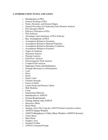
Introduction to ANSYS MeshingModule 3:Global Mesh ControlsDr. Ahmed Nagib Elmekawy
Global Mesh ControlsWhat you will learn from this presentation 2Introduction to Global Mesh ControlsDefaultsGeneral Sizing Controls & Advanced Size FunctionsGlobal InflationAssembly Meshing ControlsStatistics
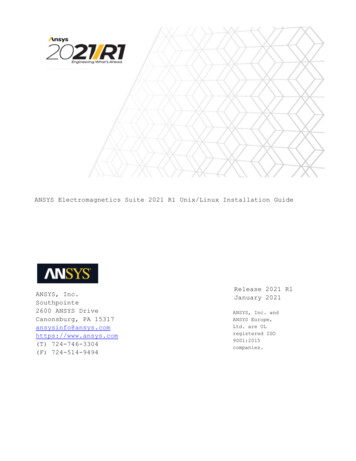
Preprocessing WorkflowGeometry CreationORGeometry ImportSketches andPlanes3D OperationsExtrude, Revolve,Sweep, etcGeometry ImportOptionsDirect CAD/BiDirectional CADGeometryOperations3D OperationsBoolean, BodyOperations, Split,etcMeshingMeshingMethodsHybrid Mesh: Tet,Prisms, PyramidsHexa Dominant,Sweep meshingGeometryCleanup andRepairAssemblyMeshingAutomaticCleanupGlobal MeshSettingsMerge, Connect,Projection, FlowVolumeExtraction, etcLocal MeshSettingsSizing,Body/Sphere ofInfluence, MatchControl, etc3Solver
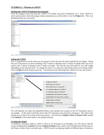
Meshing Process in ANSYS Meshing4
Global Mesh Controls (1) Global mesh controls are used tomake global adjustment in themeshing strategy, which includessizing functions, inflation, smoothing,defeaturing, parameter inputs,assembly meshing inputs, etc. Minimal inputs– Automatically calculates globalelement sizes based on the smallestgeometric entity– Smart defaults are chosen based onphysics preference Makes global adjustments forrequired level of mesh refinement Advanced Size Functions for resolvingregions with curvatures andproximity of surfaces5Smartdefaults !
Global Mesh Controls (2)Physics Based Settings Physics and Solver PreferencesGlobal Mesh Sizing Controls Relevance and Relevance Center Advanced Size Functions Smoothing and Transition Span Angle Center Curvature Normal Angle Proximity Accuracy and Cells Across GapInflation Inflation Option, Inflation Algorithm Collision Avoidance Maximum Angle, Fillet Ratio, SmoothingAssembly Meshing Activation of CutCell/Tetrahedrons MeshingPatch Confirming Options Activation of Advancing Front MethodAdvanced Shape Checking Element midside nodesDefeaturing Pinch based Automatic Mesh BasedStatistics Mesh statistics, Quality criteria6
Global Mesh Controls (3)7
Defaults 8Four options under “Physics Preference”– CFD, Mechanical, Explicit and Electromagnetic Three options under “Solver Preference” when CFD isselected:– Fluent, CFX andPOLYFLOW Mesh setting defaults are automatically adjusted to suit the“Physics Preference” and “Solver Preference” Assembly Meshing is active only when Physics Preference isCFD and Solver Preference is Fluent
Defaults : RelevanceRelevance and Relevance Center Useful for automatic Global Refinement or Coarsening ofthe meshRelevance CenterCoarse-100-100-1000001009FineMedium100100
Sizing : Advanced Sizing Functions Controls the growth and distribution of mesh in importantregions of high curvature or close proximity of surfaces Five Options:– Off.– Proximity and Curvature– Curvature– Proximity– Fixed
Sizing : Advanced Sizing Function (ASF) ExamplesASF: OffASF: CurvatureASF: Proximity The edges are meshedwith global Element Size Then the edges arerefined for curvature and2D proximity At the end, correspondingface and volume mesh isgenerated Determines the Edge andFace sizes based onCurvature Normal Angle Finer Curvature NormalAngle creates finer surfacemesh Transition of cell size isdefined by Growth Rate Controls the mesh resolutionon proximity regions in themodel Fits in specified number ofelements in the narrow gaps Higher Number of CellsAcross Gap creates morerefined surface mesh Transition of cell size isdefined by Growth Rate Transition of cell size isdefined by Transition11
Sizing : Advanced Sizing Function ExamplesASF: Proximity & CurvatureASF: FixedASF: Fixed Local Sizings Combines the effect of‘Proximity’ and ‘Curvature’size function Constant mesh size throughout No refinement due tocurvature or proximity in themodel Surface mesh is generatedwith specified Max FaceSize Volume mesh is generatedwith specified Max Size Mesh is refined locally due tosizing (on 2 edges for thatexample) Elsewhere size is defined byMax (Face) Size Transition of cell size isdefined by Growth RateMore computational time12
Sizing : Element SizeElement Size Element size used for the entire model– This size will be used for meshing all edges, faces and bodies Default value based on Relevance and Initial Size Seed– User can input required value as per geometry dimensionsElement size optionavailable when AdvancedSize Function is not used13
Sizing : Min and Max SizeMin Size Minimum element size that the size function will generate Some element sizes may be smaller than this size depending onthe edge lengthMax Face Size Maximum face size that the size function will generateMax Size Maximum element size that can be grown in the interior ofvolume meshMouse Pointer serves to estimatemesh sizesMin SizeMax Face SizeMin Size Max Face Size Max Size14Max Size
Sizing : Growth Rate Define the ratio between sizes of adjacent cells– On surfaces and inside the volumesGrowth Rate 1.1Growth Rate 1.2 (Default)Growth Rate 1.3Mesh size:GR 1.1 : 1,263,297 cellsGR 1.2 : 587,026 cellsGR 1.3 : 392,061 cells15
Sizing : Transition Controls the rate at which elements grow Two level control for transition– Slow (Default for CFD, Explicit), produces smooth transitions– Fast (Default for Mechanical and Electromagnetic), produces moreabrupt transitions Hidden for sheet models, ignored for assemblies containingsheets, when ASF is OnFast16Slow
Sizing : Smoothing Improves quality by moving locations of nodes with respect tosurrounding nodes Three level control for smoothing iterations– High (Default for Explicit)– Medium (Default for Mechanical, Electromagnetic and CFD)– Low For Cutcell meshing, the Smoothing option controls the qualitythreshold at which it will start smoothing. High is recommended.Low17MediumHigh
Sizing : Span Angle Center Controls curvature based refinement for Edges Three options and corresponding span angle ranges are– Coarse: 91 to 60 – Medium: 75 to 24 – Fine: 36 to12 FineMediumCoarse18
InflationInflation Used to generate thin cells adjacent to boundaries Required for capture of wall adjacent boundary layers– Resolve viscous boundary layer in CFD– Resolve thin air gaps in Electromagnetic analysis– Resolve high stress concentration regions in Structures Cells are created by ‘inflating’ from the surface mesh into thevolume (3d) or inflating from the boundary edge onto the face (2d) Options to control growth19
Inflation : Automatic Inflation Three options– None Select this for manual inflation settings using local meshcontrols– Program Controlled All the faces are selected for inflation except: Faces scoped to a Named SelectionFaces with manual inflation definedFaces in contact regionsFaces in symmetryFaces that belong to a part or body that has a mesh methoddefined that does not support 3D inflation, such as hexdominant Faces in sheet bodies– All Faces in chosen Named Selection: can grow inflationlayers from faces grouped in one named selection20
Inflation : Inflation OptionsFive options:SmoothSmooTransition thTransitionAll available for PC tets and Assembly meshingSmooth TransitionMaintains smooth volumetric growthbetween each adjacent layer. Totalthickness depends on the variation ofbase surface mesh sizes (Default)First Layer ThicknessMaintains constant first cell heightthroughoutTotal ThicknessMaintains constant total height of inflationlayer throughoutTotalThicknessLast AspectRatio21First Aspect RatioControls the heights of the inflation layersby defining the aspect ratio of theinflations that are extruded from theinflation baseLast Aspect RatioCreates inflation layers using the valuesof the first layer height, maximum layers,and aspect ratio controlsFirst LayerThicknessFirst AspectRatio
Inflation : Inflation Algorithms Two Algorithms– Post– PrePatch independentmeshes use PostPost First Tet grows then Inflation process starts Tet mesh is undisturbed, if the inflation options are altered Default option for Patch IndependentTetrahedronsPreview Inflationis available onlywith Pre AlgorithmPre Surface mesh is inflated first, then rest of the volume meshgrows Default method for Patch ConformingTetrahedrons22
Defeaturing Removes small geometry features meeting the tolerancesusing Pinch or/and Automatic Mesh Based Defeaturingcontrols in order to improve the mesh quality. Not allmeshing methods can take advantage of these controls Automatic Mesh Based Defeaturing (AMBD) when it is ‘On’,features smaller than or equal to the value of DefeaturingTolerance are removed automaticallyAMBD Off23AMBD On
Statistics Option to view the mesh quality metricExhaustive list of quality metricsOrthogonal Quality mesh quality metricsOption to view the Mesh Metric chart– Intuitive controls available under Mesh Metric Chart– Various options to explore under the ‘Controls’ See Module 5 for details24
Parallel Statistic Calculations25 Note that statistics can utilize multi-core machines tospeed up calculations in parallel Specify your core count in Tools Options to allow this Note that options set here will be remembered for futuresessions so you can set physics preference default etc here.
Workshop 3 – Global Mesh Controls26
Introduction to ANSYS MeshingModule 4:27Local Mesh Controls
Local Mesh ControlsWhat you will learn from this presentation Local mesh controls (Mesh sizing, Refinement, Match control, Inflation, etc) How to apply local controls? Effect of local controls on mesh28
Preprocessing WorkflowGeometry CreationORGeometry ImportSketches andPlanes3D OperationsExtrude, Revolve,Sweep, etcGeometry ImportOptionsDirect CAD/BiDirectional CADGeometryOperations3D OperationsBoolean, BodyOperations, Split,etcMeshingMeshingMethodsHybrid Mesh: Tet,Prisms, PyramidsHexa Dominant,Sweep meshingGeometryCleanup andRepairAssemblyMeshingAutomaticCleanupGlobal MeshSettingsMerge, Connect,Projection, FlowVolumeExtraction, etcLocal MeshSettingsSizing,Body/Sphere ofInfluence, MatchControl, etc29Solver
Meshing Process in ANSYS Meshing30
Local Mesh ControlsControl the mesh locally Depends on the “Mesh Method” usedLocal Mesh Controls are: Sizing– For Vertex, Edge, Face and Body Contact Sizing– For Edge and face Refinement– For Vertex, Edge and Face Mapped Face Meshing– For Face Match Control– For Edge and Face Pinch– For Vertex and Edge Inflation– For Edge and FaceThe latest control added on a particularentityoverrides any prior controls31
SizingRecommended for locally defining the mesh sizesYou can only scope sizing to one geometry entity type at a time For example: you can apply sizing to a number of edges or a number of faces, but not a mix ofedges and faces.Four Types of Sizing option Element Size specifies average element edge length on bodies, faces or edgesNumber of Divisions specifies number of elements on edge(s)Body of Influence specifies average element size within a bodySphere of Influence specifies average element size within the sphereSizing options vary depending on the entity type chosenEntity/Option Element Size Number of Divisions Body of Influence Sphere of InfluenceVerticesxEdgesxxxFacesxxBodiesxxxOnly Element Size type is available forCutCell meshing32Advanced SizeFunction in Globalsettings should bedisabledRequires aCoordinatesystem forthe sphere
Sizing : EdgesSizing Type:Element SizeEdge meshed with constantelement size of 60mmSizing Type:Number of DivisionsEdge meshed with 10elementsThe Curvature Normal Angle and/or the GrowthRatemaybe not displayed depending on the ASF used33
Sizing : EdgesBias Type and Bias FactorSpecify the grading scheme and factor Bias Type: grading of elements towards one end, both ends, or the center Bias Option:– Bias Factor: is the ratio of the largest element to the smallest element– Smooth Transition: defined by Growth Rate which is ratio of size of anelement with size of previous element. (Growth Rate Bias Factor (1(n-1))34
Sizing : EdgesBehaviorSoft: Sizing will be influenced by global sizing functions such as those based onproximity and/or curvature as well as local mesh controlsHard: Size control is strictly adhered to Transition between hard edges (or any edge with bias) and adjacentedgeand face meshes may be abrupt Hard edges or edges with bias will override Max Face Size and Max SizepropertiesSoftHard35Influenced by globalProximity advancedsize function.No influence from otherglobal settings
Sizing : FacesElement SizeDefines the maximum element size on the faceFace meshed withconstant elementsizeEdge curvature isresolved36
Sizing : Body (volume)Element SizeDefines the maximum cell size on the BodyTetrahedron patchconforming meshCutCellmeshWithoutbody sizingWithoutbody sizingWith bodysizing37Body meshed with maxcell size definedWith bodysizing
Sizing : Sphere of InfluenceSphere of Influence : on Vertex– Available with or without Advanced Size Functions– Sets the average element size around the selected vertex– Inputs: Sphere radius and Element size Center of the sphere is defined by a model vertex Good resolution at the vertex The element size will be applied to all entitiesconnected to the selected vertex38
Sizing : Sphere of InfluenceSphere of Influence : on Bodies– Available with or without Advanced Size Functions– Constant element size is applied within the confinesof a sphere– Use coordinate system to define the center of theSphere39
Sizing : Bodies of InfluenceBodies of influence (BOI)– Lines, surfaces and solid bodies can be used to refinethe mesh– Accessible when ASF is OnLine BOIsSurface BOIWithout BOIsThe ‘Body of Influence’ itself will not be meshed40Solid BOI
Mapped Face Meshing Creates structured meshes on selected mappable surfaces– Mapped Face Meshing with advanced control is supportedfor Sweep, Patch Conforming, Hexa Dominant Quad Dominant and Triangles– Mapped Face Meshing with basic control is supportedfor MultiZone Uniform Quad/Tri and Uniform Quad– RMB on Mesh and Show/Mappable Faces to display allmappable facesIf Mapped Face Meshing fails, ( ) icon appears adjacent to corresponding objectin the Tree outline. The mesh will still be created but will ignore this control.41v
Mapped Face Meshing: Vertex Type ‘Side’, ‘Corner’ and ‘End’ controls for vertices, to define strategyforMapping42Vertex TypeIntersecting Grid LinesAngle BetweenEdgesEnd00 — 135 Side1136 — 224 Corner2225 — 314
Mapped Face Meshing: ExampleEE EEE ESEEEESEEEEEEVertex type is dependant to the attached face the mesh can be individually controlled on all faces43
Mapped Face Meshing: Radial No. of Divisions If face is defined by two loops, then the “Radial Number of Divisions”field is activated Specify the number of divisions across the annular region Useful for creating number of layers across an annulusMapped face is swept to createpure hex mesh44
Match Control Define periodicity on faces (3D) or edges (2D) The two faces or edges should be topologically and geometrically the sameA match control can only be assigned to one unique face/edge pairMatch controls are not supported with Post Inflation AlgorithmMatch Control with Patch Independent tetrahedrons not supported yet– Two types of match controls available: Cyclic and Arbitrary– Not available for CutCell meshingMatching facemeshIf ‘Match Control’ fails, ( ) icon appears adjacent to correspondingobject in the outline Tree, however the mesh is created ignoring it45
Match Control: Cyclic Define Rotational periodicFull ModelCut BoundariesPeriodic ModelModel is symmetrical at 90 so slice the body along dotted lines in DesignModelerSelected Facesfor Match controlMatching facemesh46
Match Control: Arbitrary Two faces or edges to be matched, can be arbitrarily locatedFull Model : Tube BanksSymmetric Periodic ModelFace Mesh before ‘Match Control’Model extracted through ‘Slice’operation in DMFace Mesh after ‘Match Control’Coordinate systems needto be suitably defined atthe faces to be matched47Matching face mesh
Pinch To improve quality Pinch controlremoves small features (edges ornarrow regions) at the mesh level The Pinch feature is supportedfor the following mesh methods: Patch Conforming TetrahedronsThin Solid SweepsHex Dominant meshingQuad Dominant Surface MeshingTriangles Surface meshing– Not supported for CutCellmeshing– More details in lecture 5 “MeshQuality”48
InflationUsed to generate prism layers (as explained in Global settings chapter)Inflation layer can be applied to faces or bodies using respectively edgesorfaces as the boundaryInflation layer grown on edge boundary (red)Inflation layer grown on face boundary (red)49
Workshop 4 – Local Mesh Controls50
AppendixContents 51Edge, Face & Body Sizing OptionsSizing: Sphere of InfluenceContact SizingRefinementInflationObject generator for copying mesh settings to like bodies
Edge, Face and Body Sizing OptionsCurvature Normal AngleMaximum allowable angle that one element edge is allowed tospanAvailable only when Use Advanced Size Function is set to either On: Proximity and Curvatureor On: CurvatureYou can specify a value from 0 to 180 degrees or accept the default. (A value of 0 resets theoption to its default.)The default is calculated based on the values of the Relevance and Span Angle Center optionsGrowth RateRepresents the increase in element edge length with each succeeding layer of elements. (Forexample, a growth rate of 1.2 results in a 20% increase in element edge length with eachsucceeding layer of elements.)Available when Use Advanced Size Function is onSpecify a value from 1 to 5 or accept the defaultThe default is calculated based on the values of the Relevance and Transition optionsMust be always lower or equal the global growthrate52
Sizing : Sphere of InfluenceSphere of Influence : on Edges– Available only if Advanced Size Function is OFF– Use coordinate system to define the center of the SphereMesh on the entity and otherproximity entities that lies withinthe sphere of influence is affected53
Sizing : Sphere of InfluenceSphere of Influence : on Faces– Available only if Advanced Size Function is OFF– Elements within the sphere will have given average elemen t size– Use coordinate system to define the center of the sphere54
Contact Sizing Generates similar-sized elements on contact faces between parts– Two options Element Size. The size of the elements on contact faces respects the valueof Element Size specified Relevance. The size of the elements on contact faces are determinedinternally by spheres of influence with automatic determination of radiusand size depending on the value of specified Relevance– Not available for CutCell MeshingMesh withoutContact Sizing55
Contact Sizing Note that the mesh is still non-conformal across the contact region To insert a Contact Sizing in the Mesh tree select the contact regionfrom Contacts list and drag it to Mesh object, or use RMB on theMesh56
Refinement Valid for only for faces or edges Not available for Patch Independent Tetrahedrons, CutCell, UniformUniform Quad meshing methodsQuad/Tri Refinement is applied after the creation of mesh with rest of thesettings Refinement level can vary from 1 (minimal) to 3 (maximum) A refinement level of “1” breaks up the edges of the elements into half– The Refinement control may be automatically suppressed when use inflationdepending on how the inflation/refinement is used. See the user’s Guide for detailsResultant mesh may be of poor qualityOnly the selected face is affected and rest is almost unchanged57
InflationTransition Ratio: Attempts to match the sizeof last prism layer with thatof next Tet cellGrowth Rate: It determines the relativethickness of adjacent inflationlayersDefaults:58Transition Ratio: 0.5Growth Rate: 1.2Transition Ratio: 0.8Growth Rate: 1.2Transition Ratio: 0.27Growth Rate: 1.1Transition Ratio: 0.27Growth Rate: 1.4Transition Ratio: 0.272Growth Rate: 1.2
Object Generator Object generatorallows user to copy tree objects attached toan entity to several entities. Entities may or may not be similar. However, this works best forcopying mesh settings on similar entities. With mesh controls, it provides an easy way to assign similarcontrols to a group of objects.In this example, multiple mesh controls areused to define mesh for a bolt body59There are 4 similar bolt bodies onwhich these mesh settings can becopied easily using Object Generator
Object Generator To use the Object Generator:– In the standard toolbar, click the View Object GeneratorGenerator window.button to view the Object– In the Tree Outline, select the mesh control to becopied.– In the Geometry window, select the geometry to which the mesh control should be copied in theObject Generator window.– In the Object Generator window, select any required options and press Generate.For mesh controls requiring multiple geometry,primary set of entities should be selected in“Generate From”. The entities for rest of theinputs can be grouped in Named Selections.For example, in this case input for “Source”comes from set of source faces grouped in“Source Faces” Named Selection. This can becreated based on instance information if it exists,or similar sized faces, etc. See slides on NamedSelection Worksheet. Similarly, Named Selectioncan be provided for “Target”.60
Object GeneratorFor copying inflation settings, two sets of entities will be required, first one for “Geometry” onwhich inflation needs to be applied and second one for “Boundary”. Here, set of faces for“Boundary” is grouped in “INF” Named Selection.61
Introduction to ANSYS MeshingModule 5:62Mesh Quality
Mesh QualityWhat you will learn from this presentation 63Impact of the Mesh Quality on the SolutionQuality criteriaMethods for checking the mesh qualityTools to improve quality in MeshingPinchVirtual topology
Preprocessing WorkflowGeometry CreationORGeometry ImportSketches andPlanes3D OperationsExtrude, Revolve,Sweep, etcGeometry ImportOptionsDirect CAD/BiDirectional CADGeometryOperations3D OperationsBoolean, BodyOperations, Split,etcMeshingMeshingMethodsHybrid Mesh: Tet,Prisms, PyramidsHexa Dominant,Sweep meshingGeometryCleanup andRepairAssemblyMeshingAutomaticCleanupGlobal MeshSettingsMerge, Connect,Projection, FlowVolumeExtraction, etcLocal MeshSettingsSizing,Body/Sphere ofInfluence, MatchControl, etc64SolverCheck MeshQuality
Meshing Process in ANSYS Meshing65
Impact of the Mesh QualityGood quality mesh means that Mesh quality criteria are within correct range– Orthogonal quality Mesh is valid for studied physics– Boundary layer Solution is grid independent Important geometric details are wellcapturedBad quality mesh can cause; Convergence difficulties Bad physic description Diffuse solutionUser must Check quality criteria and improve grid if needed Think about model and solver settings before generating thegrid Perform mesh parametric study, mesh adaption 66
Impact of the Mesh Quality on theSolution Example showingdifference between amesh with cellsfailing the qualitycriteria and a goodmesh Unphysical values invicinity of poorquality cells67
Impact of the Mesh Quality on the Solution Diffusion exampleMesh 1(max,avg)CSKEW (0.912,0.291)(max,avg)CAR (62.731,7.402)VzMIN -90ft/minVzMAX 600ft/minLarge cell sizechangeMesh 2(max,avg)CSKEW (0.801,0.287)(max,avg)CAR (8.153,1.298)VzMIN -100ft/minVzMAX 400ft/min
Grid DependencyNb Cells Solution run withDP 0DP 1DP 25003 00024 000DP 0DP 3190 000 x8DP 41.5 MDP 3multiple meshes Note : For all runs thecomputed Y is validfor wall function (firstcell not in laminarzone)2%69
Grid Dependency Hexa cells can be stretched instream direction to reducenumber of cells Bias defined on inlet andoutlet walls Bias defined on inlet edges– 16 000 cells ( DP2)– Delta P 310 Pa ( DP3)70
Hexa vs. Tetra Hexa: Concentration in one directionHexa– Angles unchanged Tetra: Concentration in one direction– Angles change Prism: Concentration in one directionTetra– Angles unchanged Solution for boundary layerresolutionPrism– Hybrid prism/tetra meshes– Prism in near-wall region, tetra in volume– Automated– Reduced CPU-time for goodTetra (in volume)boundary layer resolutionPrisms (near wall)71
Mesh Statistics and Mesh MetricsDisplays mesh information for Nodes and ElementsList of quality criteria for the Mesh Metric Select the required criteria to get details for quality It shows minimum, maximum, average and standard deviationDifferent physics and different solvers have different requirements formesh qualityMesh metrics available in ANSYS Meshing include:––––––––Element QualityAspect RatioJacobean RationWarping FactorParallel DeviationMaximum Corner AngleSkewnessOrthogonal QualityFor Multi-Body Parts, go to corresponding body in Tree Outlineto get its separate mesh statistics per part/body72
Mesh Quality MetricsOrthogonal Quality (OQ)Derived directly fromOn cellOn faceA1Fluent solver discretization For a cell it is the minimum of:Ai f i Ai f i Ai ci Ai ci computed for each face iA1c1f3c3e1c2f1f2A3e3A2e2A2A3Ai eiFor the face it is computed as the minimum of Ai ei computed for each edgeIWhere Ai is the face normal vector and fi is a vector from the centroid of the cell to the centroidof that face, and ci is a vector from the centroid of the cell to the centroid of the adjacent cell,where ei is the vector from the centroid of the face to the centroid of the edgeAt boundaries and internal wallsci is ignored in the computations of OQ730Worst1Perfect
Mesh Quality MetricsOptimal (equilateral) cellSkewnessTwo methods for determining skewness:1. Equilateral Volume deviation:Skewness optimal cell size cell sizeoptimal cell sizeApplies only for triangles and tetrahedronsActual cellCircumsphere2. Normalized Angle deviation: max e e min ,Skewness max 180 ee Where e is the equiangular face/cell (60 fortets and tris, and 90 for quads and hexas)– Applies to all cell and face shapes– Used for hexa, prisms and pyramids74 max min0Perfect1Worst
Mesh QualityMesh quality recommendationsLow Orthogonal Quality or high skewness values are not recommendedGenerally try to keep minimum orthogonal quality 0.1, or maximum skewness 0.95.However these values may be different depending on the physics and the locationof the cellFluent reports negative cell volumes if the mesh contains degenerate cellsSkewness mesh metrics spectrumExcellentVery 50-0.800.80-0.940.95-0.970.98-1.00Orthogonal Quality mesh metrics spectrum75UnacceptableBadAcceptableGoodVery 70-0.950.95-1.00
Aspect Ratio2-D: Length / height ratio: δx/δyδyδx3-D Area ratio Radius ratio of circumscribed / inscribedcircleLimitation for some iterative solvers A 10 100 (CFX: 1000)Large aspect ratio are accepted wherethere is no strong transversegradient (boundary layer .)76
Mesh quality: skewness Two methods for determiningskewness:1. Based on the equilateralvolume:optimal (equilateral) celloptimal cell size - cell size Skewness optimal cell sizecircumcircle Applies only to triangles andtetrahedra. Default method for tris and tets.actual cell2. Based on the deviation from anormalized equilateral angle: Skewness (for a quad) max Applies to all cell and faceshapes. Always used for prisms andpyramids.max90 90,90min maxmin24
Equiangle skewness Common measure of quality is based on equiangle skew. Definition of equiangle skew:maxmax180e, eeminewhere:––– largest angle in face or cell.min smallest angle in face or cell.e angle for equiangular face or cell.max e.g., 60 for triangle, 90 for square. Range of skewness:0best1worst maxmin
Mesh quality: smoothness and aspect ratio Change in size should be gradual (smooth).smooth changein cell sizelarge jump incell size Aspect ratio is ratio of longest edge length to shortest edgelength. Equal to 1 (ideal) for an equilateral triangle or a square.aspect ratio 1high-aspect-ratio quadaspect ratio 1high-aspect-ratio triangle26
Striving for quality A poor quality grid will cause inaccurate solutions and/or slowconvergence. Minimize equiangle skew:– Hex and quad cells: skewness should not exceed 0.85.– Tri’s: skewness should not exceed 0.85.– Tets: skewness should not exceed 0.9. Minimize local variations in cell size:– E.g. adjacent cells should not have ‘size ratio’ greater than 20%. If such violations exist: delete mesh, perform necessarydecomposition and/or pre-mesh edges and faces, and remesh.Value ofSkewnessCell able0.80-0.95 0.95-0.99poorsliver0.99-1.00degenerate
Grid design guidelines: resolution Pertinent flow features should be adequately resolved.flowinadequatebetter Cell aspect ratio (width/height) should be near one where flow ismulti-dimensional. Quad/hex cells can be stretched where flow is fully-developedand essentially one-dimensional.Flow DirectionOK!28
Grid design guidelines: smoothness Change in cell/element size should be gradual (smooth).smooth changein cell sizesudden changein cell size — AVOID! Ideally, the maximum change in grid spacing should be 20%: xi xi 1xi 1xi1.229
Grid design guidelines: total cell count More cells can give higher accuracy. The downside is increasedmemory and CPU time. To keep cell count down:– Use a non-uniform grid to cluster cells only where they are needed.– Use solution adaption to further refine only selected areas. Cell counts of the order:– 1E4 are relatively small problems.– 1E5 are intermediate size problems.– 1E6 are large. Such problems can be efficiently run using multipleCPUs, but mesh generation and post-processing may become slow.– 1E7
5 Global mesh controls are used to make global adjustment in the meshing strategy, which includ