Transcription
TitleRadon Monitor User’s GuideAccurate, Reliable, EconomicalModels 1028, 1029
User’s Guide, Radon Monitor Copyright 2016 by Sun Nuclear Corporation. All rights reserved.The information contained in this guide and the accompanying software programare copyrighted and all rights are reserved by Sun Nuclear Corporation. No partof this guide may be translated, reproduced, sold, or otherwise distributedwithout the prior written consent of Sun Nuclear Corporation.Sun Nuclear Corporation reserves the right to make periodic modifications of thisguide without obligation to notify any person or entity of such revision.This guide is written for:PC software:version 2.2.0Embedded firmware:version 1.0.9Document 1028011, Rev I, 18 August 2017Sun Nuclear Corporation3275 Suntree BoulevardMelbourne, FL 32940 USA 1 321-259-6862www.sunnuclear.comii
PrefaceDescriptionThe Continuous Radon Monitor is a detection device used to measure theconcentration of radon gas. The unit is designed for professional inspectors touse in homes and buildings. The device is EPA verified and radon proficiencyprograms approved.CAUTION: The Continuous Radon Monitor Model 1028 is intended to be usedonly for indoor applications of radon gas sampling. Using in an outdoorenvironment may cause errors due to humidity and extreme temperatures.Health and Safety InstructionsWARNING: To avoid risk of electric shock, this device must only beconnected to a supply mains with protective earth (ground).WARNING: Never use the device in an area that could containexplosive gases. A spark from inside the device could ignite anexplosion.To protect Radon Monitor performance and cable insulation, never pull on a cableto disconnect it. Always grasp the plug or connector.Do not permit water or any other liquids to spill onto the device.For instructions to report health or safety related concerns, see Reporting Healthor Safety Related Issues or Concerns on page 56.iii
Finding Additional InformationThe U.S. Environmental Protection Agency (EPA) maintains a comprehensiveradon website at http://www.epa.gov/radon/index.html where you can find EPAdocuments, brochures, and publications relating to radon, including: A Citizen's Guide to Radon: The Guide to Protecting Yourself and Your Familyfrom Radon. This guidance offers strategies for testing your home for radonand discussions of what steps to take after you have tested, as well asdiscussions about the risk of radon and radon myths. Consumer's Guide to Radon Reduction: How to Fix Your Home. This bookletis for people who have tested their home for radon and confirmed that theyhave elevated radon levels. This booklet can help with selecting a qualifiedcontractor to reduce the radon levels in the home, determining an appropriate radon reduction method, and maintaining a radon reduction system. Home Buyer's and Seller's Guide to Radon. This booklet is intended for anyone who is buying or selling a home, real estate and relocation professionals,home inspectors and others.iv
ContentsPreface . . . . . . . . . . . . . . . . . . . . . . iiiPrinter Switch Settings . . . . . . . . . . . 24Description . . . . . . . . . . . . . . . . . . . . . iiiHealth and Safety Instructions . . . . . iiiFinding Additional Information . . . . . ivComputer Operation . . . . . . . . . . 26About the Software . . . . . . . . . . . . .Set Up Software . . . . . . . . . . . . . . . .Prerequisites . . . . . . . . . . . . . . . . .Install Software . . . . . . . . . . . . . . .Connecting to Computer . . . . . . . . .Launch Software . . . . . . . . . . . . . . .Using Software to Retrieve Data .Closing Software . . . . . . . . . . . . . . .About the Main Screen . . . . . . . . . . .Main Screen - Inspection Tab . . . . . .Main Screen - Chart Tab . . . . . . . . . .Zooming In and Out . . . . . . . . . . .Moving the Chart . . . . . . . . . . . . .Main Screen - Pictures Tab . . . . . . .Main Screen - Checklist Tab . . . . . . .Menu Bar and Toolbar Functions . . .Data to/from Text File . . . . . . . . . .Monitor Settings Preferences . . . . .Preferences Screen - MonitorSettings Tab Details . . . . . . . .Report Printing Preferences . . . . . . .Preferences Screen – Print TabDetails . . . . . . . . . . . . . . . . . . .Printing Reports . . . . . . . . . . . . . . . .Introduction . . . . . . . . . . . . . . . . . . 1Parts . . . . . . . . . . . . . . . . . . . . . . . . . . .1Options and Accessories . . . . . . . . .2Connections . . . . . . . . . . . . . . . . . . . . .3Controls . . . . . . . . . . . . . . . . . . . . . . . .4Standalone Operation . . . . . . . . . . 5Position the Monitor . . . . . . . . . . . . . .5Install a Fresh Battery . . . . . . . . . . . . .5Replacing the 9V Battery . . . . . . . . .6Connecting the AC Adapter . . . . . . .7Turn on the Display . . . . . . . . . . . . . . .7Starting a Test . . . . . . . . . . . . . . . . . . .9Interrupting a Test . . . . . . . . . . . . . . . .9Displaying Average and Current . . . .10AVG or CUR During a Test . . . . . . .10AVG or CUR After Test . . . . . . . . .10Clearing Memory . . . . . . . . . . . . . . . .11Checking Unit Status . . . . . . . . . . . . .11Setting Up Parameters . . . . . . . . . . .12Character Set . . . . . . . . . . . . . . . . . . .14Display Turns Off Automatically . . . .14Clearing a Reset . . . . . . . . . . . . . . . . .15Low Battery Messages . . . . . . . . . . .15Low Battery with AC PowerConnected . . . . . . . . . . . . . . . . . . .15Low Battery Without AC PowerConnected . . . . . . . . . . . . . . . . . . .16Storage Under Power . . . . . . . . . . . cifications . . . . . . . . . . . . . . . . 46Recommended SystemRequirements . . . . . . . . . . . . . . . 46Models 1028 and 1029Specifications . . . . . . . . . . . . . . . 46Support and Maintenance . . . . . 48Portable Printer (Optional) . . . . . 17Maintaining Hardware . . . . . . . . . . .Repairs . . . . . . . . . . . . . . . . . . . . .Inspection . . . . . . . . . . . . . . . . . . .Storage . . . . . . . . . . . . . . . . . . . . .Cleaning . . . . . . . . . . . . . . . . . . . .Disposing and Recycling . . . . . . .Service and Calibration . . . . . . . . .Battery Life . . . . . . . . . . . . . . . . . .Maintaining Software . . . . . . . . . . . .Verifying Software Version . . . . . .Removing Software . . . . . . . . . . .Multiple Software Installations . . .Optional Serial Connection . . . . . . . .Serial Port Setup . . . . . . . . . . . . . .Printer - Parts . . . . . . . . . . . . . . . . . . .17Printer - Description . . . . . . . . . . . . . .17Printer Connection and Controls . . . .18Loading the Paper . . . . . . . . . . . . . . .19Printing a Report . . . . . . . . . . . . . . . .20Typical Printer Report . . . . . . . . . . . .21Movement . . . . . . . . . . . . . . . . . . .22Printer Battery Pack . . . . . . . . . . . . . .22Inserting the Battery Pack . . . . . . .22Removing the Battery Pack . . . . . .22Charging the Battery Pack . . . . . . .23Low Printer Battery Indication . . . .23Efficient Use of Printer Battery . . .23v4848484848484949494949495050
Regulatory Supplement . . . . . . . 55Connecting with a Serial Cable . . .50Port Selection . . . . . . . . . . . . . . . .51Radon Monitor Troubleshooting . . . .51System Errors . . . . . . . . . . . . . . . .52Contacting Sun Nuclear Support . . . .54Support Website . . . . . . . . . . . . . .54Warranty . . . . . . . . . . . . . . . . . . . . . .54Sun Nuclear Corporation Symbols . .Operator Responsibility . . . . . . . . . .Reporting Health or Safety RelatedIssues or Concerns . . . . . . . . . . .Modifications to Equipment . . . . . . .Interaction with Other ElectricalEquipment . . . . . . . . . . . . . . . . . .vi5556565656
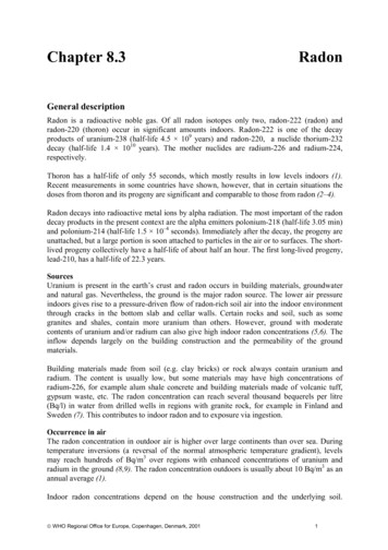
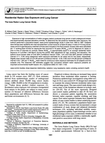
IntroductionPartsUnpack the radon monitor and identify the parts described below.Note: Save the packing material so it can be used when sending theradon monitor to Sun Nuclear Corporation for annual re-calibration.123No.123——Part NumberDescription1028300 or1028300-RMModel 1028 Radon Monitor* orModel 1028 Radon Monitor (Refurbished)801041ZCable, USB A-B M, 2 m741011**Power supply, 18 VDC, 100-240 VAC, 0.3A0200014Radon Customer Support Site letter (not shown)1028012Getting Started Guide (not shown)* Model 1029 Radon Monitor is obsolete.**Power supply P/N 741011 is only included with Model 1028 Radon Monitors shippedwithin the United States.Figure 1. Parts Furnished with Model 1028 Radon Monitor1
Options and AccessoriesContact Sun Nuclear Corporation to order any of the following accessories:Table 1. Radon Monitor AccessoriesPart NumberDescription1028050Printer, thermal, 80 column, Seiko DPU-414.022005ZPower supply for printer, 6 VDC. Used with P/N 801008Z.750052Rechargeable battery pack for printer (furnished with P/N 1028050 orcan be ordered separately).801008ZLine power cord for printer. Detachable, IEC Plug to USA style, 1.8 m.801032ZSerial cable for printer, 9-pin, D-connector, M/F (furnished withP/N 1028050 or can be ordered separately).850043ZThermal paper for printer (furnished with P/N 1028050 or can beordered separately).750004Battery, alkaline, 9V, for radon monitor.741011Power converter for Radon Monitors shipped within the United States,120 VAC to 12 VDC, 200 MA, 60 Hz.801041ZUSB cable for Radon Monitor, 2 m.1028012Radon Monitor Getting Started Guide.1028000-SCCarrying case, single radon monitor.1028000-SPCCarrying case, single radon monitor plus printer.1028000-DCCarrying case, dual (holds two radon monitors, printer, cables).102378Sign, self-adhesive, “Warning, Closed Building Procedure”.102379Sign, plastic, hanging, “Caution, Radon Test in Progress”.1028130Sign, vinyl static cling, “Warning, Closed Building Procedure”.2
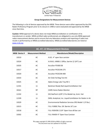
Connections12345NoDescriptionFunction1USB PC PORT (front)USB port (USB 1.1 or 2.0); for connection to a computer2Serial PC PORT (front)Serial port (RS-232); for connection to a computer3PRINTER PORT (front)Serial port (RS-232); for connection to the optional printer.4Power connection(back)Power connector; connects to the power supply whenusing AC power.5Battery compartment(back)Insert and connect a fresh 9V battery for either backup orprimary power. A fresh alkaline battery will operate theradon monitor for approximately 100 hours while a freshlithium battery will provide about 300 hours of operation.See Replacing the 9V Battery on page 6.Figure 2. ConnectionsWARNING: Always install a fresh 9V battery before test or storageto prevent the internal 3V battery (required for operation) fromdischarging.3
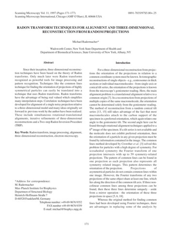
ControlsDescriptionFunctionDisplay16-digit LCD display shows messages to guide the operation.ButtonsSix push buttons with different functions depending on mode. Press keysto operate. Top row of labels lists main functions. Bottom row of labels arefor Setup. Print and Clear functions are used after measurement. Numbersare for PIN entry and Setup.STATUSSelects the Status mode, which scrolls through the Status settings.SETUPSelects the Setup mode, which is used to enter setup values from thekeypad.AVGDisplays the measured cumulative average radon gas concentration in pCi/lor Bq/m3 since the memory was last cleared.CURDisplays the measured short-term radon gas concentration, a rolling average of the most recent 12 hours.ONPress to turn on the display. There is no OFF switch. To save power, the display turns off automatically after a few minutes of inactivity.ALTFor future use.PINPress to enter PIN (personal identification number), if used.SAVESaves the Setup mode values that were entered.EDITAllows editing of the Setup mode entries.Right arrowScrolls ahead during Setup or Status.Left arrowScrolls backward during Setup or Status.ClearClears the test memory in Print/Clear mode. Memory must be clearedbefore starting a new test.PrintSends report data to optional printer in Print/Clear mode.Mode lightThe green light between EDIT and SAVE has the following meaning: Blinks once during power up, indicating that the startup test is in progress. Blinks when radon is detected.Figure 3. Controls4
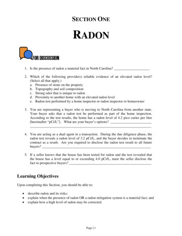
Standalone OperationPosition the Monitor1Place the radon monitor in the desired position in the area to be monitoredfor radon gas. The radon monitor does not need to be level.2To use a tripod, thread the standard tripod screw (1/4-20UNC) into thethreaded fitting on the bottom of the case (Figure 4).Figure 4. Using a TripodInstall a Fresh BatteryThe radon monitor can be operated on battery power or AC power. Whenconnected to AC power, the battery provides back-up power. However, evenwhen operating on AC power, a battery must be installed to provide backuppower.WARNING: Always install a fresh 9V battery before test or storage,even when the unit is connected to AC power, to prevent the internal3V battery from discharging. The 3V battery will discharge in 15 minutes; the battery is not user-serviceable and if discharged, the unitmust be returned to Sun Nuclear for replacement.With the radon monitor disconnected from AC power, a fresh alkaline battery willoperate the device for about 100 hours, or a fresh lithium-ion battery for about300 hours.5
CAUTION: High humidity may shorten battery life. Connect the ACpower adapter when using the radon monitor in areas with highhumidity.The battery is located in a small compartment on the back of the radon monitor(Figure 5). To install a new battery, Replacing the 9V Battery, below. A replacement9V battery can be purchased from Sun Nuclear or any retail source.Figure 5. Inserting a BatteryReplacing the 9V BatteryWARNING: Always connect to AC power before replacing the 9Vbattery, to prevent the internal 3V battery (required for operation)from discharging.The internal 3V battery will discharge in 15 minutes and if discharged, the unitmust be returned to Sun Nuclear for replacement. Additionally, if the 3V internalbattery is discharged, the time and date may be reset and the “Current” valuesmay be permanently erased.CAUTION: Never replace the battery during a test.1If a test is in progress, wait for the test to complete.2Connect the radon monitor to AC power using the AC adapter. SeeConnecting the AC Adapter on page 7.3Open the battery compartment door (Figure 5) on the rear panel of the unit.4Remove the old battery and unsnap the connector.6
5Connect a fresh 9V battery to the connector, insert the battery into thebattery compartment, and close the battery compartment door.Connecting the AC Adapter1After verifying a battery is installed (see Figure 5 on page 6), connect thepower cable to the power connector on the rear panel of the radon monitor.Figure 6. Connecting Power to the Radon Monitor2Plug one end of the power cord into the adapter and the other end into a 100to 240 VAC, 1-phase, 50-60 Hz mains power source.Turn on the DisplayTo conserve power, the 16-digit display is always off until the ON button ispressed. If no buttons are pressed for 2 – 3 minutes, the display turns offautomatically.To turn the display on:1Press the ON button (5). After a few seconds, the display turns on and showsthe message “Battery OK” (Figure 7).2If a Personal Identification Number (PIN) is set up, the display prompts theuser to enter it. The company name is displayed momentarily (if set up)followed by the message “Checking Memory.” If there is data in memory, themessage “Data in Memory!” appears. The data can be printed beforeclearing the memory.7
Figure 7. Turning on the Display3When the display shows “Start Test 5,” the user may start a new test,check AVG, check CUR, check STATUS, or change SETUP. The table belowsummarizes the steps to turn on the display.Press * Display Shows –nnnn––CommentBattery OKDisplay is always off until ON key (5) is pressed. “Battery OK” means there is enough power for 60 hours ofoperation (delay plus test). “Low/No Battery!” meansthat the battery has less than 60 hours operating life, orthere is no battery installed.Enter PINOnly appears if a Personal Identification Number hasbeen set up.NNNNEnter PIN using digits 1 – 4 (5 and 6 not supported;there are no buttons for 7 – 9). Numbers entered aredisplayed. Enter “5' after entering PIN.Company NamePress PIN button (5). If correct PIN was entered, company name (if set up) displays. If wrong PIN wasentered, message “Shutting down.” appears brieflyand then display turns off.CheckingMemoryIf data is in memory, the messages “Data in Memory!”and “Print and Clear” are displayed. Print and Clear thememory before starting a new test. See Clearing Memory on page 11.Start Test 5With the display reading “Start Test 5,” the user canpress a button to: Start a test. See Starting a Test on page 9. Check AVG or CUR. See Displaying Average and Current on page 10. Check STATUS. See Checking Unit Status onpage 11. SETUP the unit. See Setting Up Parameters onpage 12.After a few minutes of inactivity, the display turns offautomatically to save power.8
Starting a TestWhen the “Start Test 5” prompt appears, press the 5 button to start a new test.Press Display Shows CommentStart Test 5A new test can be started.Checking MemoryMemory is rechecked. If data is found, memorymust be cleared before starting a new test. SeeClearing Memory on page 11.–Delay0 hrDisplays the time delay defined in Setup.–Interval1 hrDisplays the measurement interval defined inSetup.–Duration12 hr–Test in Progress–Displays the test duration defined in Setup.The test has started and will be finished after theduration defined in Setup (plus delay). The displayturns off after a few minutes and remains off untilthe test is interrupted or the display is turned on.Interrupting a TestA test in progress can be interrupted to view the average or current readings.After the interruption, the test can be terminated or continued.Press –nnnnDisplay Shows CommentBattery OKDisplay turns on and battery is checked.Enter PINThis prompt only appears if a Personal IdentificationNumber was set up.NNNNEnter the PIN using only digits 1 through 4.NNNNPIN number is displayed. Press PIN button (5) tocheck PIN. If the wrong PIN is entered, the message “Shutting down.” is displayed.Press 5 to end a test prematurely or 2 to continue.Pressing 2 will turn off the display and continue thetest.––End Test Y 5 N 2Note, when this message is displayed, the useralso has the option to press AVG (3) or CUR (4) todisplay the average or current readings. See AVG orCUR During a Test, below.ConfirmPress 5 to confirm or 2 to cancel.Y 5 N 2Test CompleteThe test is terminated.Start Test 5A new test may be started. If there is partial testdata in memory, it must be cleared before startinga new test. See Clearing Memory on page 11.9
Note: A completed test cannot be interrupted. After a test iscompleted, pressing ON displays the normal start sequence.Displaying Average and CurrentNote: AVG is the average radon concentration over the totalmonitoring period; CUR is the average radon concentration over thelast 12-hour period.AVG or CUR During a TestThe average (AVG) or current (CUR) radon values can be displayed during a test.Turn ON the display (see Interrupting a Test on page 9), and note the button pressoptions in the table below.Press Display Shows Comment–End Test Y 5 N 2When the display shows this message, pressAVG (3) or CUR (4) to access those functions.orHold 3&4 Prt/ClrThis message only appears for a moment afterpressing 3 or 4. If the test was just started, themessage “Not Enough Data” is displayed.–Average1.2If AVG (3) was pressed, radon monitor displaysthe average radon concentration over the totalmonitoring period.–Current1.2If CUR (4) was pressed, radon monitor displaysthe radon concentration in the current 12-hourperiod.–Shutting down.After displaying AVG or CUR, monitor shutsdown to resume test.AVG or CUR After TestThe average (AVG) and current (CUR) radon values can also be displayed after atest is completed. Turn ON the display (see Turn on the Display on page 7), andnote the button press options in the table below.Press –Display Shows CommentStart Test 5Press AVG (3) or CUR (4).Hold 3&4 Prt/ClrThis message only appears for a moment afterpressing AVG (3).Average1.2Displays the average radon concentration overthe total monitoring period.Hold 3&4 Prt/ClrThis message only appears for a moment afterpressing CUR (4).10
Press Display Shows –Current–Start Test 51.2CommentDisplays the radon concentration in the current12-hour period.AVG or CUR reading is complete. The data for thetest remains in memory and must be clearedbefore starting a new test. See Starting a Test onpage 9.Clearing MemoryAfter printing the report, clear the memory using the key press options in thetable below.Press Display Shows Comment–Start Test 5It is recommended to print a report before clearing data. Prt 3 Cl 4 Ex 5When the “Start Test 5” message appears,press and hold 3 and 4. Keep holding until the“Prt 3 Cl 4 Ex 5” message appears. Press 4 toclear (or 5 to exit).ConfirmPress 5 to confirm the clear memory command.Y 5 N 2Clearing MemoryThe memory is cleared in a few seconds.Checking Unit StatusBefore starting a new test, it is recommended to scroll through the status itemsto confirm they are correct.Press –Display Shows CommentStart Test 5The status menu can be selected when the displayshows “Start Test 5.”Status MenuPress the (1) button to select the status menu. Thestatus of each item will scroll through automatically. Each item displays for about 2 seconds.–DELAYnn hrThe delay time selected.–INTERVALnn hrThe measurement interval selected.–DURATIONnnn hr–BATTERY–TIMEnn:nn PMCurrent time.–DATEMM DD YYCurrent date–CAL–SNC MODELOkMM/DD/YYYY1028The duration of the test.Battery status.Date of last calibration.Model number.11
Press Display Shows –CODE VER–S/N–Status Menu DonennnnnnnnnnnnnnnCommentEmbedded code (firmware) version number.Serial number.End of the menu. Display returns to “Start Test 5”.Status items can also be displayed during a test by pressing the (1) button whilethe display shows “End Test Y 5 N 2.”Setting Up ParametersNote: If there is any test data in the radon monitor, parameters cannotbe entered. Clear test data before changing parameters.Parameter data can be entered using a computer or by entering the characterswith the front panel keys on the radon monitor. Using a computer is the faster ofthe two methods. For instructions to enter parameter data using a computer, seeMonitor Settings Preferences on page 38. The table below shows the parameterkey press options.Press Display Shows CommentStart Test 5Parameters can be changed at any time beforestarting a test.Setup MenuEntering setup menu.–Checking MemoryChecking memory for data.–Delay–0.0 hr Shows current delay settings.Press arrow buttons to change value. If the monitor firmware version is 106 or higher,the delay options are 0.0 hours,12 hours, 24hours, or 48 hours. If the monitor firmware version is 105 or lower,the delay options are 0.0 hours or 12 hours.orDelay12 hr For the steps to check firmware version on astandalone monitor (not connected to a computer), see Checking Unit Status on page 11. Forthe steps to check the firmware version from thecomputer, see Monitor Settings Preferences onpage 38. The serial number and firmware versionof the unit are displayed on the right side of theMonitor Settings screen.IntervalSAVE; saves the Delay setting and1.0 hr Pressadvances to Interval.Interval4.0 hr intervals, 0.5 (model 1029 only), 11.0, 2.0, 4.0, 8.0,Press arrow keys to scroll through selection ofor12,16, 20, or 24 hours.12
Press orDisplay Shows CommentDuration 1.0 hrPress SAVE; saves the setting and advances tothe next item.DurationPress arrow keys to scroll through test durationtimes: 1.0, 12, 24, 36, 48, 60, 72, 84, 96, 100, or999 hours.If 999 is selected, measures until memory is full orto 720 data points, whichever occurs first.48 hrCOMPANY CompanyPress SAVE; saves the setting and advances tothe next.COMPANY CompanyThe EDIT key (3) lets you begin to edit the firstcharacter.COMPANY MompanyPress the arrow keys to scroll through the available characters. See Character Set on page 14 fora list of characters. Press and hold for rapid scroll.COMPANY My CompPress EDIT key (3) and scroll to the next and subsequent characters. Press EDIT (3) again to enterthe next character. Continue character by character until the company name is entered (up to 30characters).ADDRESS1 nonePress SAVE (4); saves the setting and advances tothe next item.ADDRESS1 9oneThe EDIT key (3) allows editing beginning with thefirst character. Enter up to 30 characters for thefirst address line using the same procedure as forCompany name.ADDRESS2 nonePress SAVE (4); saves the setting and advances tothe next item.ADDRESS2 noneIf a second address line is not needed, leave itblank. The EDIT key (3) will allow editing beginning with the first character. Enter up to 30characters for the second address line using thesame procedure as for Company name.CitynonePress SAVE (4); saves the setting and advances tothe next item.andCitynoneEnter city (20 characters) and SAVE (4) (same asabove).andSTATEnoneEnter state (10 characters) and SAVE (4) (same asabove).andZIPCODEEnter zip code (10 characters) and SAVE (4) (sameas above).andPHONEEnter phone number (20 characters) and SAVE (4)(same as above).andLICENSEEnter license number (10 characters) and SAVE (4)(same as above).andTIMEEnter current time (4 numbers plus AM or PM)and SAVE (4) (same as above).andDATEEnter current date in the format MMDDYY (6numbers) and SAVE (4) (same as above).or13
Press Display Shows pC/lCommentSelect units, pCi/l or Bq/m3 (edit, select witharrows, and SAVE (4)).andUNITSandPIN NUM 1111Enter a PIN number if desired in the range of 1111to 4444 and SAVE. The number 1111 is equivalentto no PIN. To clear a PIN, enter 1111.Setup Menu DoneEnd of setup menu.To enter parameter data using the front panel keys on the radon monitor:1Turn on unit.2Press “Setup” (button 2).3Advance through the list by pressing “Save” (4).4Stop on an item to change it.5Press “Edit” (3) to edit the item.6Press the arrow keys to scroll through a list of available characters and stopwhen the desired character appears. Press and hold arrow key for fast scroll.7When a desired character to change appears, press “Edit” (3) again tochange it.8When all the characters are changed, press “Edit” to complete the item.9Press “Save” and advance to the next item.Character SetThe available character set includes the following in the sequence shown:(space) ! “ # % & ‘ ( ) * , - . / 0 1 2 3 4 5 6 7 8 9 : ; ? @ A B C D EFGHIJKLMNOPQRSTUVWXYZ[\] ‘abcdefghijklmnopqrstubwxyzDisplay Turns Off AutomaticallyThe display turns off automatically after a period of inactivity of about 2-3minutes. There is no OFF switch or key sequence.14
Clearing a Reset1Turn on the radon monitor to check the battery. If the system is accidentallyreset, clear the reset as shown in the table below.Press Display Shows BatteryOKCommentBattery is checked.–System has resetSystem has been reset.–Check Date/TimeAn alert to check the date and time and re-enterthem.Clear Reset? Y 5Sets the system back to operational mode.Shutting down.System shuts down.–2Start the radon monitor again. See Turn on the Display on page 7.3In Setup, change the date and time. See Setting Up Parameters on page 12.Note: A reset does not clear or change any test data stored in memory.Low Battery MessagesA 9V battery must always be installed, even when using an AC power supply, toprevent discharge of the internal 3V battery. When the battery is low or needs tobe replaced, a message is displayed on the radon monitor. The following sectionsdescribe the messages that may be displayed.Low Battery with AC Power ConnectedIf the battery is low and the AC power adapter is connected, a message appearswhen key 5 is pressed.Press Display Shows CommentLow/No Battery!Battery is checked. Does not have enough powerfor a 60-hour test.–Replace Battery!Replace the 9V alkaline battery as soon as convenient. Current test can continue until complete if ACpower is reliable.–Shutting down.The system shuts down to save power.Replace the 9V battery as soon as the test is complete. See Replacing the 9VBattery on page 6.15
Low Battery Without AC Power ConnectedIf the battery is low and the AC power adapter is not connected, a messageappears when attempting to power on.Press Display Shows CommentLow Battery!Battery is checked. Does not have enough powerfor a 60-hour test.–No Extern. PowerIndicates AC power should be connected to continue the test in progress. At the conclusion of thetest, replace the battery.–Shutting down.The display shuts down to save power.Connect the AC adapter to continue the test or perform any other operation.Replace the 9V battery as soon as possible. See Replacing the 9V Battery onpage 6.Storage Under PowerWARNING: For long term storage, always connect to AC power orinstall a fresh 9V battery to prevent the internal 3V battery (requiredfor operation) from discharging. The 3V battery is not user-serviceable and if discharged, the device must be returned to Sun Nuclearfor replacement.The radon monitor must always be stored with a 9V battery installed or connectedto AC power. This additional power is required to prevent discharge of the 3Vlithium battery located inside the unit. The 3V battery will discharge in 15 minutes,and if the internal battery is discharged, it must be replaced at the factory. SeeContacting Sun Nuclear Support on page 54.16
Portable Printer (Optional)Printer - PartsThe following parts are included with the optional portable printer, P/N 1028050.Part NumberDescription022005ZPower supply, 6 VDC out, 2.1 mm plug750052Rechargeable battery pack, 4.8 V Ni-MH801008ZLine power cord for printer, detachable, IEC Plug to USA style,125 V, 10 A, 2.3 m.801032ZCable, RS-232 (serial), DB9M to DB9F, 6 ft.850040ZThermal printer850043ZThermal printer paper (roll)Printer - DescriptionThe optional portable printer pri
radon monitor to Sun Nuclear Corporation for annual re-calibration. No. Part Number Description 1 1028300 or 1028300-RM Model 1028 Radon Monitor* or Model 1028 Radon Monitor (Refurbished) 2 801041Z Cable, USB A-B M, 2 m 3 741011** Power supply, 18 VDC, 100-240 VAC, 0.3A