Transcription
4A-10Design BureauStorm Sewer DesignDesign ManualChapter 4DrainageOriginally Issued: 07-29-11Revised: 06-25-19GeneralThis section will assist in understanding the principles, assumptions, and design criteria required for stormsewer design to assist in computer modeling and checking.The Iowa DOT requires computerized modeling design using Geopak Drainage.Design in Geopak Drainage is desired for many reasons including: Uniform use of design drainage library components. Facilitation of running and evaluating alternate design storms, scenarios, and criteria. Evaluation of flow regimes. Hand calculations generally ignore or do not adequately evaluatejunction losses at structures and/or velocity changes within pipes. Not all flows are subcritical,steady, uniform, etc. Models can help determine where flow regimes may be critical. Evaluation of the hydraulic grade line (HGL) and tailwater conditions that are related to theprevious bullet item as well as other constraints. Facilitation in plan preparation and reporting.CADD: See Sections 4A-55 and 4A-57 for instructions on adding pipes and drawing pipe profiles.Excel spreadsheets and hand calculations are useful for design checks; however, due to the variousscenarios and flows required to be evaluated and the need to evaluate the HGL, spreadsheets and handcalculations should not be used as design tools.Storm sewer systems are designed after intake types, locations, and sizes have been identified. Thedesigner should consider such items as roadway classification, design traffic, cost, and safety (risk) in thedesign analysis. Placement and discharges of storm sewers should be designed to take intoconsideration potential damage to adjacent and downstream properties.Before beginning storm sewer design: Verify maximum structure spacings are not exceeded. Refer to Section 4A-4 for requirements. Fully understand concerns and issues related to redirecting flow (taking flow – including theconsideration of bypass flow – from one drainage basin to another,) or discharge to undefineddrainage ways. Document reasons for doing so along with design considerations. Determine downstream controlling conditions including: Outfall Conditions, Tailwater Conditions,Downstream Erosion Potential and Runoff Reduction. Determine the existing and desired maximum high water elevation (HWE) at critical locationswithin the system. These locations may include intakes, or anyplace where there is access to thesystem. The design maximum HWE should not interfere with the intended function of anyopening nor should it reach a manhole cover.For pipes under railroads, contact Iowa DOT Office of Rail Transportation.For footing drains or other urban connections to the storm sewer system, refer to SUDAS design criteria.Page 1 of 10
Chapter 4—DrainageSection 4A-10—Storm Sewer DesignA section of storm sewer connecting one intake or manhole to another is often called a “run” or “link”. Astorm sewer system is designed from run to run. Design generally begins at the upstream end (or reach)of the system and proceeds down to the outlet. The process for determining the HGL begins at the outletand works upstream. Downstream tailwater conditions – the water surface elevation of the receivingchannel – may affect the design as well. Thus the overall design process is often iterative.Hydraulic design of storm sewer systems requires an understanding of basichydrologic and hydraulic concepts and principles. Refer to HEC-22 Chapters 3 and5 for a review of some basic hydraulic principles. This section assumes a basicunderstanding of these principles.Design of storm sewer systems generally assumes open channel flow for the minor storm event. Tomaintain open channel flow, the system must be sized so that the water surface remains open toatmospheric pressure (i. e. the flow depth is less than the pipe diameter). For this to happen, the HGLmust be contained within the pipe. Consideration of pressure flow is allowed for the major storm event.In pressure flow, the hydraulic grade line will be higher than the pipe diameter.Simple storm sewer design involves several assumptions such as steady and uniform gravity flow,junction losses in intakes and manholes, outlet conditions, etc. Equations and methods used for designare empirical and contain coefficients and assumptions. Existing systems should be investigated,evaluated, modeled, and calibrated before upgrading them or adding to them. An evaluation of theexisting system profile along with an understanding of existing drainage concerns will assist in estimatingthe desired modeling extents. Design work and/or modeling may result in the determination of additionaldesign/modeling needs.Storm drains are expensive and permanent elements that are often very costly to replace, especially ifreplacement affects pavement, intakes, or other infrastructure. At a minimum, design models should bechecked and verified by an individual experienced with storm sewer drainage design. When possible,alternate methods or models should be used to check designs. When results differ significantly betweenmethods or models (more than 5 to 10 percent), the methods or models should be investigated todetermine what may be causing the differences and why.Complex designs including but not limited to: detention basins, pump stations,complex networks, and/or systems with notable drainage concerns may requiredynamic hydrograph routing computer modeling. Methods used for Dynamicmodeling are to be approved by the Department for the specific project or task.The remainder of this section discusses the following: Design Criteria Outfall Conditions Tailwater Conditions Downstream Erosion Potential and Runoff Reduction Hydraulic Grade Line Pressure Flow Design Check for Major Storms Intake and Manhole Sizing Filling in Tabulation 104-5B Design Documentation and ReportingDesign CriteriaDesign criteria are summarized below with more in-depth discussion following. Location and Horizontal Alignment: Refer to discussion.Page 2 of 10
Chapter 4—DrainageSection 4A-10—Storm Sewer Design Type of Pipe: Assume concrete pipe with a Manning’s n 0.013. Minimum Pipe Size: 15 inch diameter. 24 inch diameter under Interstate pavement. Minimum Cover: Refer to discussion. Minimum Vertical Drop at Structures:oEqual pipe sizes: 0.3 feet is preferred, but 0.1 feet is allowed.oChanging pipe sizes: match soffit elevations. Minimum Pipe Grades: For construction purposes, a slope greater than 0.4% is preferred. Initialestimates may use the average slope of the ground. Use 1% minimum grade for cross runs andstubs. Pipe Flow oAssume 100% intake capture. Add possible bypass flow from other systems and off-sitelocations.oMinor Storm: Flow remains within pipe.oMajor Storm: Pressure flow allowed if hydraulic grade line remains below intakes andmanhole lids.oPipe Friction Loss: Use 0.013 for Manning’s n for concrete pipe. Follow jurisdictionalrequirements for other pipe types.Design VelocityooWithin pipe system: Minimum: 3 fps for cleaning velocity using a 5 year (Q5) recurrence interval. Maximum: 15 fps calculated at the minor storm event and evaluated at the major storm.Maximum Outfall Velocity: Refer to discussion. HGL: Refer to discussion. Crossings and Clearances (clearance is defined as outside of pipe to outside of pipe):oFrom Sanitary Sewer Mains: Minimum horizontal clearance is 5 feet. Minimum crossingvertical clearance is 6 inches with special structural support required at less than 18 inches.Clearance is defined as outside of pipe to outside of pipe.oFrom Water mains: Minimum horizontal clearance is 10 feet. Minimum crossing verticalclearance is 18 inches. Location and Horizontal AlignmentDesign and place storm sewer with straight alignments between structures.Parallel to street: Place storm sewer behind the curb as much as practical.Transverse: Connect each end with to intake, manhole, or outfall.Place public storm sewer systems located outside of the State right-of-way (ROW) in a storm sewereasement. Storm sewer easements should have a minimum width of 20 feet or two times the depthof the sewer (measured to bottom of trench), whichever is greater. The storm sewer should becentered in the easement. Additional width may be required by the Jurisdictional Engineer formaintenance purposes. Consideration needs to be given to future pipe repairs when consideringeasement locations and widths.Where street layouts are curved with a radius of curvature greater than 200 feet and the storm seweris 48 inches in diameter or greater, consideration may be made for a curved sewer using factoryfabricated pipe bends. Consideration needs to be made for cost, available standard long radius curvesizes, and pipe industry recommended maximum deflection angle.Refer to the SW Series of the Standard Road Plans for location stations of intakes and manholes.Page 3 of 10
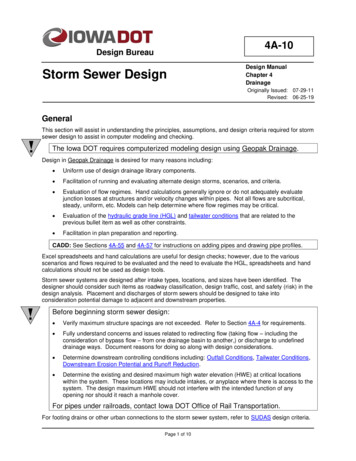
Chapter 4—DrainageSection 4A-10—Storm Sewer DesignType of PipeDesign assuming concrete pipe. Concrete pipe is required under the pavement for all Primary andInterstate Highways, except non-NHS highways where ADT is less than 3,000. Assume a Manning’sroughness coefficient n 0.013. Use the strength (class) and wall type required by the StandardSpecifications and Standard Road Plans. The designer should evaluate the application with respectto the design fill height, ground water table, and other standard design considerations. Designexamples in this section are based on concrete pipe. When a local jurisdiction allows another type ofpipe outside of Primary Highway pavement, use SUDAS design criteria for the alternate pipe.For trenchless installation, refer to Section 2553 of the Standard Specifications. For footing draindesign considerations, refer to SUDAS for design criteria.Minimum CoverUnder pavement: Top of pipe at least 1.0 foot below the bottom of subbase. If the pipe does notmeet this requirement, adjust it until it does, or provide a design method to maintain the integrity ofthe pipe and pavement. Special design may include consideration of higher classification of pipe withflowable mortar backfill or other design measures.Outside of pavement: 3.0 feet of cover is recommended. A minimum of 1.5 feet is required.Justification is required for less than 1.5 feet of cover.Note: Section 1B-5 provides pipe wall thicknesses to assist with the evaluation of minimumcover.Minimum Vertical Drop at StructuresThe flow line (invert elevation) of a pipe is located at the inside bottom of the pipe opening. The soffit(crown, overt) of a pipe is located at the inside top of the pipe.To avoid trapping water, the Flow Line In elevation of a pipe taking flow from a structure should belower than the flow lines of all upstream pipes entering the structure. Use the following criteria: When the outgoing and incoming pipes are the same diameter, drop the flow line 0.30 feetwhere possible. A drop of 0.10 feet is allowed where 0.30 feet cannot be achieved. When the diameter of the outgoing pipe is larger than the incoming pipes, align the soffits ofthe pipes. Where there are more than two inlets, generally the elevation of the soffit of thepipe leaving the structure will be aligned with the soffit of the largest pipe entering thestructure.These are the minimum elevation drops. On steeper grades, it may be necessary to make elevationdrops larger in order to reduce the slope and keep water velocity under the scour velocity (15 ft/sec).Minimum Pipe SlopesPipe velocity sets minimum slopes for storm sewer. However, for construction purposes, a slopegreater than 0.4% is preferred. Initial estimates may use the average slope of the ground unless thiswould be unreasonable (such as in bluff areas). Use 1% minimum slope for cross runs and stubs.Steep grades may result in flow transitioning from subcritical (tranquil) to supercritical (rapid) within apipe, greatly affecting the velocity in the pipe. Caution and hydraulic understanding are requiredwhen working with pipes on steep grades. Computer modeling may assist in determining hydraulicissues and concerns.Pipe slope is calculated using the difference between the inlet and outlet flowline elevations dividedby the horizontal distance measured from inside wall of the upstream structure to inside wall of thedownstream structure. The actual required length of a pipe for construction is calculated along theslope of the pipe. To make measurement easier for payment purposes, the Department measuresalong the ground from center of structure to center of structure. Therefore, the measured paymentlength is often different from the required installation length. The designer should ensure that pipelengths used in the design provide the appropriate pipe design slope value, which in turn is used todetermine the pipe design velocity and capacity.Page 4 of 10
Chapter 4—DrainageSection 4A-10—Storm Sewer DesignPipe FlowMaximum pipe flow capacity occurs at approximately 93% of the height of the pipe. This means thatif the pipe is designed for full flow, the design will be slightly conservative. Pipe sizing should assume100% capture at intakes. Do not decrease the size of pipe in the downstream direction, except forspecial situations such as detention or retention facilities. Geopak Drainage can help withdetermining initial pipe size estimates. Simple calculations may also be run using the procedurediscussed in Sizing Pipes below.As part of the storm sewer sizing analysis, evaluate bypass flow to other systems and impacts tothose systems. When evaluating a portion of a system, be sure to include the flow contribution fromthe upstream watershed.Special consideration may be required for pipes at sag locations. Sag intakes are designedassuming no plugging. Flanking intakes are added after the intake design is completed. Thereforethe intake design analysis basically assumes no flow to the flanking intakes. For pipe design, thedesigner needs to assume the sag intake is completely plugged and 50% of its flow is captured ineach of the two flanking intakes. Piping from flanking intakes should accommodate 100% of the flowto that intake plus 50% of any additional flow between that intake and the sag intake. This designrequires inputting different design values into GEOPAK drainage to evaluate the different intake andpipe scenarios.Design pipes connecting flanking intakes and sag intakes assuming 50% of the flowto the sag intake is captured at each flanking intake (i.e. assume the sag intake iscompletely plugged).Sizing PipesPipes are often evaluated using Manning’s Equation modified for circular pipes:2.67 K DQfull π u 1.67 S n 4 (Equation 4A-10 1)where:Qfull Circular pipe full flow capacity, ft3/s.S Slope, ft/ft.n Manning’s roughness coefficient, Use 0.013 for concrete pipe.Ku Units conversion factor, 1.49.D Inside diameter of pipe, ft.Note: Full flow capacity is the capacity exactly at the point when the pipe begins to run full, butbefore pressure flow begins. It does not include pressure flow which also generally has pipes flowingfull.This equation does not account for things such as inlet or outlet control, pressure flow, special flowconditions, etc. The user should be familiar with the limitations of its use. For other pipe shapes referto HEC-22.To use Equation 4A-10 1:1. Assume a pipe diameter and slope (or check an existing pipe)2. Solve for Qfull, which is the estimated capacity of this pipe at full flow.3. If Qfull is less than the design Q, adjust the slope, pipe size, or both until Q full is greater thanthe design Q.Because Equation 4A-10 1 has three independent variables (slope, diameter, flow), two of thesevariables may be known or assumed to solve for the third. Solving for D the equation becomes:Page 5 of 10
Chapter 4—DrainageSection 4A-10—Storm Sewer DesignD 0.263 (Q0.3750.1875 )SEquation 4A-10 2Where Q may be the design flow and D and S are the same as in Equation 4A-10 1. To useEquation 4A-10-2:1. Solve for D using the design flow and assumed or known slope.2. Round the answer up to the next standard pipe size.Note: Adjustments to the size of pipe or slope must maintain the velocity within acceptableparameters.Design VelocityA self-cleaning velocity should be maintained to reduce the buildup of sediment that may lead to lossof capacity. For this reason, storm sewer systems are designed to maintain a minimum velocity of 3ft/s or greater. This should be checked using a 5-year recurrence interval. This is most readilyverified using computer modeling. In addition it is desirable to reduce junction losses and minimizeflow transitions between subcritical and supercritical, which is why there is a maximum velocity valuewithin systems (this is different than the maximum desired velocity at the outfall).At the outlet: With a flared end (apron) section: Maximum of 5 ft/s and evaluate downstream scourpotential to determine if energy dissipation and/or scour measures are required. With flared end section, footing and rip-rap, or other approved scour countermeasure:Maximum of 10 ft/s and evaluate downstream erosion potential. With energy dissipation device: Maximum of 15 ft/s and evaluate downstream erosionpotential.Equation 4A-10 3 can be used to determine full flow velocity in a circular pipe (assuming full, steady,uniform flow):Vfull Q full K D u A n 4 0.67S(Equation 4A-10 3)where:Vfull Velocity of full flow, ft/s.A End Area of pipe (πr2), ft2.Qfull, S, n, Ku, and D are the same as in Equation 4A-10 1.Partial pipe flow velocity can be much greater than the full pipe flow velocity, because at full flowthere is more pipe friction acting on the water, thus slowing it down. As discussed under pipe flow,full flow is not to be confused with pressure flow. Computer modeling is the most efficient method toevaluate pipe velocity and the impacts that slope and pipe diameter have on it. The Flow ElementsChart can be used (as discussed below) to evaluate or estimate partial flow velocities in pipes. Adjustthe diameter and slope until the partial flow velocity in the pipe falls between the minimum andmaximum values.Chart 4A-10 1, Flow Elements Chart1. Select a preliminary pipe size using known Qdesign.2. Assume a slope (generally begin with ground slope).3. Use Equation 4A-10 2 to solve for pipe diameter D.4. Select a standard pipe size greater or equal to D.5. Determine Qfull for the selected D.Page 6 of 10
Chapter 4—Drainage6. DetermineSection 4A-10—Storm Sewer DesignQ designQ full.4. Using the result from step 6, look upVdesignVfullin the Flow Elements Chart.5. Determine design flow velocity:Vdesign VdesignVfull VfullThe following example demonstrates the process.Example Problem 4A-10 1, Pipe Velocity and TimeTime in PipeTime in Pipe (Tpipe) is calculated as:Tpipe L60Vdesign(Equation 4A-10 4)where:Tpipe time in pipe, minutesL Pipe Length, ftVdesign Design Velocity, ft/sSection 4A-5 provides a worksheet and examples for calculating overland Tc.Example 4A-10 1, Pipe Velocity and TimeTime of Concentration (Tc) for pipe systems should consider and use the greater of: Tc for the upstream intake plus time in pipe. Tc for the intake.Example 4A-10 2, Evaluation of System Time of ConcentrationHGLThe HGL is a line coinciding with the water level in the system. For the minor storm, the HGL must be within the pipes. For the major storm, the HGL must be below intake form grade elevations and manhole lidelevations.Outfall ConditionsAll storm sewer systems have an outlet to which they discharge. The discharge point can be a naturalstream, a ditch, an existing storm sewer system or culvert, or a proposed channel or system. AASHTOcautions, “Outfalls are the most downstream element in the storm drain system but should not be the lastelement to receive design attention” (Highway Drainage Guidelines, 4 th Edition). The procedure forevaluating a storm sewer design begins at the outfall; therefore, consideration of outfall conditions is veryimportant to storm sewer design. The following outfall conditions should be determined for each outfallbefore beginning storm sewer design: Outfall location. The discharge location may be into a receiving stream or an existing stormsewer system (open channel or closed conduit). Refer to Section 4A-4 for the Concept Plan.Consult with a drainage engineer before planning to discharge to an undefined swale, ditch, orstream.Page 7 of 10
Chapter 4—Drainage Section 4A-10—Storm Sewer DesignOutfall elevation. The storm sewer system outfall pipe flowline (also known as invert or insidebottom) elevation should not be below the receiving flowline elevation. For a receiving ditch orstream, the adjacent streambed flowline elevation should be evaluated for a determined distance(don’t just use existing survey data at the existing outfall) so that elevations in scour (erosion)holes are not used.See Design Velocity for additional design criteria.Once outfall conditions have been determined, tailwater conditions and downstream erosion potential canbe evaluated.Tailwater ConditionsThe design water surface elevation (design WSE) of the outfall is used in design to begin the HGLdetermination. The outfall design WSE must be estimated for the normal operating conditions of thestorm sewer system and for alternate scenarios to assess risk of ponding or flooding potential.Determination of the design WSE and alternate scenarios requires knowledge of the outfall systemwatershed, storm sewer system watershed, and other factors and should be evaluated by someoneknowledgeable in this design. Refer to AASHTO Highway Drainage Guidelines, 4 th Edition, Chapter 9 forfurther consideration.Downstream Erosion Potential and Runoff ReductionHEC-14 notes, “Erosion at culvert outlets is a common condition. Determination of the local scourpotential and channel erodibility should be standard procedure ” Discharge velocities are the mainindicator of erosion potential and may be minimized by upstream storm sewer design considerations.Existing downstream erosion and/or flooding problems should be documented and evaluated.Stormwater storage and/or energy dissipation may be required to protect an outfall, storm drain outlet,and/or downstream channel or property (including stream banks). Designers should evaluate existingconcerns and other erosion indicators such as soil type, increase in discharge flow or volume over naturalundeveloped discharges, etc.HEC-14 discusses hydraulic design and energy dissipaters for culverts and channels. It also discussesflow transitions from pipe through flared end sections (aprons) and into channels. Chapter 5 of HEC-22discusses stable channel design procedures and provides example problems for design and evaluation.Refer to Section 4A-2 and Section 4A-4 for additional discussion on concept design considerations anddocumenting erosion potential and runoff reduction. Refer to SUDAS for erosion control and detentionguidelines.Hydraulic Grade Line (HGL)The HGL is a line coinciding with the water level in the system. It is used to determine the acceptability ofa design, see HGL under Design Criteria. Computer modeling is ideal for HGL checks. For handcalculation checks, refer to Chapter 7 of HEC-22 for step by step guidance on estimating the HGL and fordesign examples.Note: Ideally, the HGL throughout the storm sewer should maintain a smooth slope and stablevelocity. Avoid abrupt jumps in the HGL.Pressure Flow DesignPressure flow design requires that the flow in the pipe be at a pressure greater than atmosphericpressure. Under this condition the water surface in the structures (intakes and manholes) is above the topof the pipes. The significant difference between pressure flow and open channel flow is that the pressurehead will be above the top of the pipe and will not equal the depth of flow in the pipe. In this case, thepressure head rises to a level represented by the HGL.The hydraulic gradient can be roughly estimated using the following formula:Page 8 of 10
Chapter 4—DrainageSection 4A-10—Storm Sewer DesignHydraulic Gradient elevationupstream - elevationdownstreamlengthwhere:elevationupstream may be ground surface or top of pipe, ftelevationdownstream generally the receiving stream or system WSE, ftLength length between above elevation locations, ftThe hydraulic gradient may be checked across several pipes and structures (length may include severalpipes and structures). This evaluation may be used for rough evaluation of existing systems, conceptdesigns and for rough design checks. Use computer modeling to evaluate the HGL of a system for finaldesign purposes.The following two example problems illustrate the hydraulic gradient design check.Example 4A-10 4, Pressure Flow Problem 1Example 4A-10 5, Pressure Flow Problem 2Check for Major StormsOne of the last procedures in designing a storm sewer system is evaluation of and design for the majorstorm check. This generally includes design for the 100-year storm with consideration of overland flowpaths for greater events. The major storm check is dominated by three concerns: Ponding depth on primary highways is not to exceed 1 foot. Residential dwellings and public, commercial, or industrial buildings are not to be inundated at theground line unless they are flood-proofed. Water is not to accumulate in areas where it creates an unacceptable safety hazard for motoristsor pedestrians.To avoid these situations, drainage structures may need to be installed that do not correspond to thenormal design recurrence interval.When examining the system for a major storm event, determine how excess water will be stored and howit will reach the outlet (e.g. stream, river, lake). When excess water cannot get into the storm sewersystem, the individual intakes – or possibly the entire storm sewer system – must be resized. Designersmust consider all overland flow paths the water may take during the major design storm and greaterdesign events. Flowage easements may be required to maintain overland flow paths and to preventconstruction and building in overland flowage areas. Evaluation of major storms and the need foroverland flowage easements requires careful analysis due to the potential impact on surroundingproperty.Intake and Manhole SizingOnce storm sewer pipes are sized, intake and manhole sizing can be finalized. Refer to the StandardRoad Plans for intake and manhole dimensions.The placement and type of manhole depends on: Location of traffic. Depth of manhole. Size of intercepting storm sewer pipe(s). Skew of intercepting storm sewer pipe(s). Other utilities.Note: Scale drawings of pipes at structures will assist in evaluating structure dimensions (both verticallyand horizontally).Page 9 of 10
Chapter 4—DrainageSection 4A-10—Storm Sewer DesignCircular StructuresPrecast manholes come in standard sizes. For each installation, a minimum diameter is required tomaintain the structural integrity. The general rule is to keep a minimum of 6 inches betweenblockouts for adjacent pipes. To evaluate this, the blockout sizes of and angles between adjacentpipes are required. Refer to Table 1 for standard blockout dimensions.Table 1: Manhole Blockout Sizes1.1pipe diameter(inches)151821242730333642485460Based on RCP.manhole blockout(inches)242831353842474857647178When two or more pipes are involved, adjacent pipes involving the most critical situation (the smallestangle and largest pipes) should be evaluated. If the critical situation is not apparent, then evaluate allsituations involving adjacent pipes.Rectangular StructuresStandard rectangular structures do not accommodate all pipe sizes. Larger pipe sizes may requireintake modification.Most intake and manhole standards provide guidance on maximum depths. Table 2 providesguidance for those which do not.Table 2: Intake Maximum Depths.intake typeSW-501SW-505SW-506SW-511maximum depth (ft)776.57Filling in Tabulation 104-5BUse output from Geopak Drainage to fill out Tabulation 104-5B for the Plans.When using letdown structures, calculate the exact length of pipe required for installation and adjust forelbows. Adjust flow lines accordingly. Round measurements to the next higher whole foot. If two typesof pipe are used on the same structure, tabulate them on separate lines of the bid tabulation.Design Documentation and ReportingStorm sewer system documentation and reporting is discussed in Section 4A-2. Designers should alsoinclude an analysis of HGL results.Page 10 of 10
Chronology of Changes to Design Manual Section:004A-010 Storm Sewer Design6/25/2019RevisedUpdated hyperlinks.Updated header logo and text.2/9/2017RevisedRemoved metric units from the section.Added reference to Section 1B-5 for pipe wall thicknesses.9/13/2012RevisedUpdated minimum cover outside of pavement to match SUDAS.7/29/2011NEWRewritten material from old 4A-8. Removed example problem.
The flow line (invert elevation) of a pipe is located at the inside bottom of the pipe opening. The soffit (crown, overt) of a pipe is located at the inside top of the pipe. To avoid trapping water, the Flow Line In elevation of a pipe taking flow from a structure should be lower than the flow lines of all upstream pipes entering the structure.