Transcription
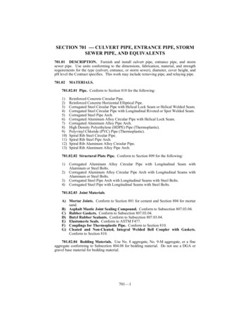
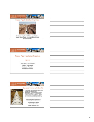
Proper Pipe Installation PracticesUnderstanding the installation, specification,design requirements and material differencesfor pipe systemsProper Pipe Installation PracticesAgendaBasic Pipe & Soil ConceptsTrench FundamentalsInstallation ProcedureBackfill Testing RatesExpected Service Life/Benefits A well installed pipe should stay in service 50 to100 years with little or no repair.DelDOT states 75 years for higher functionalclassification roads (SLI), 50 years for lowerfunctional classification roads (SLII), 25 yearsfor commercial/multi-family entrances (SLIII)and 15 years for residential entrances (SLIV).PROPER INSTALLATION BENEFITS Essential to Pavement Performance Increases Bearing Capacity Increases Service Life Lowers Maintenance Cost1
Fundamentals and Installation of Drainage PipeFactors Contributing to Successful Performance1. Hydraulic Characteristics and Capacity2. Structural Capacity(Cover, Loads)3. Environment Conditions(pH of soil and water)(Soil Resistivity)(Abrasion due to sand and/or gravel)(Standing Water)PIPE TERMINOLOGY(RCP)(Metal, HDPE and RCP)What 2 functions must an underground pipe provide?ConduitStructure2
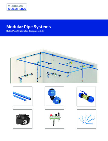
Reinforced Concrete Pipe Structural System– RCP Pipe Wall Majority of Strength 60% ‐ 90% of System Strength– Foundation & Bedding 10% ‐ 40% of System StrengthCoverPipe IDRigid PipeStructure56,000 lbs/ft/ftConduit42” Pipe (CL IV)Flexible Pipe Structural System Flexible Pipe Wall 5% - 10% of System Strength Foundation & Bedding Carries Majority of Load 90% - 95% of System StrengthCoverPipe ID3
Flexible InstallationConstruction Loading Culverts are generally designed for theloads they must carry afterconstruction is completed.Construction loads often exceeddesign loads. These heavy loads cancause considerable damage in flexiblepipes and can cause D-load crackingin rigid pipes.Additional temporary fill is needed toprotect the pipe from constructionloads.Construction Loading Culverts are generally designed for theloads they must carry after constructionis completed. Construction loads oftenexceed design loads. These heavyloads can cause considerable damagein flexible pipes and can cause D-loadcracking in rigid pipes.Additional temporary fill is needed toprotect the pipe from construction loads.4
Minimum CoverProper Cover?Pipe Installation/Construction ChecklistProper Installation Basic Requirements:Pipe Material in Good Condition from Delivery to FinalInstallationCompactionBackfill MaterialProper Installation ProceduresInspection During InstallationPost Installation Inspection per DelDOT Manual5
Verifying Pipe1.Metal PipeGauge: 12, 14, 16Corrugation: 2 2/3” x ½”; 3” x 1”2. Reinforced Concrete Pipe Class III, IV, or V3. HDPE Pipe Meets AASHTO Pipe Storage Out of the way Stacked and chocked Do not stack on bellsPipe Delivery/HandlingPipe DeliveryCommunicate with DispatcherProper Placement at SiteProtect People/Pipe (Safety)6
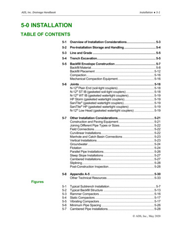
Pipe Delivery/HandlingNestedPipe HandlingNesting (Safety)Proper Sling PlacementProtect People/Pipe (Safety)Fundamentals and Installation of Drainage PipeTrench FundamentalsTrench TerminologyFinal BackfillVaries* Below roadway orshoulders95% or moremax. densitySpringlineBorrow Type Csubsection 209.04Bedding – 6” (min. loose Sand or type C Borrow)Foundation7
Trench/Pipe TerminologyFoundationTrench/Pipe TerminologyFoundationPipe Bedding/BackfillDelDOT8
Soil PropertiesWhat three major soil properties comeinto play when installing a pipeline?1. Composition2. Gradation3. CompactionComposition Soil is an aggregate of loose mineraland organic particles. Rock exhibits strong and permanentcohesive forces between mineralparticles. Soil’s primary components are: GravelSandSiltClayGradationWell-graded soil has all sizes of material present from the No. 4sieve to the No. 200 sieve.Well gradedPoorly graded soil may be uniformed-graded or gap-graded.Uniformly gradedGap graded9
Compaction Compaction is the densification of soil by the reduction of airin the soil voids. More difficult for water to migrate Reduce subsequent settling under loading The degree of compaction is measured in dry unit weight (drydensity). Increase shear strength of soilCompaction Factors That Affect Compaction: Water content of the soil Type of Soil Compactive effort lift thickness, number of roller passes, weight of theroller The type of compaction equipment smooth drum, sheepsfoot, pneumatic tire, vibratingplate, vibratory or static, etc The speed of application Compactive energyFundamentals and Installation of Drainage PipeInstallation Procedures10
Installation Methods - re is NO Perfect Pipe All pipes bring certain strengths and weaknesses. Good designers/installers must accommodate for strengths that best benefitthe project, while making sure the weaknesses don’t jump up and bite you.Installation is Key Careful attention to construction details such as pipe bedding, backfillmaterial, compaction and trench width are vital. Poor compaction or poor quality backfill around culverts will result in unevensettlement and structural distress of the culvert which directly effects the longterm performance of the pipe system.FLEXIBLE PIPE INSTALLATION11
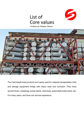
RCP INSTALLATIONINSTALLATION Safety Pipe Delivery/Handling Surveying Drainage Proper Eqpt./Material Leadership1.2.3.4.5.6.7.8.Locate UtilitiesPipe Installation ProceduresExcavate trench.Explore FoundationPlace structural bedding material to grade. Do not compact.Install pipe to grade.Compact structural bedding outside the middle third of the pipe.Place structural bedding in lifts.Complete structural backfill operation by working from side to side of the pipe,HcoverFinalBackfillDoIn-situ SoilMiddleThirdDiDo/3SpringlineBeddingFoundation12
Utilities Determine LocationLocate UtilitiesBegin excavationPhysically Locate UtilitiesExcavate trench with safety inmind– Sloped sides– Trench boxExcavate TrenchBest PracticesSafetyConsider Bedding ThicknessDon’t over/under excavateProper width of trenchExcavate TrenchBest PracticesSafetyConsider Bedding ThicknessDon’t over/under excavateProper width of Trench13
Proper Trench WidthCompaction EquipmentYesYesCompaction EquipmentNoNoTrench BoxPipe Foundation Explore Foundation to determine the type andcondition of the foundation Explore to a depth equal to ½” per foot of fill height or8” (whichever is greater) Entrance Pipes of 12” to 30” diameter under 15’ of fillor less – no exploration is needed Stable Foundation must be provided to ensureproper line and grade is maintained14
Pipe FoundationPipes and box culvertsFoundationCrusher run aggregate sizeNo. 25 or 26---------------------------------When standing water is in pipefoundation area, No. 57 stone can beused as a backfill in the subfoundation:No. 57 stone MUST be capped with aminimum of 4” crusher run prior toplacement of pipe or box culvertCompaction testing on No. 57 stoneis not required; seat stone in trenchBedding6” loosely placedShaped 10% of outside ØGraded to distribute loadCheck GradeStandard StandardInstallationInstallationBedding Standard Drawing D-8 Bedding:– Class C Bedding 6” Min. Loose Sand or Type C Borrow– Class A Bedding 6” minimum plus Imbed pipe in concrete 6” for pipessmaller than 24”; 10” for pipes 24” to 60”; and for pipeslarger than 60” see project details15
Bedding Ensure bedding follows gradelevel for bottom of pipe to ensurecontinuous support along barrel ofpipe Uneven bedding creates unevenpipe invert and induceslongitudinal stresses in pipe.Place Structural Bedding to GradeBest PracticesLoosely PlacedRocky Foundation Requires MoreTake Your Time - Importation StepPlace Structural Bedding to GradeBest PracticesLoosely PlacedRocky Foundation Requires MoreTake Your Time - Importation Step16
Install Pipe to GradeBest PracticesUse Proper EquipmentCheck Bedding Elevation/GradeDownstream to upstream (bell up)Install Pipe to GradeBest PracticesKeep Pipe off BeddingProtect Joint from DamageAvoid Pushing Down to get GradeLift Hole and Plug in Concrete Pipe17
Joints(Joining Pipe Sections)What Function Do Pipe Joints Perform?1.Provide flexibility and resiliency for movement.2.Provide for expansion and contraction.3.Guard against leakage.4.Connect like materials.5.Transition between unlike materials.6.Transmit or transfer load.7.Reduce stress on the material or structuralmember.8.Other?What Function Do Pipe Joints Perform?18
Joint Assembly Joining Pipe:Begin at the downstream end (Bell faces upstream)Ensure spigot and bell are clean and free of debris.Liberally Lubricate spigot and bell with pipe lubricant.Is Contractor aware of the maximum insertion angle?Fully insert pipe. (Make a Mark on Outside of Pipe)Moving pipe around after joining may cause pipe joint to work apart. Rigid pipe - properly fitted, sealed with rubber, preformed plastic, masticgaskets Flexible Pipe - properly aligned and joined with approved coupling bandsCMP Joint BandsDimpleGilesAnnularJoint Options for HDPE Gasketed Spigot & Bell Joint (STor WT) Split Band Coupler is used forplain end pipe or joining pipesthat have been field cut.Standard GasketedJointSplit Band CouplerPlain End Pipe19
Joint Sealing Options for RCPButyl Mastic & Profile Rubber GasketsRubber O-RingProfile RubberGasketsCompact Structural Bedding(Outside Middle 1/3 of Pipe)Best PracticesPrevent Pipe from ShiftingCompact in Lifts (6” to 4”)Use Proper Compaction EqptStandard Installation20
Backfill Material Pipe– Borrow Type C for pipe trenches below the roadway orshoulders, 95% or more of maximum density– Borrow Type C for pipe trenches other than belowroadway or shoulders, to a height 12” above top ofpipe and remainder to depth shall be backfilled withexisting material. 90% or more of the maximumdensity– Place an initial backfill lift that does not exceed 12” ofloose material or no higher than springline. Slicebackfill into the haunches. Place lifts no greater than8” loose material.Pipe & Box Culvert Backfill Excavation must be wide enough toaccommodate compactionequipment Simultaneously backfill on bothsides Static roll until fill is 4 feet above topof pipe or box Rocks 2” must be moved awayfrom structures a minimum of 12”Final Backfill12” Min CoverAbsolute min 12”(except entrances 9”)Standard Installation21
Complete Structural BackfillBest PracticesPrevent Pipe from ShiftingPlace in Lifts (8”)Use Proper Compaction EqptComplete Structural BackfillBest PracticesAlternate from One Side to NextTrench Width Allows CompactionProper Material for BackfillAdditional BackfillingConsiderations Allow 48” of cover whereheavy constructionequipment travels overpipe22
Connections to StructuresPipe openings in precast drainage units shall not exceedthe outside cross sectional dimensions of the pipes bymore than a total of 8 inches regardless of theplacement of the pipe, their angles of intersection, orshapes of the pipes.Pipe – Structure ConnectionsPipe ConnectionsRigid to RigidFlexible Connections w/Flexible Pipe8 inch (Maximum) GapGrouting/BootingPipe – Structure ConnectionsPipe ConnectionsRigid to RigidFlexible Connections w/Flexible Pipe8 inch (Maximum) GapGrouting/Booting23
Pipe – Structure ConnectionsProper Connection MaterialRigid to RigidFlexible to FlexibleDon’t Take Short-cutsPipe – Structure ConnectionsBest PracticesManhole Adapters:A-Lok, Z-Lok, Kor-N-SealPipe – Structure ConnectionsProper Connection MaterialRigid to RigidFlexible to FlexibleDon’t Take Short-cuts24
Post Installation InspectionPost Installation Inspection per DelDOT’s StormSewer CCTV Manual for Storm Sewer Assessmentand Acceptance and specificatoinsPost Installation Inspection1.Visual/ Video/Mandrel Inspection required on:– All Storm Sewer Pipes (100%)– Selected Number of Pipe Culverts ( 10%)2. Must be done with DelDOT Rep Present3. Conducted no sooner than 30 days after completion ofInstallation and placement of final cover (except pavement)Effects of Poor Installation All pipes– Open and offset joints Rigid pipes– Cracks– Lift holes not plugged Flexible pipes– Deflection– Cracks/Dents25
Effects of Poor Installation Poor Quality JointsMigration of finesSinkholesLoss of pipe foundationEventual pipe failureDefects Reinforced Concrete Pipe1.2.3.4.5.6.Illegal brandMisalignment (vertical and horizontal)SpallsSlabbingCracks greater than 0.1” in widthCracks greater than 0.01” in width and showingefflorescence or differential settlementDifferential joint movementImproper gasket placementJoint leakageSettlementJoint separations exceeding manufacturer’s 2.13.14.15.12‐36”42” and largerAll Elliptical0.75”1.25”1.5”Illegal brandUneven lapsDeflection greater than 7.5%Elliptical shaping (circular pipe only)Misalignment (vertical and horizontal)Ragged or diagonal sheared edgesLoose, unevenly lined or spaced rivetsImperfectly formed rivet headsUnfinished endsLack of rigidityBruised, scaled or broken protective coatingDents or bends in the metalImproperly seated bells/spigotsBulging or hanging gasketsJoint separations exceeding manufacturer’s recommendation or as follows:a.12-36”0.75”b.42” and larger1.25”c.All Elliptical1.5”Defects Metal Culverts26
Defects HDPE1.2.3.4.5.6.7.8.Illegal brandDeflection greater than 5.0%Misalignment (vertical and horizontal)Connections with a gap exceeding 3/16”Cracking or tearingCreasesUnpigmented or non-uniformly pigmented pipeJoint separations exceeding manufacturer’s recommendation Deflection Limits:a. 5% ‐ no remediation requiredb.5% to 7.4% ‐ shall be evaluated if pipe has additional defects along withdeflection in this range pipe shall beremediatedc. 7.4% ‐ Pipe shall be replaced Deflection Remediation Options:a. 5% ‐ 100% of Unit Bid Priceb.5% to 7.4% ‐ 75% of Unit Bid Pricec. 7.4% ‐ Pipe shall be Removed and Replaced Buckling, Bulging and Rackinga.Flat spots or dents at the crown, sides of flow linedue to racking shall be noted and evaluated Cracks and CoatingsCommon Types of Pavement Drains UD-1 (Standard Groundwater) UD-4 (Standard Pavement) (new construction) UD-7 (Standard Retrofit) (retrofitting existing)(found in Road and Bridge Standards)27
UD-4 Standard PavementUD-7 Standard RetrofitPavement DrainsComponentsTrench (.5 to 1% long slope)Non-woven geotextile drainage fabricPerforated long pipe (35 psi min.) collectorAggregate backfill (#8 or #57)Non-perforated smooth wall outlet pipe (35 psi)An end-wall for outlet pipe protectionPavement DrainsPavement Drains PerformanceInterceptCollectDischarge28
General Underdrain Installation avate trench making sure walls are stable.Remove any sloughed materials from trenchExcavated material picked up with conveyor and/or front end loader and removed fromsite.Minimum of 0.5 to 1.0% longitudinal slopeOpen on as much trench as can be safely managedLine trench with non-woven drainage fabricInstall long. perf. pipe at bottom of trench w/out beddingPlace 45 deg. elbow at end of run, connect longit. pipe to non-perforated outlet pipe todischarge water. Drainage sideConnect outlet pipe to back of end-wallBackfill trench with #8 or #57 aggregate asap nlt end of day.Backfill depth is at least equal to diameter of pipe.Backfill is usually placed loosely & heaped above finish levelUse vibratory place with welded foot to compact agg. BackfillFold drainage fabric to provide 100% overlap at top of trenchUD-4, Open Graded Drainage Layer placed on top of trenchUD-7, as asphalt cap is used to complete backfilling & provide the final surface is even withshoulder.Inspect once complete to ensure no areas are crushed, clogged or non-functioning.Inspect per VTM-108.Conclusion Storm Sewers and Culverts have a direct effect onRoads. The Inspectors level of commitment to requiring theContractor to follow DelDOT Standards will have adirect effect on long term DelDOT Maintenance Costsand the long term Quality of Delaware Roads. 1. Before starting to dig what should be located?Utilities2. True or False. When moving concrete pipe you should pick itup by one end.False3. What is maximum size rock to be placed no closer than 12inches from pipe .2”4. What is the maximum backfill lift thickness?8 inches loose (12” initial lift)5. What is the maximum backfill lift thickness?8 inches loose (12” initial lift)29
6. Pipe openings in precast drainage structures shall not exceedthe outside cross sectional dimensions of the pipe by more than 8 inches 7. The video inspection can be doneafter installation iscomplete. 30 days 8. The maximum allowed crack size of rigid pipe is. 0.1 inches. 9. The maximum deflection allowed for flexible pipe is. 5.0% for HDPE and 7.5% for CMP10. What end of the pipe system do you start installation?downstream (bell pointed upstream)11. What is the level of compaction required for pipe backfill?95% under roadways and shoulders12. What is the minimum amount of cover over pipe allowed fordesign loads? 12” minimum). 9” entrances (exception) 13. What is the minimum amount of cover over pipe to preventdamage from construction loads? 4 feet 30
Proper Pipe Installation Practices . Sewer CCTV Manual for Storm Sewer Assessment and Acceptance and specificatoins Post Installation Inspection 1. Visual/ Video/Mandrel Inspection required on: - All Storm Sewer Pipes (100%) - Selected Number of Pipe Culverts ( 10%) 2. Must be done with DelDOT Rep Present