Transcription
THIS STANDARD PRACTICE WAS DEVELOPED AS A GUIDE TO ASSIST THE ACPAINFRASTRUCTURE COMMITTEE’S MARKET TEAMS IN CREATING OR MODIFYINGSPECIFICATIONS IN THEIR MARKET AREAS. IT IS EXPECTED THAT CERTAIN PORTIONS OFTHIS STANDARD MAY NOT BE APPLICABLE TO ALL MARKETS. SOME OF THE CONTENTS INTHIS DOCUMENT COULD BE COPYRIGHTED. AS SUCH, THE USER SHOULD NOT “CUT ANDPASTE” LARGE SECTIONS OF THIS DOCUMENT AND PLACE INTO A NEW OR EXISTINGSPECIFICATION. THIS IS AN INTERNAL DOCUMENT INTENDED FOR THE USE OF ACPAMEMEBERS WORKING WITH AGENCIES TO IMPROVE THEIR SPECIFICATIONS, BUT IT SHOULDNOT BE DISTRIBUTED TO OUTSIDE AGENCIES.STANDARD PRACTICE FOR THE DESIGN AND CONSTRUCTION OF REINFORCEDCONCRETE STORM SEWER PIPE (RCP)PART 1: GENERAL1.01 SCOPE OF WORKFurnish all labor, materials, equipment and incidentals necessary to manufacture and testreinforced concrete gravity sewer pipe and fittings as shown on the drawings and specifiedherein.1.02 REFERENCE SPECIFICATIONSExcept as modified or supplemented herein, all precast reinforced concrete pipe shallconform to the applicable requirements of the following specifications, latest edition.A.AASHTO (American Association of State Highway and Transportation Officials)AASHTO LRFD Bridge Design SpecificationsM288 Standard Specification for Geosynthetic Specification for HighwayApplicationsPP63 Standard Practice for Pipe Joint Selection for Highway Culvert and StormDrainsR73 Standard Practice for Evaluation of Precast Concrete Drainage ProductsB.ASCE (American Society of Civil Engineers)ASCE 15 Standard Practice for Direct Design of Buried Precast Concrete PipeUsing Standard Installations (SIDD)C.ASTM (ASTM International)C76 Standard Specifications for Reinforced Concrete Culvert, Storm Drain andSewer PipeC443 Standard Specification for Joints for Concrete Pipe and Manholes, UsingRubber GasketsC506 Standard Specification for Reinforced Concrete Arch Culvert, Storm Drain,and Sewer PipeC507 Standard Specification for Reinforced Concrete Elliptical Culvert, StormDrain, and Sewer Pipe
C655 Reinforced Concrete D-Load Culvert, Storm Drain and Sewer PipeC822 Standard Terminology Relating to Concrete Pipe and Related ProductsC877 Standard Specification for External Sealing Bands for Concrete Pipe,Manholes, and Precast End SectionsC969 Standard Practice for Infiltration and Exfiltration Acceptance Testing ofInstalled Precast Concrete Pipe Sewer Lines.C990 Standard Specification for Joints for Concrete Pipe, Manholes, and PrecastBox Sections Using Preformed Flexible Joint SealantsC1417 Standard Specification for Manufacture of Reinforced Concrete Sewer,Storm Drain, and Culvert Pipe for Direct DesignC1479 Standard Specification for Installation of Precast Concrete Sewer, StormDrain, and Culvert Pipe Using Standard InstallationsC1840 Standard Practice for inspection and acceptance of installed reinforcedconcrete culvert, storm drain, and storm sewer pipe.D2487 Standard Practice for Classification of Soils for Engineering Purposes(Unified Soil Classification System)D2488 Standard Practice for Description and Identification of Soils (VisualManual Procedures)D.OSHA (Occupational Health and Safety Administration)29 CFR 1926 OSHA Construction Industry Regulations and StandardsPage 2 of 23
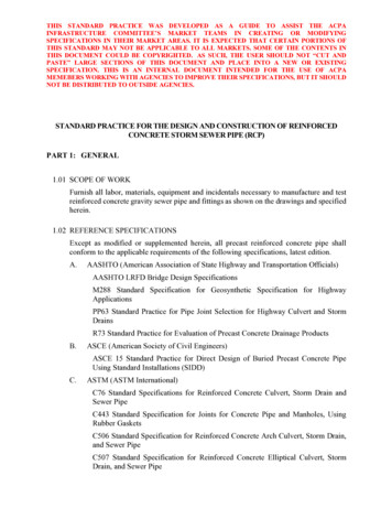
1.03 RESOURCESA.B.Design1.ACPA Design Data 92.AASHTO LRFD Bridge Design Specifications - Section 12 Buried Structuresand Tunnel Liners3.AASHTO LRFD Bridge Design Specifications - Section 34.National Cooperative Highway Research Program (NCHRP) – Synthesis 474Service Life of CulvertsFlotation1.ACPA Design Data 22 Buoyancy of Concrete Pipe2.ACPA Concrete Pipe Handbook Sec 5-25 through 5-33 Buoyancy of ConcretePipe3.ACPA ePipe #10 Flowable FillC.ADT Limits: Georgia Department of TransportationD.Post Installation Inspection1.Subcommittee on Construction Guide for Pipe Culvert Inspection for NewConstruction2.ASTM C1840 Standard Practice for Inspection and Acceptance of InstalledReinforced Concrete Culvert, Storm Drain, and Storm Sewer Pipe.3.ACPA Sample Specification for Evaluation of Newly Installed Culvert andStorm Drainage Pipe4.ACPA Post Installation Inspection Methods, Tools, and Reports5.ACPA Post Installation Evaluation and RepairE.Connections to Structures: Texas Department of Transportation Standard Inlet &Manhole ProgramF.Trench Box1.South Carolina Department of Transportation2.Washington Department of TransportationG.Submittal DataH.The contractor shall submit to the Engineer certifications verifying that all pipe andrelated products supplied meet the applicable specifications and requirements of thisstandard.I.If required by the engineer, pipe product details showing joint and pipe dimensionsshall be included in the submittal information.1.04 DEFINITIONSA.Figure 1 illustrates the definitions and limits of the terms; foundation, subgrade,bedding, haunch, lower side, initial backfill, pipe zone, embedment zone, backfill orPage 3 of 23
overfill, invert, crown, springline, top of pipe, and bottom of pipe as used in thisStandard.Figure 1 – Pipe TerminologyB.For definitions of terms related to concrete pipe, see ASTM C822.C.For terminology related to soil classifications, see ASTM D2487 and ASTM D2488.D.For terminology and definition of terms related to structural design, see AASHTOLRFD Bridge Design Specifications.E.For terminology and definition terms related to pipe joints, see AASHTO PP63.Page 4 of 23
PART 2: DESIGN2.01 GENERALA.Reinforced concrete pipe shall be manufactured in accordance with ASTM C76,ASTM C655, ASTM C506, and ASTM C507, and designed using the indirect methodshown in the American Concrete Pipe Association Design Data 9.B.As an alternate to the indirect design methods described in Design Data 9, reinforcedconcrete pipe is permitted to be manufactured in accordance with ASTM C1417, anddesigned using direct design procedures per ASCE 15-98 Standard Practice for DirectDesign of Buried Precast Concrete Pipe Using Standard Installations (SIDD).C.For pipe installed below the water table, an analysis checking for possible flotationshall be required.2.02 MATERIALS AND MANUFACTUREA.Except as otherwise specified herein, all pipe and appurtenances shall conform to theapplicable ASTM or ASCE Standard. Submittal data shall include all materialsassociated with the pipe product. The strength designation of the pipe shall be asspecified on the Drawings or as submitted by the manufacturer.B.Circular reinforced concrete culvert and storm sewer pipe shall be manufactured inaccordance with ASTM C76, C655, C1417 or special design. Gasketed joints shallsealed in accordance with ASTM C443. Tongue and groove joints shall be sealedwith mortar or preformed flexible sealant per ASTM C990, or other suitable sealant.Page 5 of 23
Pipe with elliptical reinforcing or quadrant mats shall be clearly marked to indicatethe top of the pipe or have a lift hole or lift anchors to ensure proper orientation.C.Arch Reinforced concrete culvert and storm sewer pipe shall be manufactured inaccordance with ASTM C506. Joints shall be tongue and groove sealed with mortaror preformed flexible sealant per ASTM C990, or other suitable sealant.D.Elliptical reinforced concrete elliptical culvert and storm sewer pipe shall be inaccordance with ASTM C507. Joints shall be tongue and groove sealed with mortaror preformed flexible sealant per ASTM C990, or other suitable sealant.2.03 HYDRAULICSA.When hydraulically sizing the precast reinforced concrete pipe, a Manning’s ‘n’ valueof 0.012 shall be used.B.Lab values shall not be used due to in-field condition of debris and build-up in thepipe.2.04 FLOTATIONA.Where water is present in the trench during installation, the contractor shall dewaterthe trench to maintain line, grade and proper compaction.B.When ground water is present after installation, designers shall calculate downwardforces acting on the pipe, such as soil, to ensure buoyancy of the pipe is less than thedownward forces.Note: Costal area with shallow installation and high water table is a commonscenario where flotation could be a concern for concrete pipe.C.Although flowable fills are not generally required for concrete pipe installations,backfill of RCP installations involving a flowable backfill or cement slurry beddingshall be placed with equal volumes of materials in alternating equal lifts to preventflotation or additional stress on the pipe. The potential for pipe flotation shall becalculated using the density of the flowable fill (approximately 130 lbs/ft3)2.05 PIPE JOINT SELECTIONA.The joint selection process to determine the appropriate joint type shall be done inaccordance with AASHTO PP63.B.The pipe joint shall consist of a bell (or groove) on one end of a unit of pipe and aspigot (or tongue) on the adjacent end of the joining pipe. Plain joints utilizingPage 6 of 23
mortar, mastic, external geotextile wraps, and rubber gaskets are all considered soiltight joints when assembled correctly in the field.C.D.E.F.Soil-tight Joint1.If water movement through the joint to or from the surrounding soil isacceptable or even desirable, and where the migration of backfill through thejoint is not likely, then a soil-tight joint should be selected.2.Soil-tight joints are specified as a function of opening size (maximumdimension normal to the direction that soil may infiltrate), channel length(length of the path along which the soil may infiltrate), and backfill particlesize. If the size of the opening exceeds 1/8 in., the length of the channel mustbe at least four times the size of the opening. No opening may exceed 1 in.Silt-tight Joint1.If infiltration of backfill material is a concern, then the designer should examinethe composition of the backfill material. If there is a high percentage (more than35%) of soil fines passing the No. 200 sieve, then a silt-tight joint should beselected for most applications.2.Silt-tight concrete pipe joints that utilize an external joint wrap as the solemethod of sealing may include either (a) external sealing bands per ASTMC877 or (b) 12-in. wide geotextile fabric per M288 with an Apparent OpeningSize (AOS) 70.3.Silt-tight concrete pipe joints that utilize a rubber gasket or mastic filler as thesole method of sealing shall be subjected to a plant proof-of-design hydrostatictest in accordance with ASTM C443, except the maximum hydrostatic testpressure shall not be greater than 2 psi for the straight and deflected position.Leak-resistant Joint1.If limited joint leakage is acceptable, a leak-resistant joint should be selected.A leak-resistant joint limits water leakage at a maximum rate of 200gallons/inch-diameter/mile/day for the project specified head or pressure.2.Leak-resistant concrete pipe joints that utilize an external joint wrap as the solemethod of sealing may include an external sealing band per ASTM C877 Type1 or Type 2.3.Leak-resistant concrete pipe joints that utilize a rubber gasket or mastic filler asthe sole method of sealing shall be subjected to a plant proof-of-designhydrostatic test in accordance with ASTM C443 with the maximum hydrostatictest pressures of 10.8 psi in the straight alignment and 10 psi for the deflectedalignment.Special Joints1.If limited joint leakage is not acceptable, a special design joint shall bespecified. Special design joints include joints requiring additional strength inbending or shear, pull-apart capabilities, or unusual features such as retrainedjoints in severe slopes, welded, flanged and bolted joints for high pressures,high heads, or velocities.Page 7 of 23
2.Watertight joints that provide zero leakage for a specified head or pressureapplication are included in this category.G.Pipe joints shall be inspected to ensure dimensions and tolerances are in accordancewith the design joint. Pipe, gaskets, wraps, and all other materials used to make andseal the joint shall be inspected for compliance to their respective specifications.H.The pipe manufacturer shall perform plant verification tests in accordance with thePlant Test Requirements in AASTHTO PP63, when specified.2.06 TRAFFIC LIMITATION SELECTION GUIDELINE FOR CULVERT, SLOPE ANDUNDERDRAIN PIPETable 1 - GA DOT ADT Selection Guideline for Culvert, Slope, and Underdrain Pipe2.07 DESIGN LIFEA.For most storm sewers/culvert conditions reinforced concrete pipe has a design lifeof 100 years. The US Army Corps of Engineers, Engineering Manual gives RCP a100-year service life. States such as Arizona, Georgia, Kentucky, Connecticut,Alabama give RCP a 100-year service life with pH, chlorides and velocityrestrictions. Kansas, Louisiana, Michigan, Minnesota, Missouri, North Dakota,Page 8 of 23
Oregon, South Dakota, Ontario Canada, define the design life of a concrete pipebetween 70-100 years.B.Elements that may affect RCP service life are: Acids Sulfates Chorides Freeze-thaw and weathering Velocity-abrasion1.The interior and exterior effects of acid on RCP may be considered as shown inTable 2.Table 2 - Evaluation ProceduresExterior ExposureInterior ExposureFor potential bio-chemicalAccurately determine problems in sanitary sewers,determine rate of acidpH and total aciditydevelopment, if anyEvaluate installationconditionfromstandpoint of thepotentialacidreplenishment2.For acid effluents, inuous or intermittentflow characteristicsSulfatesThe Bureau of Reclamation has developed general criteria for evaluating anddealing with the chemical reaction of the concrete with sulfates, shown in Table3.Table 3 - Attack on Concrete Soils and Waters Containing Various Sulfate ConcentrationsPercent Water-SolubleRelative Degree ofPPM Sulfate (as SO4) inSulfate (as SO4) in SoilSulfate AttackWater SamplesSamplesNegligible0.00 to 0.100 to 150Positive10.10 to 0.20150 to 1,500Severe20.20 to 2.001,500 to 10,000Very Severe32.00 to more10,000 or more1Use Type II cement2Use Type V cement, or approved Portland-pozzolan cement providingcomparable sulfate resistance when in concretePage 9 of 23
3Use Type V cement plus approved pozzolan which has been determined bytests to improve sulfate resistance when used in concrete with Type V cementPage 10 of 23
3.Chloridesa.The most significant aggressive action of chlorides is corrosion of steel inreinforced concrete. Portland cement protects embedded steel againstcorrosion under conditions that would be highly corrosive to bare steel.This protection is an electro-chemical phenomenon in which the highalkalinity of concrete, normally a pH of 12, passivates the steel. Thispassivating influence will normally remain effective provided the pHremains above 10. The chloride ion can disrupt the protective mechanism.The greater the chloride ion concentration beyond the critical level,assuming oxygen availability, the more rapid the corrosion will progress.b.For instances where chlorides and sufficient oxygen are both present theseverity of chloride attack may be reduced by increasing the concretecover, using higher concrete quality with low permeability or using abarrier type protective coating.4.Freeze-thaw and Weathering: This has not been shown to be a concern forconcrete pipe.5.Velocity-abrasiona.At velocities around 40 feet per second, or greater, cavitation effects canbe serious unless the surface is smooth and internal offsets at joints areclosely controlled. Within the range of velocities up to 40 feet per second,the severity of the abrasion depends on the bead load, which is thequantity of the solids being moved through the pipe by flow velocity.b.Increasing the compressive strength of the concrete along with an increasein the specific hardness of the aggregates used, increases the abrasionresistance.2.08 COLORADO DEPARTMENT OF TRANSPORTATION’S CORROSION ANDABRASION MATRIXA.B.Determine Abrasion Level1.Abrasion Level 1: This level applies where the conditions are nonabrasive.Nonabrasive conditions exist in areas of no bed load and very low velocities.This is the level assumed for the soil side of drainage pipes. This is also thelevel assumed for the inverts of cross drains and side drains installed in typicallydry drainages.2.Abrasion Level 2: This level applies where low abrasive conditions exist. Lowabrasive conditions exist in areas of minor bed loads of sand and velocities of5 fps or less.3.Abrasion Level 3: This level applies where moderately abrasive conditionsexist. Moderately abrasive conditions exist in areas of moderate bed loads ofsand and gravel and velocities between 5 fps and 15 fps.4.Abrasion Level 4: This level applies where severely abrasive conditions exist.Severely abrasive conditions exist in areas of heavy bed loads of sand, gravel,and rock and velocities exceeding 15 fps.Determine Corrosion LevelPage 11 of 23
C.Select Class of Pipe Required on the ProjectTable 4 – Guidelines for Selection of Corrosion Resistance LevelsPage 12 of 23
Note: The class of pipe listed is the result of the Abrasion and Corrosion Level. Forexample, if you have a Level 3 Abrasion, and Corrosion Level 1, the class of piperequired is Class 7. Proceed to Section 3.7.4 in this Standard.Figure 2 – CDOT Pipe Material Selection GuideD.Select Pipe Allowed on a Project Based on Corrosion and AbrasionTable 5 - Materials Allowed for Class of PipeClass of Pipe*Page 13 of 23
MaterialAllowed**01234564789104CSPYNNNNNNNNNNBit. Co. CSP YY1NNNNNNNNNA.F.CSPYYYYYYYNNNNYY2Y2Y2Y2YNNNNNPCSP - )3,5YYYYYNNYYYNRCP(SP3)3,5YYYYYYYYYYYBo.CAP*As determined by the Department in accordance with the CDOT Pipe Selection Guide. Determinationis based on abrasion and corrosion resistance.** Y Yes; N No.12345Coated Steel Structural Plate Pipe of equal or greater diameter, conforming to Section 510, may besubstituted for Bit. Co. CSP at no additional cost to the project.Aluminum Alloy Structural Plate Pipe of equal or greater diameter, conforming to Section 510, maybe substituted for CAP at no additional cost to the project.SP Class of Sulfate Protection required in accordance with subsection 601.04 as revised for thisproject. RCP shall be manufactured using the cementitious material required to meet the SP classspecified.For pipe classes 6 and 10, the RCP shall be coated in accordance with subsection 706.07 when the pHof either the soil or water is less than 5. The Contract will specify when RCP is to be coated.Concrete shall have a compressive strength of 4500 psi or greater.2.09 STRUCTURAL DESIGNA.This standard practice provides a guidance for both the indirect and direct designmethods and it is designed to be used by engineers who are familiar with the conceptof soil-pipe interaction and of principals used to perform design of concrete members.Both methods are explained in Section 12.10 (12.10.4.2 for direct design method and12.10.4.3 for indirect design method) of the AASHTO LRFD Bridge DesignSpecifications. The indirect method is also explained in the Concrete Pipe DesignPage 14 of 23
Manual, while the direct design is explained in the Concrete Pipe TechnologyHandbook and ASCE Standard Practice 15.B.While the indirect and direct design methods are markedly different they areessentially geared towards reaching the same overall objective, the selection of anappropriate balance of pipe structure and soil supporting structure for a given designcondition. Regardless of the design method used, the required steps to be followedare:1.Define design criteria: Inside diameter of the pipe. Location of the pipe with respect to the ground surface elevation. Type of installation. Calculate the applied loads which are generated by the earth cover,surcharge, live load, self-weight, and load applied from the fluidtransferred by the conduit.2.Structural Analysis of the Pipe (Indirect Design)a.Bedding factors are used to account for the ratio of the load capacity ofthe pipe under the installed condition and that of the pipe in the three-edgebearing (TEB) test at the plant. The bedding factors account for the effectof the soil-structure interaction, since they are defined based on the ratioof the strength of the pipe under the installed condition of loading andbedding to the strength of the pipe in plant test. The bedding factors canbe selected from Section 12.10 of the AASHTO LRFD Bridge DesignSpecifications or Chapter 4 of the Concrete Pipe Design Manual.b.The strength of the pipe is determined by defining an equivalent threeedge bearing (TEB) load that produces certain performance limits in thepipe. The pipe class strength is specified in terms of an appropriate TEBstrength to be supplied in conjunction with a specified installation type.The performance criteria for the TEB strength require pipe to reach teststrengths relative to two design limits: service load condition and ultimatestrength.Note: ASTM C76 defines the limits of the TEB based on the class of thepipe. Design requirements for different pipe classes are offered in C76 forcircular culvert, storm drain, and sewer. ASTM C506 and ASTM C507offer design requirements for arch and elliptical culvert, storm drain, andsewer, respectively.Page 15 of 23
3.Structural Analysis of the Pipe (Direct Design): For special designs that do notfall within the parameters of an ASTM C76 Class Pipe, the direct design methodmay be used. The steps for this are as follows:a.The pipe thickness, concrete strength, steel type and strength, concretecover, reinforcement arrangement need to be pre-selected.b.Select the load and resistance factors to define moment, thrust, and shear.The load and resistance factors are defined based on Sections 3.4 and 12.5of AASHTO LRFD Bridge Design Specifications, respectively.c.Determine the amount of reinforcement required based on the tensile yieldstrength limit state.d.Check if the provided reinforcement at the inside face of the pipe, causesradial tension stresses that are higher than the maximum radial tensionstrength limit. The reinforcement area based on the tensile yield strengthmust not exceed the area that produces the limiting radial tension strength.e.Check if the produced compressive strains exceeds the limits. Thereinforcement area, based on the tensile yield strength, must not exceedthe area that produces limiting compressive strain.f.For pipe with standard diameters and typical wall thicknesses, check if thecritical shear force at the wall sections where Mnu/Vud 3.0 exceeds theshear (diagonal tension) strength limit.g.Check if the service load moments at the crown, invert, or springline,combined with the associated thrusts, cause reinforcement stresses thatexceed the service load limit for crack width control.Page 16 of 23
PART 3: PART III: CONSTRUCTION3.01 ACCEPTANCE UPON DELIVERYA.Except as modified or supplemented herein, all precast reinforced concrete pipe shallconform to the applicable requirements of AASHTO R73.B.Any defective precast concrete pipe may be repaired per AASHTO R73, Section 5"Repairable Defects In Precast Concrete Products".C.All products should be accompanied by material certification by manufacturer whichshall include a written statement certifying that the steel used in the production of allPage 17 of 23
product delivered to the job site complies with all provisions of the "Buy AmericaAct".D.Pipe shall be subject to rejection in accordance with AASHTO R73, Section 6,“Rejectable Defects in Precast Concrete Products”.3.02 INSPECTION BEFORE INSTALLATIONA.All products are subject to final visual inspection for shipping and handling damage,fit and other visual defects and disposition to the project site in accordance withAASHTO R73.B.Verify concrete pipe acceptance report is current and covers manufacturing plant,pipe diameter, class of pipe, ASTM Standard the pipe was manufactured to, date thepipe was manufactured.3.03 QUALITY ASSURANCEA.Post-Installation Performance Requirements for Joints1.The standard procedures for verifying performance of the pipe joint in the fieldshall be done in accordance with the Field Test Requirements in AASTHTOPP63, when specified.2.Soil-tight Joint: Installed pipe joints shall have a visual or video inspection inthe field to ensure compliance to the project specifications. Open joints or jointsthat are flowing particles larger than those retained on a No. 200 sieve shall berepaired or replaced as necessary.3.Silt-tight Joint: Installed pipe joints shall have a visual or video inspection inthe field to ensure compliance to the project specifications. Open joints or jointsshowing sediment as a result of flowing infiltration or exfiltration of particlessmaller than those passing the No. 200 sieve shall be repaired or replaced asnecessary.4.Leak-resistant Joint: Installed pipe joints shall have a visual or video inspectionin the field to ensure compliance to the project specifications. Open joints orjoints showing sediment as a result of measurable infiltration or exfiltrationshall be repaired or replaced as necessary. Leak-resistant concrete pipe jointsshall be tested to the performance requirements in accordance with ASTMC969.a.b.Infiltration Testing1)The allowable leakage limit is 200 gallons/in.-diameter/mile/daywhen the average head on the test section is 6 ft or less.2)When the average head on the test section is greater than 6 ft, theallowable leakage shall be increased in proportion to the ratio of thesquare root of the average groundwater head to the square root ofthe base head of 6 ft.Exfiltration Testing1)The allowable leakage limit is 200 gallons/in.-diameter/mile/daywhen the average head on the test section is 3 ft or less.Page 18 of 23
2)c.When the average head on the test section is greater than 3 ft, theallowable leakage shall be multiplied by the ratio of the square rootof the average test head and the square root of the base head of 3 ft.For either infiltration or exfiltration testing, manholes shall be testedseparately and independently or with the pipeline with the allowance of0.1 gal/ft of MH diameter/ft of head/hour. If building or house leads areconnected to the main line being tested, allowance shall be made forpermissible leakage in such leads.3.04 PIPE LAYINGA.Care shall be taken in loading, transporting, and unloading to prevent damage to thepipe.B.Preparation of bedding and backfill shall be as specified on the Drawings and per therequirements of the American Concrete Pipe Association’s Design Data 9 or ASTMC1479. Pipe shall be laid with uniform bearing under the barrel of the pipe. Forprojecting bell pipe, bell holes shall be provided.C.Pipe shall not be laterally displaced by pipe embedment material installed as providedin the Drawings. No pipe shall be laid in unsuitable bedding conditions such as, butnot limited to, water in the trench or hard rock. Pipe shall be laid with bell endsfacing the direction of laying except when making closures.D.When the design requires special bedding conditions for culverts or storm drains, anexcavation diagram will be shown on the plans. Do not exceed these limits ofexcavation. The length of trench excavation in advance of pipe laying shall be keptto a minimum.E.All material excavated from trenches and piled adjacent to the trench shall bemaintained so that the toe of the slope is at least 2 feet from the edge of the trench. Itshall be piled to cause a minimum of inconvenience to public travel, and provisionshall be made for merging traffic where necessary. Free access shall be provided toall fire hydrants, water valves, and meters; and clearance shall be left to enable freeflow of storm water in gutters, conduits, or natural watercourses.F.Rubber gaskets shall be installed in strict conformance with the pipe manufacturer’srecommendations.G.Pipe shall be laid to line and grade as shown on the plans. Adjustments in grade byexerting force on the barrel of the pipe with excavating equipment or by lifting anddropping the pipe shall be prohibited. If the installed pipe section is not on grade, thepipe section shall be completely un-joined, the grade corrected, and the pipe thenPage 19 of 23
rejoined. Curves may be formed using fittings, specials, beveled end pipe orunsymmetrical joint closure of straight pipe.3.05 SOIL COVERA.Construction Soil Cover1.If the passage of construction equipment over an installed culvert is necessaryduring project construction, compacted overfill in the form of a ramp shall beconstructed to a minimum elevation of 3.0 ft over the top of the culvert or to aheight such that the equipment loads on the culvert do not exceed the culvertdesign strength.2.In an embankment installation, the overfill shall extend a minimum of oneculvert diameter width or 3.0 ft whichever is greater, beyond each side of theculvert to prevent possible lateral displacement of the culvert.3.If a large volume of construction traffic must cross an installed culvert, the pointof crossing shall be changed occasionally to minimize the possibility of lateraldisplacement.B.Minimum Soil Cover: The minimum soil cover for final backfill of an installedculvert shall not be less than 1.0 ft over the top of the culvert regardless of pavementtype, unless a special design is performed.C.Maximum Soil Cover1.The maximum soil cover for final backfill of an installed culvert shall not begreater than 40.0 ft over the top of the culvert for standard culverts andinstallations depending on diameter of the culvert and installation type. Whengreater soil cover is expected, a special design is required and should bedesigned and installed per the manufacturer’s recommendations.2.For soil cover specifics based on diameter of the culvert, see the latest versionof the LRFD Fill Height Tables provided by the American Concrete PipeAssociation, which is based on the latest version of the AASHTO LRFD BridgeDesign Specifications.3.06 TRENCH BOXESA.If trench boxes are required for trenches less than 20 feet deep, follow OSHA 29 CFR1926.652, trench box manufacturer, and industry standards.
Storm Drain, and Culvert Pipe for Direct Design C1479 Standard Specification for Installation of Precast Concrete Sewer, Storm Drain, and Culvert Pipe Using Standard Installations C1840 Standard Practice for inspection and acceptance of installed reinforced concrete culvert, storm drain, and storm sewer pipe.


