Transcription
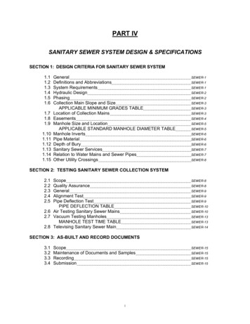
PART IVSANITARY SEWER SYSTEM DESIGN & SPECIFICATIONSSECTION 1: DESIGN CRITERIA FOR SANITARY SEWER .141.15GeneralDefinitions and AbbreviationsSystem RequirementsHydraulic DesignPhasingCollection Main Slope and SizeAPPLICABLE MINIMUM GRADES TABLELocation of Collection MainsEasementsManhole Size and LocationAPPLICABLE STANDARD MANHOLE DIAMETER TABLEManhole InvertsPipe MaterialDepth of BurySanitary Sewer ServicesRelation to Water Mains and Sewer PipesOther Utility SEWER-6SEWER-7SEWER-7SEWER-8SECTION 2: TESTING SANITARY SEWER COLLECTION SYSTEM2.12.22.32.42.5ScopeQuality AssuranceGeneralAlignment TestPipe Deflection TestPIPE DEFLECTION TABLE2.6 Air Testing Sanitary Sewer Mains2.7 Vacuum Testing ManholesMANHOLE TEST TIME TABLE2.8 Televising Sanitary Sewer ER-10SEWER-13SEWER-13SEWER-14SECTION 3: AS-BUILT AND RECORD DOCUMENTS3.13.23.33.4ScopeMaintenance of Documents and 5SEWER-15
SECTION 4: 3ScopeQuality AssuranceProduct Delivery, Storage and HandlingPrecast Concrete ManholesCast-In-Place ManholesMortarGroutRing and CoverStepsPreformed Plastic GasketsInspectionPreparationManhole SEWER-19SEWER-19SECTION 5: GRAVITY SANITARY SEWER COLLECTION copeQuality AssuranceJob ConditionsManholesPipeSanitary Sewer Service LinesInspectionPreparationConnections to Existing SystemPipe InstallationManhole InstallationSanitary Sewer Service ConnectionsField Quality -26SEWER-26SECTION 6: SANITARY SEWER SERVICE LINES6.16.26.36.46.56.66.76.86.9ScopeQuality AssuranceJob ConditionsPipeFlexible CouplingsGeneralTrenching, Backfilling and CompactionTapsService LinesSECTION 7: SANITARY SEWER SYSTEM DETAILSSTANDARD MANHOLE DETAILSHALLOW MANHOLE DETAILINSIDE/DROP MANHOLESEWER SERVICE ALTERNATIVE CONNECTIONUNDERDRAIN/MANHOLE CONNECTION WER-27SEWER-27SEWER-27SEWER-28
PART IVSANITARY SEWER SYSTEM DESIGN & SPECIFICATIONSSECTION 1. DESIGN CRITERIA FOR SANITARY SEWER SYSTEM1.1 GeneralThe purpose of this section is to provide information for the design and layout of a sanitary sewercollection system acceptable to the Johnstown Waste Water Department (JWWD). All sanitarysewer system design shall be in accordance with the requirements of this section and the Town ofJohnstown Standard Construction Specifications for Sanitary Sewer Construction.1.2 Definitions and AbbreviationsA.Collection Mains1.B.Interceptor Sewer1.C.An interceptor, or main, sanitary sewer carries flows from the collections sewers to apoint of treatment or disposal of the wastewater.Sanitary Sewer Services1.D.A sanitary sewer collection main is defined as a system that gathers flows directlyfrom individual building services and transports the material to an interceptor ormain sewer.All pipe and fittings used to convey sanitary sewage from the plumbing system in abuilding to a collection main.Abbreviations1.2.3.4.cfsfpsgpcdgpdcubic feet per secondfeet per secondgallons per capita per daygallons per day1.3 System RequirementsA.Design Flow1.The sanitary sewer collection system design shall include consideration for providingservice for the entire area tributary to the outfall point. Sanitary sewer flowinformation for the existing collection system may only be obtained from the Town.Estimates for sanitary sewer flows shall use the following guidelines:a.Residential sewage contribution shall be based on 100-gpcd average flows.SEWER-1
b.c.d.Minimum residential population density shall be figured on a basis of 2.5persons per house, six (6) houses per acre and, 70% of total land areadeveloped as residential, unless detailed analysis of the proposed servicearea indicates differently.Estimates shall include allowances for a maximum infiltration of 100 gallonsper day per inch diameter per mile of pipe.Commercial and industrial sewage contribution estimates shall be submittedto the Sewer Department for review prior to design acceptance1.4 Hydraulic DesignA.Sanitary sewer grades shall be designed to produce flow characteristics as close tooptimum as is physically and economically feasible.1.The size of pipe required shall be computed by Manning’s Equation.Q 1.486AR2/3 SnWhere:2.Q Flown Manning’s Coefficient of Coefficient, 0.013A Area of Flow (ft2)R Hydraulic Radius (A/P)Where P Wetted PerimeterS Slope of pipe (ft/ft)All sanitary sewer collection pipes shall be designed to flow maximum half full(d/D 0.5) at design flows.Where:d Depth of FlowD Diameter of PipeThe design depth of flow should be greater than two-inches (2”) where practical.3.Optimum velocities are four (4) to five (5) feet per second (fps) at design flow. Theminimum and maximum velocity at the design flow rate shall be two (2) fps andfifteen (15) fps respectively unless prior written acceptance is to received from theWater and Sewer District.1.5 PhasingA.Sanitary sewer phasing, if proposed, must meet the following conditions for acceptance:1.Shown on the master utility plan.2.Terminal manhole shall be located at either the phase line or subsequent nextmanhole in the adjoining phase.A stub out for future phasing may be made by providing a block out in the terminalmanhole for future lines. The inverts in the terminal manhole shall be called out forall pipes entering and exiting the manhole.3.SEWER-2
1.6 Collection Main Slope and SizeA.In addition to the criteria stated in Section 1.4, Hydraulic Design, the following shall apply tosanitary sewers:1.2.Sanitary Sewer mains shall be eight-inch (8”) diameter or larger. Serviceconnections are four-inch (4”) diameter or larger.Table 1.6-1 displays the applicable minimum grades per pipe diameter. Theseminimum grades may be used provided Section 1.4 criteria are met.TABLE 1.6-1APPLICABLE MINIMUM GRADESSewer Diameter4 inch6 inch8 inch10 inch12 inch15 inch18 inch21-inchMinimum Grade ect to Section 1.4, Hydraulic Design3.4.The maximum grade for any sanitary sewer line shall be 5.00% unless prioracceptance is obtained from the JWWD.If the JWWD requires the Developer to install a collection main larger than neededto adequately serve the development, the Town may reimburse the Developer forthe extra materials cost and depth of excavation above what is required for thedevelopment. Extra material costs shall include on the difference between the sizeof pipe and manholes. Extra depth costs shall include only the extra depth ofexcavation required to install the pipe in excess of what would have been requiredfor the development. Material prices must be verified from supplier’s invoices andthe extra depth costs must be shown on the Contractor’s bid sheet. All prices mustbe accepted by the Town prior to start of construction.1.7 Location of Collection MainsA.Sanitary sewer mains shall be extended to the greater distance of either the far or upstreamedge of the end service lot or property, regardless of where the tap is made, or to the edgeof the platted subdivision. The Town may grant exception to this requirement ifdevelopment of adjacent property is infeasible and/or unforeseeable.B.The centerline of sanitary sewer mains shall not be placed closer than eight feet (8’) to theface of an existing or future curb, gutter, or walk without written acceptance by the Town.SEWER-3
C.All sewer mains shall terminate at a manhole.D.A stub out of future extensions shall consist of a block out for future pipes in the terminalmanhole. The stub out shall consist of a block out for future pipes in the terminal manhole.The invert elevations shall be shown for pipes entering and exiting the manhole.E.Sewer lines shall be straight – not curved – between manholes, both in line and grade.F.Clean outs on sewer main lines shall be prohibited.1.8 EasementsA.When the Sewer Department determines it is not feasible for an installation in a dedicatedstreet right-of-way, the installation shall be made in an easement. The conditions forallowance of such an exception shall be determined for each individual case. The minimumeasement width acceptable by the Sewer Department is as follows:1.2.3.4.For a dedicated sanitary sewer easement, the width shall be twenty feet (20’) ortwice the depth to the invert of the water pipe, whichever is greater, and shall be forthe exclusive use of Town of Johnstown water mains. These easements shall belabeled on the construction and plat documents as “EXCLUSIVE SEWER LINEEASEMENT.”For a combined sanitary sewer and water easement, the total width shall be twicethe maximum depth to the invert of the sanitary sewer line plus twice the maximumdepth to the invert to the water pipe or thirty feet (30’), whichever is greater.The easement width will be required to be wider than the minimum widths previouslystated if the line depth would require additional width to be able to safely excavatearound the pipe without the use of a trench box.The sanitary sewer line shall be located a minimum ten feet (10’) from the edge ofthe easement, or equal to the depth to the pipe invert, which ever is greater.B.The Sewer Department shall have the exclusive utility use of the exclusive sanitary sewerand sanitary sewer easements except for angled utility crossings. The Sewer Departmentshall review for acceptance all utility crossing methods prior to construction.C.All easement documents shall be recorded prior to construction drawing acceptance.D.The easement shall be COMPLETELY CLEAR OF landscaping greater than three feet (3’)tall (mature growth), permanent structures, and storm water detention ponds.SEWER-4
1.9 Manhole Size and LocationA.Table 1.9-1 displays the applicable diameter of standard manholes per pipe diameter.TABLE 1.9-1APPLICABLE STANDARD MANHOLE DIAMETERSewer Pipe Diameter8 inch to 15 inch15 inch to 36 inch48 inch and largerManhole Diameter48 inch60 inchSewer Dept AcceptanceB.Manholes shall be provided at every change in direction, grade, or connection with othersewer mains.C.Maximum manhole spacing shall be 450 feet (450’) for lines ten-inches (10”) or smaller, or550 feet (550’) for lines twelve-inches (12”) or larger.D.The center of any manhole shall not be placed closer than eight feet (8’) to the face of anexisting or future curb, gutter, or sidewalk.E.A minimum ten feet (10’) horizontal separation shall be maintained from the center of thesanitary sewer manhole and any other utility.F.Manholes outside of road right-of-ways should be located in areas that are not subject toflooding from surface runoff. No manholes shall be located in areas where ponding orstorm detention basins are to be used.1.2.If the possibility of surface runoff cannot be avoided a solid manhole cover, with anintegral O-ring type gasket that can be bolted closed must be used.All manholes that are to be designed and constructed with a watertight, bolted typecover, the manhole ring shall be bolted to the manhole cone, and all manhole jointsand grade rings shall be sealed from the outside with an approved seal wrap.G.There shall be no more than three (3) lines designed to discharge into any one manhole.This includes service lines.H.Rim and invert elevations of all lines (including services) entering and exiting a manholeshall be shown on the project plans in the profile view.I.Manholes shall be located in areas that allow direct access by Town maintenance vehicles(up to 35 tons) via all weather roads. An all-weather road design shall be submitted by aqualified Geotechnical Engineer to the Town for acceptance prior to construction drawingapproval.J.The Design Engineer shall determine if conditions require a protective coating to protect themanhole from corrosion.SEWER-5
1.10 Manhole InvertsA.Inverts of a straight channel sanitary sewer manhole, without laterals, may be set by usingthe same grade as the main provided that the upstream and downstream grades are thesame and the manhole is constructed by laying pipe through the manhole and removing theupper half of the pipe. Refer to Standard Details for this type of manhole construction.B.If the conditions in 1.10.A cannot be maintained, the minimum elevation drop across astraight channel manhole shall be one-tenth-of-a-foot (0.1’).C.Where a sanitary sewer of the same size changes direction by 30 or more, the inlet andoutlet flowline elevations shall have at least two tenths-of-a-foot (0.2’) difference across themanhole.D.When a tree invert is constructed with the inlet(s) and outlet being the same size, the invertscoming into the manhole must be at least two tenths-of-a-foot (0.2’) higher than the outletinvert.E.Where a smaller sewer joins a larger on a straight channel, the smaller sewer crownelevation shall match the crown elevation of the larger line. This includes service lines.F.Where a sanitary sewer lateral main connects to a sanitary trunk sewer with a diameter often inches (10”) or more, the crown elevation of the lateral main shall match the crownelevation of the trunk sanitary sewer line.G.Inside drop manholes shall be provided for a sewer entering a manhole with an elevationtwenty four-inches (24”) or more above the manhole invert.1.H.Drop inlet pipes equal to or greater than 10 inches shall require a 60-inch diametermanhole.Where the invert elevation difference is less than two feet (2’) but greater than six-inches(6”), the invert shall be filleted, as shown on Standard Details, to prevent solids deposition.1.11 Pipe MaterialA.Standard residential development shall use polyvinyl chloride (PVC) SDR 35 pipe suitablefor sanitary sewer flows. The Design Engineer shall specify acceptable pipe material forcommercial or industrial applications for corrosive or solvent-entrained wastewater and anyother conditions that require a non-SDR35 PVC pipe. The Town shall approve use andlength of the specified pipe.1.12 Depth of BuryA.Sewer mains shall have a minimum cover of four feet (4’) to the finished ground surface.B.Where minimum cover provides less than nine feet (9’) of elevation difference between thefinished lot grade at building line and the top of the sewer main, the plans and the plat shallindicate that the lot is served by a “shallow sewer” and appropriate elevation informationshall be given.SEWER-6
1.13 Sanitary Sewer ServicesA.Each structure and each subdivided lot shall be served by separate service lines. Nocompound services are allowed.B.All lots shall have separate sewer services without crossing any adjacent properties.C.Service lines shall be designed with a minimum fall as shown in Table 1.6-1.D.Service lines shall have a maximum velocity of ten feet per second (10 fps).E.The service line shall flow maximum half full at peak design flow.F.The minimum allowable service line size is four-inches (4”).G.Sanitary sewer services shall be located ten feet (10’) down grade, or down stream, of thewater service wherever feasible. Certain cul-de-sacs may have the sewer service linelocated further than ten feet (10’) off the water service t allow the sewer service not to belocated under a driveway.H.Service lines may not be installed in trenches with other conduits. A service line shall beseparated from other conduits a minimum of ten feet (10’) horizontally.I.Clean-outs shall be located at all points of deflection (i.e. bends) and every 100 feet (100’) ina service line with the following exception:1.J.No clean out shall be located within a public right-of-way.Each lot or separate building site shall have tees or tapping saddles for service connections.1.Service tees or tapping saddles on the main shall have a minimum five feet (5’)separation.K.Riser connections shall be prohibited.L.All service lines greater than six-inch (6”) diameter shall be connected at a manhole. Thisservice connection shall channel the flow through the manhole bench to the invert unlessthe difference in invert elevations is greater than twenty-four inches (24”). See Section4.10.07.1.14 Relation to Water Mains and Sewer PipesA.Sanitary sewer services and collection mains shall be located horizontally a minimum of tenfeet (10’) centerline to centerline of existing or proposed water or storm lines.SEWER-7
B.Where sanitary sewer lines cross water mains, the sanitary sewer pipe shall have aminimum eighteen-inches (18”) clear distance vertically below the water main. If this cleardistance is not feasible or the sanitary sewer line is above the water line, the crossing mustbe designed and constructed, using pipe encasement on the sanitary sewer main, to protectthe water main. Refer to Standard Details for construction.C.Storm sewers shall have the same restrictions as water mains.1.15 Other Utility CrossingsA.The minimum horizontal separation shall be ten feet (10’) when parallel in the public right-ofway. The same restrictions as sanitary sewer shall apply.B.Right angle crossings are permitted under the sanitary sewer pipe with a two-foot (2’)vertical clearance.1.Tunneling or boring is preferable but if open cut is the only solution, the trench shallbe as narrow as possible and backfill shall be flowfill from the top of the lower pipeup to the spring line of the sanitary sewer pipe.C.For crossings above the sanitary sewer pipe, the utility crossing shall have a minimumeighteen-inches of vertical clearance and be installed in High Density Polyethylene pipe(HDPE), Standard Dimension Ratio (SDR) 11 from edge to edge of the easement or right-ofway or ten feet (10’) either side of the sanitary sewer line, which ever is greater.D.Sanitary sewer crossings of open irrigation ditches shall be detailed, have four feet (5’)minimum cover, and be approved by the ditch company. See Standard Details for typicalpipe crossing requirements.SECTION 2: TESTING SANITARY SEWER COLLECTION SYSTEM2.1 ScopeA.This section addresses the testing of sanitary sewer collection mains, manholes, andappurtenances.1.2.3.All sanitary sewer pipelines shall be air tested per these specifications.All sanitary sewer manholes shall be vacuum tested per these specifications.All sanitary sewer collection systems shall be video inspected per thesespecifications.2.2 Quality AssuranceA.Standards (as applicable).1.2.ASTM C1244, Standard Test Method for Concrete Sewer Manholes by theNegative Air Pressure (Vacuum), latest revision.ASTM F1417, Standard Test Method for Installation Acceptance of PlasticGravity Sewer Lines Using Low-Pressure Air, latest revision.SEWER-8
2.3 GeneralA.Testing shall be conducted when:1.2.B.The Contractor shall furnish all equipment, labor, and incidentals necessary to performtests.1.C.The maximum allowable pressure gauge shall be 0.1 psi.The Town shall witness tests and record times, leakage readings, and pressure over thetest period.1.D.Backfill and compaction has been completed but before street improvements areinstalled.Main and manholes have been thoroughly cleaned of all foreign material.Contractor shall provide the Town a minimum 48 hours advance notice of anytests.All tests shall occur after completion of backfilling and compaction but prior to pavingunless otherwise stated in these specifications.2.4 Alignment TestA.Video each section of sanitary sewer between manholes to determine whether anydisplacement of pipe has occurred.1.2.3.4.Videoing shall be done after pipe trench is compacted and brought to grade orpavement subgrade and submitted to the Town.“Full moon” shall be visible for grand alignment.No less than “half moon” shall be visible for horizontal alignment.Repair poor alignment, displaced pipe, or other defects discovered.2.5 Pipe Deflection TestA.Each section of sanitary sewer shall be tested for deflection by an independent testingfirm as hired by the Contractor prior to Town acceptance and as deemed necessarywithin the warranty/construction period by the Town.1.2.The maximum allowable deflection for Town acceptance is 5% of the baseinternal diameter.The maximum allowable deflection at the end of the warranty period shall be7.5% of the base internal diameter.SEWER-9
3.Mandrel outside diameters in inches is as follows:Pipe SizeBase I.D.5% 719.00421.35624.06168101215182124274.7.5% 18.50420.79423.427Sections of the pipe that fail the deflection test shall have the defects repaired andthe test repeated.2.6 Air Testing Sanitary Sewer MainsA.Conduct tests in conformance with ASTMF1417, Time Pressure Drop Method, and thesespecifications.B.Preparation for tests:1.2.3.C.Flush and clean the sewer line prior to testing in order to wet the pipe surfacesand produce more consistent results.Provide a relief valve on the pressuring equipment to avoid over-pressurizing anddamaging an otherwise acceptable line.a.Set relief valve at 5 psi.Plug and brace all openings in the main sanitary sewer line and the upperconnections.a.Check all pipe plugs with a soap solution to detect any air leakage.b.If leaks are found, release the air pressure, eliminate the leaks and startthe test procedures over again.Test Procedure1.2.Add air until the internal pressure of the sewer line is raised to approximately 40psi gage.a.Maintain the air pressure between 3.5 psig and 4.5 psig until the airtemperature in the pipe is stabilized with the pipe/ground temperature.Disconnect the air supply and reduce the air pressure to 3.5 psig before startingthe test.a.If the groundwater is higher than the top of the pipe, the test pressureshall be adjusted to account for the high groundwater. The test pressureshall be increased by 0.43 psi per foot of ground water up to five feet (5’)of ground water. For ground water over five feet (5’) in depth, aninfiltration test shall be conducted in place of the air test. Contact theJWWD for infiltration testing procedure and criteria.SEWER-10
3.Determine the time required for the air pressure to drop from 3.5 psig to 2.5 psig.a.The time elapsed shall not be less than:T 0.085(DK)(Q)Where:T Shortest time (s) allowed for the air pressure to drop 1.0pisgK 0.000419 DL but not less than 1.0Q leak rate in cubic feet/minute/square feet of internalsurface 0.0015 CFM/SFD measured average inside diameter of pipe (in)L length of test section (ft)b.Example calculation for an 8-inch diameter sanitary sewer pipe with a testsection 400 feet long:[T 0.085 8in(0.00419)(8in)(400ft)0.0015CFM/SF]T 608 seconds or 10 minutes 08 seconds (10:08)c.The following table contains the test durations for pipe diameters betweenfour (4”) and fifteen (15”) inches, for pipe lengths up to 500 feet. The testdurations for pipe larger than fifteen-inches (15”) shall be calculated usingthe formula given above.SEWER-11
4.If lateral or service lines are included in the test, their length may be ignored forcomputing required test time if the test time requirements are met. If the testsection fails, time shall be recomputed to include all the lateral lengths using thefollowing formula:a.5.If the recomputed test time is short enough to allow the section tested topass, then the test section meets the requirements of this specification.Sections of the pipe that fail the air test shall have the defects repaired and thetest repeated.SEWER-12
2.7 Vacuum Testing ManholesA.Manholes shall be tested before the ring and cover and grade adjustment rings areinstalled, and after backfill and compaction is complete.B.Conduct tests in conformance with ASTM C1244 and these specifications.C.Preparation for tests:1.2.D.All lift holes, joints, and other imperfections shall be filled with an approved nonshrink grout, to provide a smooth finish appearance.All pipes entering the manhole shall be temporarily plugged, taking care tosecurely brace the pipes and plugs to prevent them from being drawn into themanholes.Test Procedure:1.2.3.The test shall be placed at the top of the manhole in accordance with themanufacturer’s recommendation.A vacuum of 10-inches mercury shall be drawn in the manhole, the valve on thevacuum line of the test head closed, and the vacuum pump shut off.a.The time shall be measured for the vacuum to drop to 9-inches mercury.The manhole shall pass if the time for the vacuum reading to drop from 10-inchesmercury to 9-inches mercury meets or exceeds the values indicated in thefollowing table.Minimum Test Times for Various Manhole DiametersDiameter (in)6072Time 11Round actual depth of manhole to next depth up (ex. 11 foot deepmanhole, use depth of 10 feet).Depth1 (ft)4.48If the manhole fails any test, necessary repairs shall be made by an approvedmethod and the manhole shall be retested until a satisfactory test is obtained.SEWER-13
2.8 Televising Sanitary Sewer MainA.All sanitary sewer lines shall be televised three (3) months prior to the end of thewarranty period or as deemed necessary within the warranty/construction period by theTown. The televising shall be made by the Contractor or a Sub-consultant to thecontractor and the recording shall be submitted to the Town for acceptance.1.2.3.4.5.B.The recording shall be made using a color camera, self-propelled or other havingsufficient light to show detail of problem areas and joints.Camera shall have a swivel head capable of looking up each service connection.Camera speed shall not exceed three feet (3’) per second.If problem areas or concerns are seen by operator, then the camera shall bebacked up and an extended look at the area will be recorded.All recordings will have location (i.e. manhole # to manhole #), time, date, andfootage displayed.The warranty period for the sanitary sewer collection system WILL continue to be ineffect for the time specified in Town of Johnstown Water and Sewer ConstructionSpecifications, latest edition, or until the JWWD has received and approved the videorecordings, which ever is longer.END OF SECTIONSEWER-14
SECTION 3: AS-BUILT AND RECORD DOCUMENTS3.1 ScopeA.This section addresses the As-Built Drawings and Record Documents for theconstruction of sanitary sewer collection mains, sanitary sewer facilities, andmiscellaneous appurtenances.3.2 Maintenance of Documents and SamplesA.Store documents in Contractor’s field office apart from documents used for construction.1. Provide files and racks for storage of documents.2. Provide storage space for samples.B.File documents and samples in accordance with the specification’s section numbers.C.Maintain documents and samples in a clean, dry legible condition and in good order. Donot use as-built and record documents for construction purposes.D.Documents shall be made available for inspection by the Town upon request.3.3 RecordingA.Label each drawing “AS-BUILT RECORD DRAWING” in neat large printed letters.B.Record information concurrently with construction progress.1.C.Marking of Project Records.1.2.D.Do not backfill Work until required information is recorded.Legible and with a dark pen or pencil.Ink shall not be water based or subject to easy smearing.Mark Drawings to record actual construction.1.2.3.4.5.Field dimensions, elevations, and details.Changes made by a Town approved modification.Details not on original Drawings.Horizontal and vertical locations of underground utilities and appurtenances,referenced to a minimum of two permanent surface improvements.Depths of various elements in relation to project datum.3.4 SubmissionA.Submit as-built information to the Project Engineer to review and prepare final As-BuiltRecord Drawings.SEWER-15
B.Accompany the submittal to Project Engineer with a transmittal letter in duplicatecontaining:1.2.3.4.5.DateProject title and numberContractor’s name, address, and telephone numberIndex containing title and number of each Record DocumentSignature of Contractor or his authorized representativeC.All As-Built Record Drawings submitted to the Town for approval shall be on 24” x 36”blueline or blackline form.D.Final acceptance of the utility lines will not be given until the As-Built Record Drawingshave been submitted to and accepted by the Town.1.2.3.Warranty period will not begin until the Town gives initial acceptance.No certificate of occupancy will be issued for structures connecting to water andsanitary sewer until the Town gives final acceptance of the As-Built RecordDrawings.The site Developer will be responsible for utility locate until the Town gives finalacceptance of As-Built Record Drawings.SECTION 4: MANHOLES4.1 ScopeA.This section addresses sanitary sewer manholes, and includes the acceptable products,materials, and construction practices which may be used in the construction andinstallation of manholes.B.Manholes shall be furnished with all accessories, including steps, base, cone section,and ring and cover.C.Manholes shall be installed wherever there is a change in size, direction, slope, atjunctions, and intervals of not more than four hundred feet (400’) for 10-inch and smallerdiameter pipe and five hundred feet (500’) for pipe diameters greater than 10-inches.4.2 Quality AssuranceA.Standards (as applicable)1.2.3.ASTM A185, Standard Specification for Steel Welded Wire Fabric, Plain, forConcrete Reinforcement, latest revision.ASTM A615, Standard Specification for Deformed and Plain Billet-Steel Bars forConcrete Reinforcement, latest revision.ASTM A996, Standard Specification for Rail-Steel and Axel-Steel Deformed Barsfor Concrete Reinforcement, latest revision.SEWER-16
4.5.6.7.8.9.10ASTM B108, Standard specification for Aluminum-Alloy Perman
4. The sanitary sewer line shall be located a minimum ten feet (10') from the edge of the easement, or equal to the depth to the pipe invert, which ever is greater. B. The Sewer Department shall have the exclusive utility use of the exclusive sanitary sewer and sanitary sewer easements except for angled utility crossings. The Sewer Department
