Transcription
H. S. Saleh, et al., Int. J. Comp. Meth. and Exp. Meas., Vol. 6, No. 3 (2018) 605–613ULTIMATE CAPACITY OF PAD EYES USED FOR LIFTINGOPERATIONS: EXPERIMENTAL AND NUMERICALSIMULATIONSHIKMAT SAAID SALEH, SAMDAR KAKAY & SUDATH C. SIRIWARDANEDepartment of Structural and Mechanical Engineering and Materials Science, Faculty of Science and Technology,University of Stavanger, Norway.ABSTRACTLoad capacities of pad eyes used in offshore lifting operations are generally determined based onthe guidelines given in lifting standards. In 2012, NORSOK issued a new standard, R-002 ‘Liftingequipment’, to ensure that adequate safety requirements are complied with in connection with lifting operations on the Norwegian continental shelf. To ensure the accuracy of the followed designprocedure, this paper presents a comparison of theoretical load capacities of 3.25-ton pad eyes withexperimentally and numerically predicted load capacities. Several laboratory tests have been performedto conduct experimental analyses of the load capacities of pad eyes. These tests have included differentpinhole sizes in the pad eyes, different strain directions of pad eye pinholes and different loads to whichthe pad eyes were subjected. Finite element (FE) simulation was performed for two different cases:with base plate and without base plates. The obtained numerical results show that the addition of theplate to the pad eyes increased the capacity of the pad eyes. It also shows that load capacity of the padeyes gradually decreased with the increase in pinhole size. This shows the importance of following thestandard’s requirements. The comparison of results shows that some of the load capacities providedby the FE analysis closer to the experimental and the theoretical results, while a few others were quitefar from them. These differences have been comprehensively discussed in the latter part of the paper.Keywords: FE analysis, load testing, offshore lifting, pad eyes1 INTRODUCTIONOffshore activities on the Norwegian continental shelf include the lifting from sea to platform, using a platform crane, of smaller modification structures. Objects vary in shape, sizeand weight, many weighing below 50 tons, and it would be of great advantage if calculationsregarding such lifting operations could be standardized.In 2012, NORSOK issued a new standard, R-002 ‘Lifting equipment’ [1], to ensure thatadequate safety requirements are complied with in connection with lifting operations on theNorwegian continental shelf. Among the lifting equipment, pad eyes and shackles play amajor role in ensuring the safety of lifting operations [1–4].The most commonly used theoretical approaches for estimating the load capacity of padeyes are mainly based on stress limit states. This practice does not capture the local deformation-induced buckling or twisting and large-plastic deformation at the interface of the pad eyeand shackle. The finite element (FE) method employed numerical tools, which may help tosolve this problem to some extent, but the lack of precious ductile failure criteria, which areemployed in current commercial software [5, 6], may hinder in better prediction to loadcapacity and deformed behavior by numerical approach. To overcome these problems tosome extent, tests are conducted to evaluate experimental load capacities for pad eyes and tostudy their behavior in plastic state of stress. However, the problem with experimentalapproaches is that they can be exhausting, time-consuming and somewhat expensive. Therefore, it is necessary to make available a simpler, equally precise, less time-consuming andmore cost-effective approach for estimating load capacities of pad eyes. 2018 WIT Press, www.witpress.comISSN: 2046-0546 (paper format), ISSN: 2046-0554 (online), http://www.witpress.com/journalsDOI: 10.2495/CMEM-V6-N3-605-613
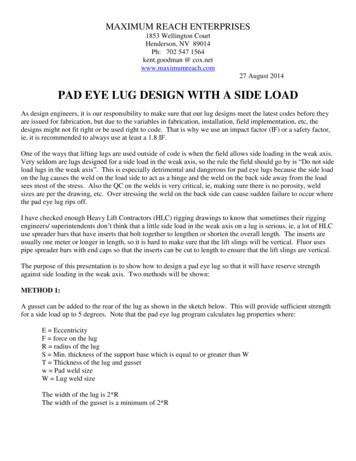
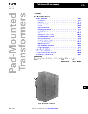
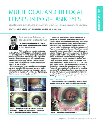
606H. S. Saleh, et al., Int. J. Comp. Meth. and Exp. Meas., Vol. 6, No. 3 (2018)To ensure the accuracy of the followed design procedure, this paper presents a comparisonof the theoretical load capacities of 3.25-ton pad eyes with experimental and numericalresults. To conduct the experimental analyses of the design load capacity of pad eyes, severaltests must be conducted, and a part of the results has been presented previously [7]. Thesetests include different pinhole sizes in the pad eyes, different strain directions of pad eyepinholes, and different loads to which the pad eyes were subjected. FE simulation was performed for two different cases: with base plate and without base plates. Initially, the paperreviews various factors that it is important to consider in a lifting operation and provides animportant theoretical basis. Then, details related to the execution, analysis and results of theexperimental testing are discussed briefly, while citing the authors’ previous paper. Thenumerical approach associated with load capacity determination is comprehensively discussed in this paper. Finally, the load capacities obtained by the above three approaches arecompared and their differences are discussed in the final part of the paper.2 PAD EYES AND SHACKLESThis section describes the types of pad eyes (also called lugs) and the technical requirementsfor lifting operations. A demonstration of the lifting terminology is shown in Fig. 1. Threemain types of design geometries for pad eyes are described in NORSOK R-002 lifting standard [1]. Type 1 is made of plate, with a uniform thickness, as shown in Fig, 2. Type 2 is madeof cheek plates attached to the main plate by a fillet weld, as shown in Fig. 2, while type 3consists of partly connected boss by full penetration welds as shown in Fig. 2.Shackles are made up of a U-shaped body and a pin, often secured with a bolt. They areused together with different lifting devices, and the size of the shackle is relative to the holediameter of the pad eye, as shown in Fig. 3. Pad eyes should also be designed to match thestandard shackle dimension so that the shackle can house both the pad eye and the preferredsling or hook.Figure 1: A demonstration of the lifting set terminology [7].
H. S. Saleh, et al., Int. J. Comp. Meth. and Exp. Meas., Vol. 6, No. 3 (2018) 607Figure 2: Different types of pad eyes.Figure 3: Pad eye and shackle interface.3 DESIGN LOAD CAPACITY: THEORETICAL APPROACHThis section describes the design criteria that are used to predict the load capacities of padeyes and shackles. This criteria-based approach is recognized as the most common and theone which is generally used for pad eyes and shackles.The design tearing off load of pad eyes can be derived as,Pt 2 τ Rd Ash(1)where τ Rd f y / γ m,1 3 is the design shear strength, and Ash ( R dh / 2 ) t p is the tearing outarea. f y is the tensile yield strength of the plate material, and γ m,1 is the partial safety factorfor the material specified by N-004 [8]. R represents the outer radius, while dh is the holediameter of the pad eye plate and t p is the thickness of the plate.The design bearing load of the pad eyes can be obtained as,Pb fb, Rd teff d(2)where fb, Rd 1.5 f y / γ m,1 is the design shear strength and teff t p is the effective thickness ofthe plate. f y is the tensile yield strength of the plate material and t p represents the thicknessof the plate. γ m,1 is the partial safety factor for the material specified by N-004 [8], while d isthe diameter of the shackle bolt, as shown in Fig. 3.
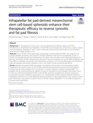
608H. S. Saleh, et al., Int. J. Comp. Meth. and Exp. Meas., Vol. 6, No. 3 (2018)4 LOAD CAPACITY: EXPERIMENTAL APPROACHThis section describes the details of the specimens and the experimental test setup. The padeyes, which have a safe working load (SWL) of 3.25 tons, are only tested in this study. The10 different pad eyes were produced by changing the hole diameter. The geometrical detailsand more detailed information of the test program have been clearly stated in the publisheddissertation [7].The pad eyes were welded to the plates using full penetration welds and 8-mm joints. Thewelds were then tested using magnetic particle inspection and ultrasound, the most commonly used NDT methods, to verify that the test specimens were fabricated with the desiredfixity without significant defects. In addition to the pad eye test specimens, shackles withcorresponding dimensions were also an important part of the tests. The shackles were used asconnection points between the tension cylinder, the dynamometer and the pad eye specimens.Quasi-static load test were conducted by changing different directions, as shown in Table 1.The fracture loads and displacement at failure are recorded in Table 1. The deformed or fractured pad eye specimens are shown in Fig. 4, while the deformed shapes of some of theshackle components are as displayed in Fig. 5.5 LOAD CAPACITY: NUMERICAL APPROACHThis section describes the details of the FE simulation and the load capacity estimation ofsame pad eyes, which have a SWL of 3.25 tons. The analysis was performed for two differentcases: with base plate and without base plates. The general-purpose FE package, Abaqus/CAE, is used for this analysis. S355 steel has been used for both pad eyes and base plates.The three FE models of case 1 (i.e. pad eye without base plate) are shown in Fig. 6. The otherthree FE models of case 2 (i.e. with pad eye with base plate) are shown in Fig. 7.The elastic-plastic analysis of the pad eye using Abaqus/Explicit was then performed forall the test scenarios previously mentioned in Section 4. The nonlinear mix/combined hardening behavior of S355 steel was considered for elastic-plastic analysis. The obtainedstress contours of the FE models are closely observed to recognize the critical zones andthen for further mesh refinements. A mesh convergence test was also performed. The bottom surface of the FE models of case 1 was fixed. The fixed boundary was used at theTable 1: Comparison of the load capacities of pad eyes.TheoreticalExperimentalFEM simulationPad eye withoutplatePad eye withplateTestLoad capacity(Tons)Load capacity is(mm)13456726.220.715.326.220.715.3 21 2114.5 14 15 0.53.5large dislarge dislarge dislarge dis
H. S. Saleh, et al., Int. J. Comp. Meth. and Exp. Meas., Vol. 6, No. 3 (2018) 609Figure 4: Fractured or/and deformed test specimen of pad eyes [7].Figure 5: Permanent deformation of shackle components after the test [7].circumference of the boltholes of the base plate. Both geometrical and material nonlinearity were considered in the incremental analysis. The FE simulation results, includinglocations vulnerable to ductile fracture, are shown in Figs 8 and 9 for cases 1 and 2, respectively. The load capacities were determined by considering the ductile fracture. The ductile
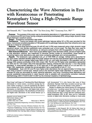
610H. S. Saleh, et al., Int. J. Comp. Meth. and Exp. Meas., Vol. 6, No. 3 (2018)Figure 6: FE mesh of case 1 (i.e. pad eyes without base plate): (a) pinhole diameter 22 mm,(b) pinhole diameter 32 mm, (c) pinhole diameter 42 mm.Figure 7: FE mesh of case 2 (i.e. pad eyes with base plate): (a) pinhole diameter 22 mm, (b)pinhole diameter 32 mm, (c) pinhole diameter 42 mm.fracture was determined when von Mises effective stress or strain exceeds material ultimate strength or strain, respectively. The obtained load capacities are shown in Table 1.6 COMPARISON AND DISCUSSIONIn this section, comparisons are made for all three different types of approaches for designingthe load capacity of pad eyes. The experimental, theoretical and, finally, FE-simulation-basedload capacities for the load capacity of 3.25-ton pad eyes are shown in Table 1. Each of thesix tests in the table below are now discussed individually.Test 1: In the case where the pad eye is without a plate, the load capacities given by FEanalysis are larger than both the theoretical and the experimental load capacities, while thedisplacements are much smaller than the experimental deformation. In the case of the pad eyewith the addition of the plate, the test specimens can carry the same amount of load as the
H. S. Saleh, et al., Int. J. Comp. Meth. and Exp. Meas., Vol. 6, No. 3 (2018) 611Figure 8: Stress distribution and fracture locations for case 1 (i.e. pad eyes with out baseplate): (a) Test 1, (b) Test 3, (c) Test 4, (d) Test 5, (e) Test 6, (f) Test 7.theoretical design load, without going to failure, and can withstand larger loads than theirexperimental counterparts. This shows that, when following the standards (as the pad eyegeometries, on which test 1 is based, are in accordance with NORSOK R-002 [1], while teststwo and three are not totally based on NORSOK R-002), very reliable and precise simulationresults can be obtained. Moreover, it can be seen from the table that the amount of displacement for the pad eye with the plate is much greater and closer to the experimental results thanfor the pad eye without the plate; this is due to the fact that this deformation of the plate isnow also a part of the global deformation of the pad eye. From Table 1, it can be seen that theexperimental load capacity has no particular value, as it is 21 tons, which means that it cancarry more than 21 tons without being subjected to failure.
612H. S. Saleh, et al., Int. J. Comp. Meth. and Exp. Meas., Vol. 6, No. 3 (2018)Figure 9: Stress distribution and fracture locations for case 1 (i.e. pad eyes with base plate):(a) Test 1, (b) Test 3, (c) Test 4.Test 3: In the case where the pad eye is without the plate, the load capacity given by FEanalysis is larger than both the theoretical and the experimental load capacities, while thedisplacements are again far from the experimental results. In the case of the pad eye with theplate, the simulation load capacity is even larger. Regarding the displacements, it is againobserved that the displacement for the pad eye with the plate is much greater than that for thepad eye without the plate,
This section describes the design criteria that are used to predict the load capacities of pad eyes and shackles. This criteria-based approach is recognized as the most common and the one which is generally used for pad eyes and shackles. The design tearing off load of pad eyes can be derived as, PA tR 2 τ ds h (1) where τγ Rd f ym