Transcription
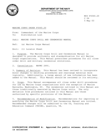
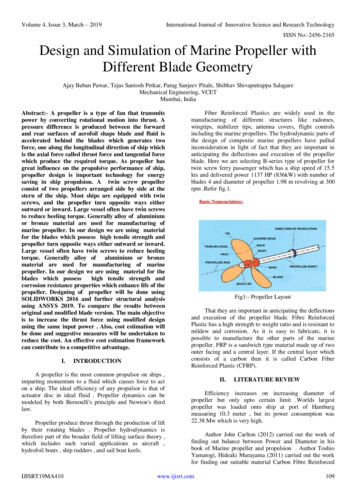
Volume 4, Issue 3, March – 2019International Journal of Innovative Science and Research TechnologyISSN No:-2456-2165Design and Simulation of Marine Propeller withDifferent Blade GeometryAjay Baban Pawar, Tejas Santosh Petkar, Parag Sanjeev Pitale, Shibhav Shivaputrappa SalagareMechanical Engineering, VCETMumbai, IndiaAbstract:- A propeller is a type of fan that transmitspower by converting rotational motion into thrust. Apressure difference is produced between the forwardand rear surfaces of aerofoil shape blade and fluid isaccelerated behind the blades which generates twoforce, one along the longitudinal direction of ship whichis the axial force called thrust force and tangential forcewhich produce the required torque. As propeller hasgreat influence on the propulsive performance of ship,propeller design is important technology for energysaving in ship propulsion. A twin screw propellerconsist of two propellers arranged side by side at thestern of the ship. Most ships are equipped with twinscrews, and the propeller turn opposite ways eitheroutward or inward. Large vessel often have twin screwsto reduce heeling torque. Generally alloy of aluminiumor bronze material are used for manufacturing ofmarine propeller. In our design we are using materialfor the blades which possess high tensile strength andpropeller turn opposite ways either outward or inward.Large vessel often have twin screws to reduce heelingtorque. Generally alloy of aluminium or bronzematerial are used for manufacturing of marinepropeller. In our design we are using material for theblades which possesshigh tensile strength andcorrosion resistance properties which enhance life of thepropeller. Designing of propeller will be done usingSOLIDWORKS 2016 and further structural analysisusing ANSYS 2019. To compare the results betweenoriginal and modified blade version. The main objectiveis to increase the thrust force using modified designusing the same input power . Also, cost estimation willbe done and suggestive measures will be undertaken toreduce the cost. An effective cost estimation frameworkcan contribute to a competitive advantage.I.INTRODUCTIONA propeller is the most common propulsor on ships ,imparting momentum to a fluid which causes force to acton a ship. The ideal efficiency of any propulsor is that ofactuator disc in ideal fluid . Propeller dynamics can bemodeled by both Bernoulli's principle and Newton's thirdlaw.Propeller produce thrust through the production of liftby their rotating blades . Propeller hydrodynamics istherefore part of the broader field of lifting surface theory ,which includes such varied applications as aircraft ,hydrofoil boats , ship rudders , and sail boat keels.IJISRT19MA410Fiber Reinforced Plastics are widely used in themanufacturing of different structures like radomes,wingtips, stabilizer tips, antenna covers, flight controlsincluding the marine propellers. The hydrodynamic parts ofthe design of composite marine propellers have pulledinconsideration in light of fact that they are important inanticipating the deflections and execution of the propellerblade. Here we are selecting B-series type of propeller fortwin screw ferry passenger which has a ship speed of 15.5kts and delivered power 1137 HP (836kW) with number ofblades 4 and diameter of propeller 1.98 m revolving at 300rpm .Refer fig.1.Fig1:- Propeller LayoutThat they are important in anticipating the deflectionsand execution of the propeller blade. Fibre ReinforcedPlastic has a high strength to weight ratio and is resistant tomildew and corrosion. As it is easy to fabricate, it ispossible to manufacture the other parts of the marinepropeller. FRP is a sandwich type material made up of twoouter facing and a central layer. If the central layer whichconsists of a carbon then it is called Carbon FiberReinforced Plastic (CFRP).II.LITERATURE REVIEWEfficiency increases on increasing diameter ofpropeller but only upto certain limit .Worlds largestpropeller was loaded onto ship at port of Hamburgmeasuring 10.3 meter , but its power consumption was22.38 Mw which is very high.Author John Carlton (2012) carried out the work offinding out balance between Power and Diameter in hisbook of Marine propeller and propulsion . Author ToshioYamatogi, Hideaki Murayama (2011) carried out the workfor finding out suitable material Carbon Fibre Reinforcedwww.ijisrt.com109
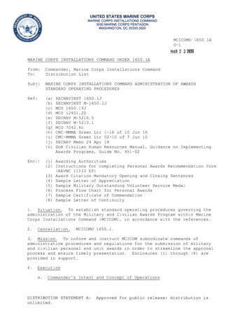
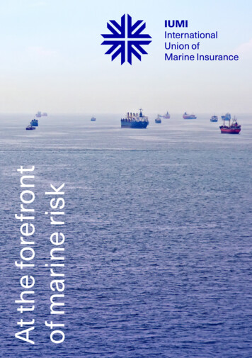
Volume 4, Issue 3, March – 2019International Journal of Innovative Science and Research TechnologyISSN No:-2456-2165Plastic (CFRP) by comparing the strength, degree ofvibration, cavitation between commonly used material(Aluminium alloy) and CFRP in his journal paper ofcomposite material marine propeller . H.N.Das, S.Kapuria(2013) carried out the experimental analysis to check theperformance of marine propeller. In journal paper of smartcomposite propeller for marine applications .John Carlton (2007) carried out detailed study ofblade geometry in his book of marine propeller andpropulsion . Author Frederikshavn (2015) carried outpropulsion calculation and performance of ship parametersand concluded rules for increasing propeller diameter andnumber of blades in his journal paper of basic principle ofship propulsion . Also, found out analysis of high efficientfixed pitch propeller in 2012 in book of MAN Alpha.M.M.Bernitsas ,D.Ray (1982) carried out propeller model ,test in open water in Netherlands and expressed optimalthrust , its coefficient and efficiency in terms of number ofblades in paper optimal revolution B-series propellers . Properties of CFRP:High flexibilityHigh tensile strengthLow weightHigh resistanceLow thermal expansionHigh strength-to-weight ratio Characteristics of CFRP:Specific gravityTensile strength and modulusCompressive strength and modulusDampingElectrical and thermal conductivitiesHigh costIII.Fig 2Fig 3:- Blade GeometryPROBLEM DEFINITIONThe main difficulty in most optimization problemsdoes not lie in the mathematics or methods involved , it liesin formulating the objectives of all the constraints . Thewrong type of propeller solution can have very negativeimpact on both the vessel and leads to low efficiency , highfuel consumption , low thrust force and low speed . Steps :- Modelling of marine propeller Step 1 :- Propeller Geometry :- ( Refer Fig.3 ) Pitch : - Theoretical distance a propeller would move inone revolution . Leading edge :- forward edge of blade , first toencounter the water stream . Trailing edge :- last part of the blade to encounter thewater stream . Skew angle :- It measures the degree of the generatorline relative to the shaft of the blade section. Rake angle :- Rake is the amount of degrees thepropeller blade angle perpendicular to the propeller hub. EAR(Expanded Area Ratio) :- Ratio of total blade areadivided by the propeller disc area. Refer fig.2.IJISRT19MA410Advantages of flow simulation :Low costTake less timeComplete informationAbility to stimulate realistic conditionsAbility to stimulate ideal conditionsReduction of failure risks.www.ijisrt.comFig 4:- Design of hub110
Volume 4, Issue 3, March – 2019International Journal of Innovative Science and Research TechnologyISSN No:-2456-2165 Step 2 :- Step 5 :-Fig 8:- Result of revolve cut Step 6 :Fig 5:- Blade design Step 3 :-Fig 9:- Circular pattern of blade Step 7 :Fig 6:- Swept blade geometry Step 4 :-Fig 10:- Boss tip designThe thrust force of a marine propeller when workingsufficiently far away from free surface may be expected todepend upon following parameters :Diameter(D) , Speed of advance(Vs) , rotation speed(n) ,density of fluid(ρ) , pitch(P) , Advance coefficient (J) ,wake fraction (w)Fig 7:- Revolve cutIJISRT19MA410 www.ijisrt.comFormula :A π(R)²P tan(α)* 2π* Rm A * Vs111
Volume 4, Issue 3, March – 2019International Journal of Innovative Science and Research TechnologyISSN No:-2456-2165 T ρ* m * (Vs – Vs*(1-w))J Vs (n * D )Kt T / (ρ * n² *D 4)Kq Q/ (ρ * n² *D 5)η (J * Kt )/ (2 π * Kq)IV.MATERIAL STUDYFiber Reinforced Plastics are widely used in themanufacturing of different structures like radomes ,wingtips , antenna covers , marine propellers , etc. FiberReinforced Plastic has high strength to weight ratio and isresistant to corrosion. Refer Table.1 & Table.2Young’s Modulus115 GPaPoisson Ratio0.328Density2700 gm/ccTable 1:- Nickel Aluminium Bronze mechanical propertiesYoung’s Modulus180 GPaPoisson Ratio0.28Density16 gm/ccTable 2:- Mechanical Properties of CFRPV.DETAILS OF ORIGINAL MODELParameterValuesTwist angle of blade30 Number of blades4Bending angle10 Diameter of propeller1980 mmDiameter of hub330 mmArea of blade2.504 m²Fig 12:- side viewThe next part is solidworks flow simulation 2016 oforiginal model with this initial conditions : Analysis type as external and exclude cavities withoutflow conditions, internal space. Select rotation and reference axis as rotating axis ( i.e Zaxis) Select fluid as water and flow type as laminar andturbulent. Take wall thermal conditions as adiabatic wall androughness as 0 micrometer (consider smooth surface ofpropeller ) Let the pressure be 101.325 kPa and temperature as293.2 K Enter velocity of flow at inlet as 7.08m/s in direction ofrotating axis.Now find the value of outlet axial velocity and thrustforce developed (i.e Force (Z) ) for various rotating speedin rad/s . Refer fig.13Table 3:- Considered DataFig 13:- Flow trajectories of original modelFig 11:- original designIJISRT19MA410The thrust force obtained for 300rpm rotation ofpropeller is 52.028 kN with outlet axial velocity of 18.312m/s. The mass of this propeller is 103.986 kg and totalwww.ijisrt.com112
Volume 4, Issue 3, March – 2019International Journal of Innovative Science and Research TechnologyISSN No:-2456-2165blade area of 2.504 m 2. The ansys structural analysis doneconcluded,Deformation (mm)Von-mises Equivalent Stess(MPa)CFRPNABCFRP7.6865.72267.739Table 4:- Material PropertiesNAB11.56VI.VII.RESULTSAnsys structural analysis is performed using ANSYSWORKBENCH 2016.Deformation and Von-Misses Stress of original modelwith its forces acting in all directions (i.e. Fx 1.8579 N ,Fy 59.036 N , Fz -52028 N ). Refer Table.9ModelDETAILS OF MODIFIED TRIALS TRIAL 1 :Here the thickness of blade is increased by 30%.Deformation( mm )NABCFRP11.567.68Von-misses Stress( MPa)NABCFRP65.72267.739OriginalmodelTable 9:- Deformation and Stress analysis TRIAL 2 :Here the blade width is decreased by 30%. TRIAL 3 :Here the number of blades is decreased by 1 (i.e. totalnumber of blades is 3 ) and blade width is increased by50%. TRIAL 4 :Here the a new blade design is done based onrequirements of results.ModelMass ( kg )% masscomparision125.61420.7 TRIAL 193.7369.8 TRIAL 2105.3271.3 TRIAL 3120.14215.5 TRIAL 4Table 5:- Mass comparision with original modelFig 14:- Total DeformationModelVelocity% velocity( m/s )comparision18.30.0655 TRIAL 118.001.7 TRIAL 219.436.105 TRIAL 317.06376.82 TRIAL 4Table 6:- Velocity comparision with original modelModelThrust force% force( kN )comparision69.31133.79 TRIAL 179.48852.78 TRIAL 273.54241.35 TRIAL 384.13961.71 TRIAL 4Table 7:- Thrust force comparision with original model forsame speed ( consider 300rpm)ModelBlade area%balde area( m 2 )comparision2.531.038 TRIAL 11.74730.23 TRIAL 22.811.82 TRIAL 31.89724.24 TRIAL 4Table 8:- Total blade area comparision with original modelIJISRT19MA410Fig 15:-Von-Misses StressHere the deformation for cfrp material iscomparatively less so for further models analysis iscompared with only CFRP material.www.ijisrt.com113
Volume 4, Issue 3, March – 2019International Journal of Innovative Science and Research TechnologyISSN No:-2456-2165 Results of other models : Trial 1Fig 19:- Von-Misses StressFig 16:- Total Deformation Trial 3Fig 17:- Von-Misses StressFig 20:- Total Deformation Trial 2Fig 21:- Von-Misses StressFig 18:- Total DeformationIJISRT19MA410www.ijisrt.com114
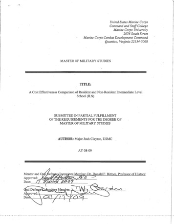
Volume 4, Issue 3, March – 2019International Journal of Innovative Science and Research TechnologyISSN No:-2456-2165 Trial 4Comparison of calculated value and simulated valueof thrust force at zero inlet flow velocitySr NoCalculatedThrust force (kN)SimulatedThrust force (kN)Trial 1Trial 2Trial 3Trial le 12:- Thrust Force AnalysisFig 22:- Total DeformationFig 23:- Von-Misses StressTotal Deformation % Difference( mm )1.98674 Trial 110.0431 Trial 26.2418.75 Trial 33.9748.3 Trial 4Table 10:- Deformation comparison with original modelFig 24:- Graph of Thrust ForceModelModelVon-Misses Equivalent% DifferenceStress ( MPa )22.9266.16 Trial 182.622 Trial 272.87.4 Trial 360.1311.23 Trial 4Table 11:- Von-Misses Equivalent Stress comparison withoriginal modelSpeed (rpm)VIII.GRAPHICAL REPRESENTATION OFMODIFIED VERSIONThe thrust force and outlet axial velocity of propelleris obtained from SolidWorks Flow Simulation 2016 withchanging rotation speed of propeller in rpm between300rpm to 1000rpm.The reason behind selecting this speed range is that,the engine of twin screw ferry passenger is 836 kW whichlies in the medium load condition. This condition generallyoperates between above speed range. Refer Table.13 &Table.14300440580Original model52.028155.068286.634Trial 169.611139.4264.757Thrust force (kN)Trial 279.488217.966402.189Trial 373.542217.164412.342Trial .6261327576.473825.6141120Table 13:- Graph of Thrust force vs SpeedIJISRT19MA410www.ijisrt.com115
Volume 4, Issue 3, March – 2019International Journal of Innovative Science and Research TechnologyISSN No:-2456-2165Fig 25:- Graph of thrust force vs speedSpeed (rpm)Outlet Axial Velocity (m/s)Original modelTrial 1Trial 2Trial 3Trial 49560.4659.964.6656.99Table 14:- Graph of Velocity vs SpeedModelMaterial Cost( Rs. )Saving( Rs. )NABCFRPOriginal1,45,5801,23,74321,837Trial 11,75,8561,49,48026,376Trial 21,31,2301,11,54519,685Trial 31,47,4571,25,33922,118Trial 41,68,1991,42,96825,231Table 15:- Cost estimationFig 26:- Graph of velocity vs speedX.IX.DISCUSSIONMATERIAL COST ESTIMATIONGenerally material used for manufacturing of marinepropeller is NAB ( Nickel Aluminium Bronze ). Accordingto present market price cost of NAB per kg is Rs. 1400while cost of per kg of CFRP is Rs. 1190.Use of CFRP ( Composite Fibre Reinforced Plastic )is very effective to reduce deformation on blade. Initially,when it was discovered it’s cost was way high but, as yearpassed by its cost has reduce. Before its implementationwas not possible because of its high price but, now it ispractical. Some material based cost analysis results arecalculated,IJISRT19MA410As per the results obtained the thrust force is maximum fortrial 4 but its mass is higher which increases the load onengine causing more fuel consumption also the velocityobtained is minimum of all model. The lowest mass is oftrial 2 with significant amount of thrust force but as peransys structural analysis deformation is greater withconsiderable high equivalent stress. The main drawback ofthis study is that no practical experimental proof is done tosupport the results obtained as the setup or manufacturingis costly at BE level. Moreover, not only material changewould provide less deformation, reduce cavitation, increaselife of blade and corrosion resistance but there is anothernewly developed method called melonite surface treatmentof metal to tackle this objectives. Future research wouldwww.ijisrt.com116
Volume 4, Issue 3, March – 2019International Journal of Innovative Science and Research TechnologyISSN No:-2456-2165include performing experimental results, advantage ofmelonite surface treatment technique over materialchanging, manufacturing and other financial cost analysis.XI.CONCLUSIONFrom the analysis of the above 5 models usingSOLIDWORKS FLOW SIMULATION 2016 and ANSYSWORKBENCH 2016 we conclude that trial 3 which is a 3blade propeller provides maximum velocity which reducestransportation time. It also provides an increased thrustforce of 73.542 kN and has comparatively less deformationthen the original model. The requirement of the twin screwferry passenger ship is heavy load and low speed so, a highthrust is required . Hence as per our analysis this is thesuitable design. screw ferry passenger ship is heavy loadand low speed so, a high thrust is required . Hence as perour analysis this is the suitable design.REFERENCES1] John Carlton Propeller materials, Marine Propeller andPropulsion, second edition, USA, 2007.2] Toshio Yam Atagi , Hideaki Murayama , Compositemarine propeller , 2011.3] HN Das, S.Kapuria , Smart composite propeller formarine applications , India , 2013.4] John Carlton Propeller performance characteristics ,Marine Propeller and Propulsion , USA , 2012.5] Dave Gerr, Propeller Handbook , 1989.6] D. Gay and S.V. Hoa, "Composite materials, Design andapplication", CRC Press, second edition, ISBN: 978-14200-4519-2, (2007).7] L.C. Burrill , calculation of marine propellerperformance characteristics , 1944.8] Prof . Dr . S . Beji , Ship Propulsion Theory. 9]Performance optimization of marine propellers Chang-SupLee1, Young-Dal Choi2, Byoung-Kwon Ahn1, MyoungSup Shin1 and Hyun-Gil Jangi , 2010.10] Design and simulation of a marine propeller T.Chittaranjan kumar reddy, k.nagaraja rao, Telangana, India, Volume 5 , issue 1 SEPT 2015.IJISRT19MA410www.ijisrt.com117
propeller. In our design we are using material for the blades which possess high tensile strength and corrosion resistance properties which enhance life of the propeller. Designing of propeller will be done using SOLIDWORKS 2016 and further structural analysis using ANSYS 2019. To compare the results between