Transcription
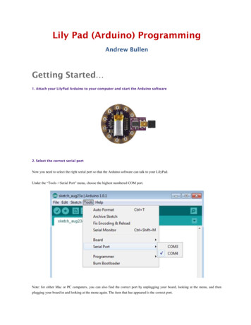
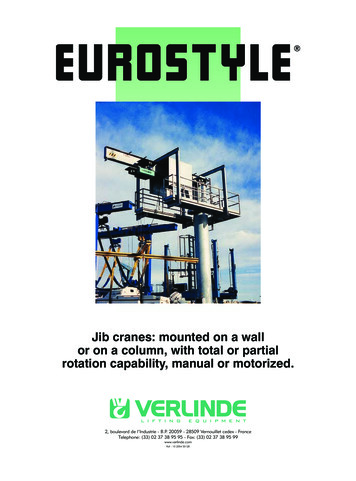
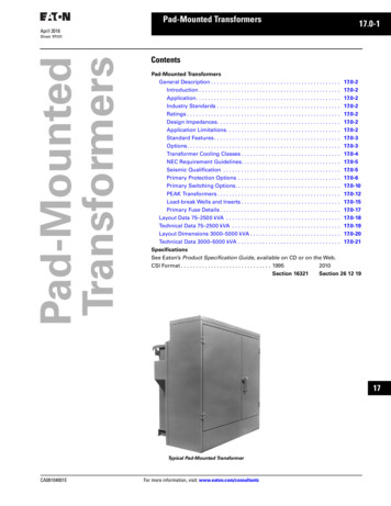
Pad-Mounted Transformers17.0-1April 2016Pad-MountedTransformersSheet 17 001ContentsPad-Mounted TransformersGeneral Description . . . . . . . . . . . . . . . . . . . . . . . . . . . . . . . . . . . . . . . . . . . 17.0-2Introduction . . . . . . . . . . . . . . . . . . . . . . . . . . . . . . . . . . . . . . . . . . . . . . . 17.0-2Application. . . . . . . . . . . . . . . . . . . . . . . . . . . . . . . . . . . . . . . . . . . . . . . . 17.0-2Industry Standards . . . . . . . . . . . . . . . . . . . . . . . . . . . . . . . . . . . . . . . . . 17.0-2Ratings . . . . . . . . . . . . . . . . . . . . . . . . . . . . . . . . . . . . . . . . . . . . . . . . . . . 17.0-2Design Impedances. . . . . . . . . . . . . . . . . . . . . . . . . . . . . . . . . . . . . . . . . 17.0-2Application Limitations. . . . . . . . . . . . . . . . . . . . . . . . . . . . . . . . . . . . . . 17.0-2Standard Features . . . . . . . . . . . . . . . . . . . . . . . . . . . . . . . . . . . . . . . . . . 17.0-3Options. . . . . . . . . . . . . . . . . . . . . . . . . . . . . . . . . . . . . . . . . . . . . . . . . . . 17.0-3Transformer Cooling Classes . . . . . . . . . . . . . . . . . . . . . . . . . . . . . . . . . 17.0-4NEC Requirement Guidelines. . . . . . . . . . . . . . . . . . . . . . . . . . . . . . . . . 17.0-5Seismic Qualification . . . . . . . . . . . . . . . . . . . . . . . . . . . . . . . . . . . . . . . 17.0-5Primary Protection Options . . . . . . . . . . . . . . . . . . . . . . . . . . . . . . . . . . 17.0-6Primary Switching Options. . . . . . . . . . . . . . . . . . . . . . . . . . . . . . . . . . . 17.0-10PEAK Transformers . . . . . . . . . . . . . . . . . . . . . . . . . . . . . . . . . . . . . . . . . 17.0-12Load-break Wells and Inserts . . . . . . . . . . . . . . . . . . . . . . . . . . . . . . . . . 17.0-15Primary Fuse Details . . . . . . . . . . . . . . . . . . . . . . . . . . . . . . . . . . . . . . . . 17.0-17Layout Data 75–2500 kVA . . . . . . . . . . . . . . . . . . . . . . . . . . . . . . . . . . . . . . 17.0-18Technical Data 75–2500 kVA . . . . . . . . . . . . . . . . . . . . . . . . . . . . . . . . . . . . 17.0-19Layout Dimensions 3000–5000 kVA . . . . . . . . . . . . . . . . . . . . . . . . . . . . . . 17.0-20Technical Data 3000–5000 kVA . . . . . . . . . . . . . . . . . . . . . . . . . . . . . . . . . . 17.0-21SpecificationsSee Eaton’s Product Specification Guide, available on CD or on the Web.CSI Format . . . . . . . . . . . . . . . . . . . . . . . . . . . . . . 19952010Section 16321Section 26 12 19iii1234567891011121314151617181920Typical Pad-Mounted TransformerCA08104001EFor more information, visit: www.eaton.com/consultants21
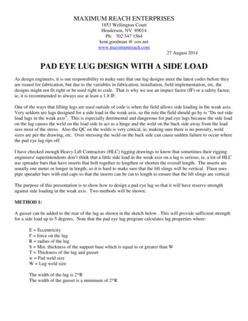
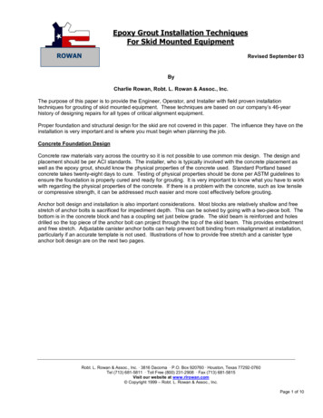
17.0-2 Pad-Mounted TransformersApril 2016Sheet 17 002General DescriptioniThree-PhasePad-Mounted TransformersiiIEEE C57.12.80, IEEE C57.12.90,IEEE C57.91, DOE 10 CFR Part 431and NEMA .Ratings 12 3 4567891011Typical Pad-Mounted TransformerIntroductionEaton’s three-phase pad-mountedtransformer is offered in a varietyof designs and configurations. Thefollowing pages describe the standarddesigns and the common options thatare available.Some special designs and options mayrequire additional engineering, factorycoordination, unusual applicationrequirements or special manufacturingneeds.13Higher impedances limit secondaryfault currents such that coordinationwith secondary low voltage moldedcase circuit breakers is usuallypossible. (Low impedances are alsoavailable if required for paralleling,and so on.)14Standard color is pad-mounted green[Munsell Green (#7GY3.29/1.5)]. ANSI#24, 61 and 70 are available as options.1215161718192021ApplicationLiquid-filled, three-phase, commercialpad-mounted distribution transformersare designed for servicing such underground distribution loads as shoppingcenters, schools, institutions, datacenters, and industrial plants. Theyare also heavily utilized for step-upapplications in renewable energyinstallations.They are available inboth deadfront and livefront andconstruction, for radial or loop-feedapplications, with or without taps.Industry StandardsPad-mounted transformers meetindustry standards: IEEE C57.12.00,IEEE C57.12.34, IEEE C57.12.28,IEEE C57.12.29, IEEE C57.12.70, 45–10,000 kVAHigh voltages (primary):4160 Grd. Y/24002400ithroughthrough43,800 GY/25,30046,000iGrd. Y/19,920HV Taps: 2–2-1/2% above and belownormal, or 4–2-1/2% below normalStandard BIL levels:kV ClassBIL (kV)1.2302.5455.0608.77515.09525.0 Grd. Y Only12525.015034.5 Grd. Y Only15034.515046250Low voltages (secondary).All voltages through 15 kV classUL listing and/or classificationavailableFactory Mutual Approval availableDesign ImpedancesImpedances are supplied to meetIEEE C57.12.34 standards. Customerspecified impedances are available.(Subject to IEEE/ANSI 7.5%impedance tolerance.) Nominal impedance perIEEE 0005.7537505.755000–10,0006.0–6.5Note: Subject to NEMA/IEEE 7.5%impedance tolerance.Note: Non-standard design impedancemay be obtained by contacting Eaton.Application LimitationsThe transformers described herein aredesigned for the application conditionsnormally encountered on electric powerdistribution systems. As such, they aresuitable for use under the “usual serviceFor more information, visit: www.eaton.com/consultantsconditions” described in IEEE StandardC57.12.00 general requirements forliquid-immersed distribution, powerand regulating transformers.Transformers required for step-upapplications should be specified as such.Consult Eaton for unusual serviceconditions such as: Abnormal environmental conditionsUnusual transient voltages presenton the source voltage Frequent or planned throughfault duty Planned overloading unless in strictaccordance with the IEEE loadingguide (C57.91) Motors whose horsepower ratingis greater than half the transformerkVA rating Unusual frequency of impact loadingmay occur when supplying weldingapparatus, electric arc furnaces ormotors with cyclical loads Loads involving abnormal harmonicor DC current that may resultwhere appreciable load currentsare controlled by solid-state orsimilar devicesThese lists do not purport to coverall unusual conditions and applicablelimitations. Other “unusual serviceconditions” are described in IEEEStandard C57.12.00. Table 17.0-1. Temperature GuaranteesDescriptionAmbient 1Rise 23StandardOptionalOptional30 C30 C30 C65 C55 C75 C 4123430 C average ambient temperature ofcooling air not to exceed 40 C maximumover any 24-hour period.Degree rise is the average windingtemperature rise by resistance.A dual temperature rating of 55 C/65 C or65 C/75 C adds 12% additional continuouscapacity to the base kVA rating of thetransformer. 55 C/75 C adds 22%.Requires transformer to be filled withEnvirotemp FR3 fluid.Note: Altitudes not to exceed 3300 ft(1006 m). Unit deration or special designsare required above 3300 ft (1006 m).Fluids—Liquid DielectricThe choice of fluid, mineral oil orless flammable natural esther fluid(Envirotemp FR3) is made basedupon site conditions and proximity tofacility walls, windows and flammablestructures, environmentally sensitiveareas, and when considering extendedtransformer insulation life.Note: For additional information abouttransformer applications and types ofinsulating fluids, see Tab 14.CA08104001E
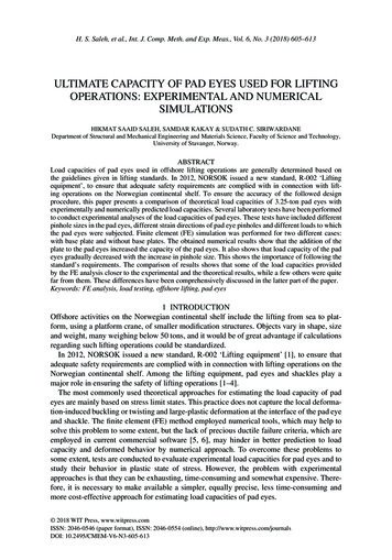
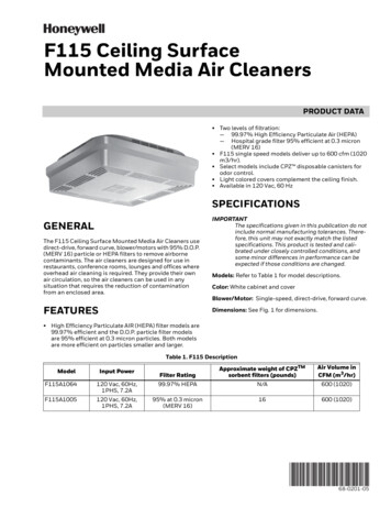
Pad-Mounted Transformers17.0-3April 2016Sheet 17 003General DescriptionStandard Featuresa Four lifting hooksb Bolted-on terminal compartmentwith removable front sillc Hinged, lift-off cabinet doorsd Interlocked penta-head bolt padlockhandle operates a cam assemblythat is part of the three-point doorlatching mechanismDeadfront construction dimensions are covered in IEEE C57.12.34. There are twoconfigurations: minimum dimensions and specific dimensions.Minimum DimensionsSpecific Dimensions Minimum bushing spacingbetween bushings Minimum bushing heights Termination compartment depthSpecific for interchangeabilitybetween manufacturers Larger dimensions than theminimum dimensions Consideration should begiven when specifying specificdimensions to make installationsand maintenance easier, and toensure adequate room for allconnections to be madePenta-head bolts must be removedfrom the flange formed on the steelhigh/low barrier before the HVdoor can be opened—not showniii1234e Tank ground pads (1 in HV, 1 in LV)(not shown)5f Steel high/low voltagecompartment barriera6g Nameplateh Fill plug and self-actuatingpressure relief device7di Externally operated no loadtap changer8j Drain valve and sampling device(not shown)9bOptions10Primary Terminationqk Removable neutral ground straprhg11l For deadfront construction, externally clamped high voltage epoxybushing wells for 200 A load-break,or 600 A non-load-break insertsm For livefront construction, externally clamped high voltage porcelain bushings double eye-bolt orspade for cable (75–225 kVA) or asingle eyebolt or spade for cable(300–1500 kVA). Spade bushingsare also offered12o13p14b15ln Parking stands16Secondary Terminationo NEMA spade terminals with supportsOptional Accessoriesp Load-break switchq Expulsion fuses, Bay-O-Netmounted with drip shieldbniPrimary and Secondary Compartment Featuress Dual primary voltage switch 1(not shown)171920Higher voltage may not exceed lowervoltage by more than 3.3:1 ratio. No tapson lower voltage.CA08104001Ec18r Liquid level gauge1fk21For more information, visit: www.eaton.com/consultants
17.0-4 Pad-Mounted TransformersApril 2016Sheet 17 004General Descriptioniii12Transformer Cooling ClassesTable 17.0-2. Fluids Advantages and DisadvantagesAdvantagesDisadvantagesMineral Oil Low transformer costGood dielectric performanceLow maintenance costGood heat dissipationGood cold climate performancePreventative maintenance—DGA historical data available Potential higher installation cost Vaults required for indoor installations per NEC due to low fire point—160 C 30% biodegradabilitySilicone Fluid345 Low heat releaseReduced smokeLow flameSelf extinguishingGood dielectric performanceLow toxicityModerate viscosityHigh stabilityNon-biodegradableNot suitable for use with internal Bay-O-Net fusesTransformer costDisposal costViton gaskets requiredRetrofil applicationsHigh transformer costHigh moisture absorptionEnvirotemp FR36789 High fire point—360 CHigh flash point—330 CCompatible with mineral oilExcellent retrofil fluid (compatible with oil up to a 7% mixtureto maintain minimum 300 C fire point) Excellent dielectric performance Greater than 99% biodegradable Greater tolerance to moisture, dramatically extending insulation lifeand therefore, transformer life Transformer cost (lower than silicone fluid) Pour point (–15 C to –25 C) transformer energized with full load with topoil temperature at –50 C with no problems—no crystals formed at –68 C Allows transformers to be designed to operate at 10 C higher averagewinding rise (75 C) without reducing normal transformer insulation life Excellent switching medium Excellent cold weather performanceTable 17.0-3. Fluid Properties ComparisonPropertyMineral OilSilicone FluidEnvirotemp FR310Specific gravityFlash point CFire point C0.911451600.963003300.9134336011Viscosity (cSt.) 100 C40 C0 C31276163890 15 5030012Pour point CDielectric strength, kVDissipation factor (%) 25 C–40300.05–55430.01 1049 0.2013PermittivityResistivityOxidation inhibitorBiodegradability2.21013Optional 30%2.71014No0%3.11013Required 99% 99%1415161718192021For more information, visit: www.eaton.com/consultantsCA08104001E
Pad-Mounted Transformers17.0-5April 2016Sheet 17 005General DescriptionNEC Requirement Guidelinesfor the Installation of ListedLess-Flammable Liquid-FilledTransformersGeneral NEC RequirementsNEC (NFPA) RecognitionRequirements for mineral oil insulatedtransformers installed outdoors arestated in NEC 450.27. In cases wherethe transformer installation presentsa fire hazard, one or more of thefollowing safeguards will be appliedaccording to the degree of hazardinvolved:These guidelines focus on therequirements of Article 450.23 ofthe National Electrical Code (NEC )for the installation of less-flammableliquid-insulated transformers. Lessflammable liquids are used intransformers where an extra marginof fire safety is important. Typicalapplications include installationsindoors, on rooftops, near buildings,in brush and forest fire prone areasand in pedestrian traffic areas.Less-flammable liquids, also known ashigh fire point liquids, are transformerdielectric coolants that have a minimum fire point of 300 C. Commonlyused less-flammable fluids includedimethysiloxane and ester-basedfluids. Two Nationally RecognizedTesting Laboratories (NRTL);Underwriters Laboratories (UL)and FM Global (FM) currentlylist less-flammable liquids. Theyalso list less-flammable liquid-filledtransformers.Less-flammable liquid-filledtransformers were formally recognizedby the NEC for indoor installationin 1978. In 1990, the NEC integratedspecific less-flammable transformerrequirements for outdoor installationsin Article 450.23, recognizing lessflammable transformers as inherentlysafer than conventional oil-filledtransformers. Less-flammabletransformers, long recognized asan additional safeguard for indoorinstallations, are becoming increasinglyrecognized for outdoor applicationsas well.transformer type, the transformersmust be marked to show the type ofinsulating liquid installed and the installations must comply with currentrequirements of the NEC. Examples ofchanges include replacing a completetransformer (retrofitting) or replacement of the liquid only (retrofilling).Askarel (PCB) and conventional mineraloil-filled transformers are frequentlyretrofitted or retrofilled using lessflammable liquids. NEC 110.34sets minimum clear work spacedimensions around transformers.The requirements and options foroutdoor installations of less-flammableliquid-insulated transfor
30.10.2012 · conditions” are described in IEEE Standard C57.12.00. Table 17.0-1. Temperature Guarantees 1 30 C average ambient temperature of cooling air not to exceed 40 C maximum over any 24-hour period. 2 Degree rise is the average winding temperature rise by resistance. 3 A dual temperature rating of 55 C/65 C or 65 C/75 C adds 12% additional continuous capacity to the base