Transcription
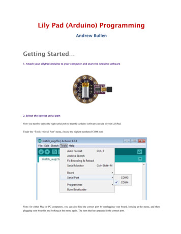
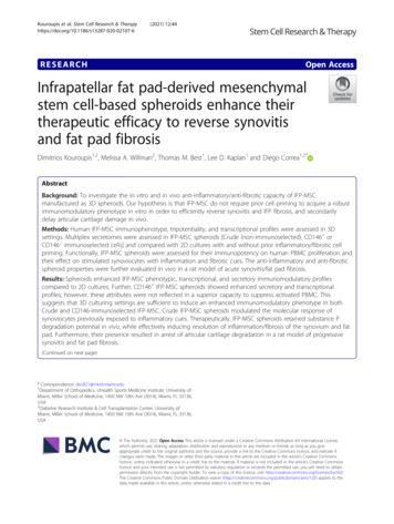
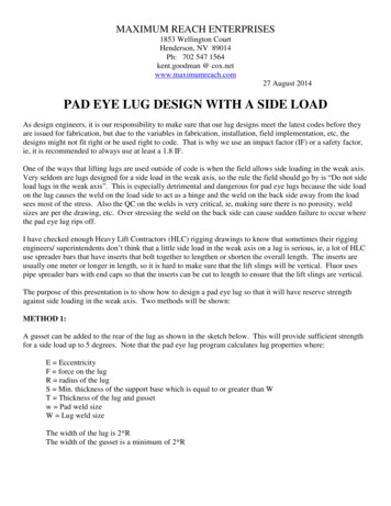
MAXIMUM REACH ENTERPRISES1853 Wellington CourtHenderson, NV 89014Ph: 702 547 1564kent.goodman @ cox.netwww.maximumreach.com27 August 2014PAD EYE LUG DESIGN WITH A SIDE LOADAs design engineers, it is our responsibility to make sure that our lug designs meet the latest codes before theyare issued for fabrication, but due to the variables in fabrication, installation, field implementation, etc, thedesigns might not fit right or be used right to code. That is why we use an impact factor (IF) or a safety factor,ie, it is recommended to always use at least a 1.8 IF.One of the ways that lifting lugs are used outside of code is when the field allows side loading in the weak axis.Very seldom are lugs designed for a side load in the weak axis, so the rule the field should go by is “Do not sideload lugs in the weak axis”. This is especially detrimental and dangerous for pad eye lugs because the side loadon the lug causes the weld on the load side to act as a hinge and the weld on the back side away from the loadsees most of the stress. Also the QC on the welds is very critical, ie, making sure there is no porosity, weldsizes are per the drawing, etc. Over stressing the weld on the back side can cause sudden failure to occur wherethe pad eye lug rips off.I have checked enough Heavy Lift Contractors (HLC) rigging drawings to know that sometimes their riggingengineers/ superintendents don’t think that a little side load in the weak axis on a lug is serious, ie, a lot of HLCuse spreader bars that have inserts that bolt together to lengthen or shorten the overall length. The inserts areusually one meter or longer in length, so it is hard to make sure that the lift slings will be vertical. Fluor usespipe spreader bars with end caps so that the inserts can be cut to length to ensure that the lift slings are vertical.The purpose of this presentation is to show how to design a pad eye lug so that it will have reserve strengthagainst side loading in the weak axis. Two methods will be shown:METHOD 1:A gusset can be added to the rear of the lug as shown in the sketch below. This will provide sufficient strengthfor a side load up to 5 degrees. Note that the pad eye lug program calculates lug properties where:E EccentricityF force on the lugR radius of the lugS Min. thickness of the support base which is equal to or greater than WT Thickness of the lug and gussetw Pad weld sizeW Lug weld sizeThe width of the lug is 2*RThe width of the gusset is a minimum of 2*R
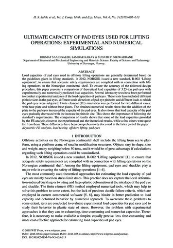
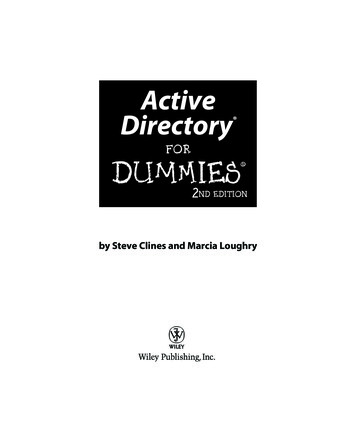
METHOD 2:A pad eye lug can be designed with some reserve strength by taking into account a side load in the weak axis.The example below shows how to calculate the stresses in the lug plate and in the weld for a 40 kips side load at10 in the weak axis.The printout below shows the design for a pad eye lug without any side load, but it is the basis for calculatingthe additional stresses that a side load imposes on the lug plate and the weld. Note the combined stress of thelug plate and the weld size are circled in the printout.
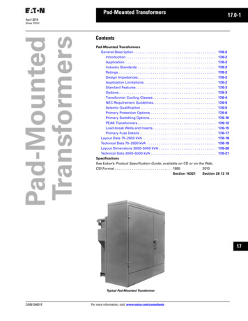
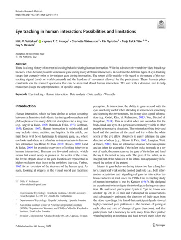
The drawing below shows the details of the pad eye lug that agrees with the printout above and also shows theside load information, ie, 40 kips at a 10 side load angle.NOW CALCULATE THE ADDITIONAL STRESS IMPOSED ON THE LUG PLATE DUE TO THESIDE LOAD:Refer to the printout and drawing above.Where:The force on the lug P at 10 deg. angleThe horizontal component of the side load force PhThe force on the lug in the strong axisThe angle of the force in the strong axis of the lugAngle of the force in the weak axisThe eccentricityThe allowable yield stress Fb in bending of the A36 plate 36 ksi*.6The allowable yield stress Ft in tension of the A36 plateThe section modulus Sx for bending in the strong axis is2” (thickness of the lug) * 7” (width of the lug) 2/6The section modulus Sz for bending in the weak axis is7” * 2 2/6Bending moment Mz in the weak axis is3.5” eccentricity *6.95 kips Ph * 1.8 (Impact factor IF)Bending stress fbz in the weak axis is43.79 k-in/4.67 cu.in.The ratio of the the bending stress fbz to the allowable bending stress is9.38/21.6 40.00 kips 6.95 kips 39.39 kips 60 deg. 10 deg. 3.5 inches 21.6 ksi 21.6 ksi 16.33 cu. in. 4.67 cu. in. 43.79 k-in. 9.38 ksi 0.43
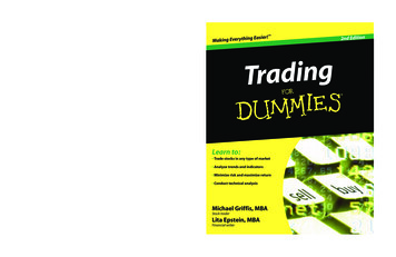
From the printout above note that the combined stress forthe lug plate without any side loadTo get the total combined stress on the lug plate in the strongaxis and the weak axis, add 0.55 0.43 0.98 1.0 0.55 GoodTherefore the lug plate is good for the 10 side loadNOW CALCULATE THE ADDITIONAL WELD REQUIRED AT THE BASE OF THE LUG PLATEDUE TO THE SIDE LOAD:Method 1:The section modulus Sz for the weld treated as a line in the weak direction is2” lug thickness * 7”lug widthBending moment in the weak axis is1.8 IF * 6.95 kips Ph * 3.5” eccentricityThe bending stress isM/Sz 43.79 k-in/14.00 sq. in. 14.00 sq. in. 43.79 k-in 3.13 k/inFrom the printout, note that the resultant force Fr on the weldwithout any side load. 12.25 k/inTherefore, the total resulting force on the weld 12.25 k/in 3.13 k/in 15.38 k/inThe minimum required weld size using an allowable force on the weld of 14.85 k/in is15.38 k/in / 14.85 k/in 1.04 inRecommend using 1 1/8” weld sizeMethod 2: My preferred method as it is usually more conservative.Calculate the vertical force F that the weld on the back side of the lug willsee due to the side load.F 43.79 k-in bending moment / 1” ( ½ width of lug) 43.79 kNow, the additional weld required due to the side load is43.79 k/(14.85 k/in*7”width of lug) 0.42Therefore the total weld size required is 0.82” (from the printout) 0.42” 1.24 inRecommend using a 1 1/4” weld sizeCOMMENTS:1.Note that the side load was taken at the center of the lug hole. If the shackle pin is a tight fit in the lughole, then the side lug force will occur up at the bail of the shackle (probably more to the side of thebail) instead of at the center of the lug hole and the eccentricity or moment arm should be taken from thebase of the lug to bearing on the shackle bail or there about, ie, for a 25 Te shackle the eccentricitywould then be /- 8.02” 3.5” /-11.52”. In this example, the additional eccentricity would overstress the lug plate and would require a very large weld size. The proof of this is left up to the reader.
2.This is why it is strongly recommended that pad eye lugs not be side loaded, because if they are it isusually hard to determine the correct moment arm to use to be conservative.END OF PAD EYE CHECK FOR A SIDE LOAD
The purpose of this presentation is to show how to design a pad eye lug so that it will have reserve strength against side loading in the weak axis. Two methods will be shown: METHOD 1: A gusset can be added to the rear of the lug as shown in the sketch below. This will provide sufficient strength for a side load up to 5 degrees. Note that the pad eye lug program calculates lug properties where:File Size: 489KBPage Count: 6