Transcription
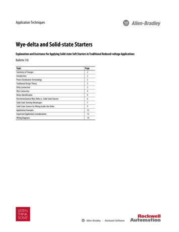
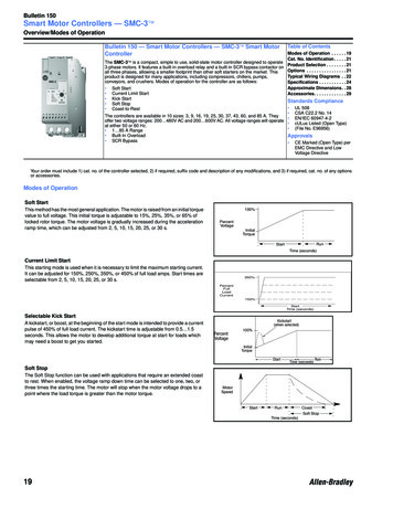
Bulletin 150Smart Motor Controllers — SMC-3 Overview/Modes of OperationBulletin 150 — Smart Motor Controllers — SMC-3 Smart MotorControllerThe SMC-3 is a compact, simple to use, solid-state motor controller designed to operate3-phase motors. It features a built-in overload relay and a built-in SCR bypass contactor onall three phases, allowing a smaller footprint than other soft starters on the market. Thisproduct is designed for many applications, including compressors, chillers, pumps,conveyors, and crushers. Modes of operation for the controller are as follows: Soft StartCurrent Limit StartKick StartSoft StopCoast-to-RestTable of ContentsModes of Operation . . . . . . 19Cat. No. Identification . . . . . 21Product Selection . . . . . . . . 21Options . . . . . . . . . . . . . . . . 21Typical Wiring Diagrams . . 22Specifications . . . . . . . . . . . 24Approximate Dimensions. . 28Accessories. . . . . . . . . . . . . 29Standards ComplianceThe controllers are available in 10 sizes: 3, 9, 16, 19, 25, 30, 37, 43, 60, and 85 A. Theyoffer two voltage ranges: 200 480V AC and 200 600V AC. All voltage ranges will operateat either 50 or 60 Hz. 1 85 A Range Built-In Overload SCR Bypass UL 508CSA C22.2 No. 14EN/IEC 60947-4-2cULus Listed (Open Type)(File No. E96956)Approvals CE Marked (Open Type) perEMC Directive and LowVoltage DirectiveYour order must include 1) cat. no. of the controller selected, 2) if required, suffix code and description of any modifications, and 3) if required, cat. no. of any optionsor accessories.Modes of OperationSoft StartThis method has the most general application. The motor is raised from an initial torquevalue to full voltage. This initial torque is adjustable to 15%, 25%, 35%, or 65% oflocked rotor torque. The motor voltage is gradually increased during the accelerationramp time, which can be adjusted from 2, 5, 10, 15, 20, 25, or 30 s.100%PercentVoltageInitialTorqueRunStartTime (seconds)Current Limit StartThis starting mode is used when it is necessary to limit the maximum starting current.It can be adjusted for 150%, 250%, 350%, or 450% of full load amps. Start times areselectable from 2, 5, 10, 15, 20, 25, or 30 s.350%PercentFullLoadCurrent150%StartTime (seconds)Selectable Kick StartA kickstart, or boost, at the beginning of the start mode is intended to provide a currentpulse of 450% of full load current. The kickstart time is adjustable from 0.5 1.5seconds. This allows the motor to develop additional torque at start for loads whichmay need a boost to get you started.Kickstart(when selected)PercentVoltage100%InitialTorqueStartTime (seconds)RunSoft StopThe Soft Stop function can be used with applications that require an extended coastto rest. When enabled, the voltage ramp down time can be selected to one, two, orthree times the starting time. The motor will stop when the motor voltage drops to apoint where the load torque is greater than the motor torque.MotorSpeedStartRunCoastSoft StopTime (seconds)19
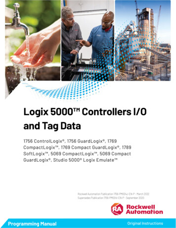
Bulletin 150Smart Motor Controllers — SMC-3 Description of Features/Cat. No. IdentificationDescription of FeaturesElectronic Motor Overload ProtectionPhase Loss/Open LoadThe SMC-3 controller incorporates, as standard, electronic motoroverload protection. This motor overload protection is accomplishedelectronically with the use of current transformers on each of the threephases. The controller’s overload protection is programmable, providingthe user with flexibility. The overload trip class selection consists of eitherOFF, 10, 15, or 20. The trip current is easily selected by adjusting therotary potentiometer to the motor full load current rating. Trip reset isselectable to either automatic or manual mode.The unit will not attempt a start if there is a single-phase condition onthe line. This protects from motor burnout during single-phase starting.Note: Trip rating is 120% of dial setting.Over-temperatureThe SMC-3 monitors the SCR temperature by means of internalthermistors. When the power poles maximum rated temperature isreached, the microcomputer switches off the SMC and a TEMP fault isindicated via LED.Phase Reversal ProtectionWhen enabled via a DIP switch, 3-phase input power will be verifiedbefore starting. If input power phasing is detected to be incorrect, thestart will be aborted and a fault indicated.Phase ImbalanceThe unit monitors for imbalance between phase currents. To preventmotor damage, the unit will trip if the phase imbalance exceeds specifiedlimits and a fault will be indicated on the LED.Shorted SCRPrior to every start, the unit will check all SCRs for shorts and unit loadconnections to the motor. If there is a shorted SCR in the SMC-3 and/or open load, the start will be aborted and a shorted SCR/open loadfault will be indicated. This prevents damage from phase imbalance.LED Description (Number of Flashes)1.2.3.4.5.6.7.OverloadOvertemperaturePhase ReversalPhase Loss/Open LoadPhase ImbalanceShorted SCRTestCat. No. ExplanationOpen and Non-Combination150–C 30 N B DBulletin Number150Solid-State ControllerControl VoltageD100 240V ACR24V AC/DCController TypeC3-WireAmpere Ratings33A99A1616 A1919 A2525 A3030 A3737 A4343 A6060 A8585 AInput Line VoltageOpen TypeB200 480V AC, 3-Phase, 50/60 HzC200 600V AC, 3-Phase, 50/60 HzEnclosure TypeNOpenSpecifications — Page 21Approximate Dimensions — Page 2820
Bulletin 150Smart Motor Controllers — SMC-3 Product SelectionOpen Type ControllersUp to 480V ACkWHp380/400/415V AC50 Hz230V AC50 HzCurrentRating (A)➊200V AC60 Hz230V AC60 Hz460V AC60 HzStarting Duty350%450%350%450%350%450%350%450%350%450%1 30.550.371.10.750.50.50.50.50.5 1.50.5 13 92.21.5430.75 20.75 1.50.75 20.75 21.5 51.5 35.3 16437.55.51.5 31.5 31.5 51.5 35 105 7.56.3 19447.55.51.5 51.5 32 52 35 105 108.3 255.54119.53 7.53 53 7.53 57.5 157.5 1010 307.55.515113 7.53 55 105 7.57.5 207.5 1512.3 377.57.518.5155 105 7.55 105 1010 2510 2014.3 43117.522155 105 7.55 155 1010 3010 2020 60151130227.5 157.5 107.5 207.5 1515 4015 3028.3 852218.5453710 2510 2015 3015 2025 6025 50100 240V AC50/60 HzControlCat. No.24V AC/DCControlCat. p to 600V ACCurrentRating(A)➊1 33 95.3 166.3 198.3 2510 3012.3 3714.3 4320 6028.3 85230V AC50 HzkW380/400/415VAC50 HzHp500V AC50 Hz200V AC60 Hz230V AC60 Hz460V AC60 Hz575V AC60 Hz100 240V AC50/60 HzControlCat. No.24V AC/DCControlCat. tarting 55.59.51115152237350%1.55.57.5111518.522223755450% 350%450%350%450%350%450%350%450%1.10.50.50.50.50.5 1.5 0.5 1 0.75 2 0.75 140.75 2 0.75 1.5 0.75 2 0.75 2 1.5 51.5 3 3 7.53 57.51.5 31.5 31.5 5 1.5 35 105 7.5 5 105 107.51.5 51.5 32 52 35 105 10 7.5 15 7.5 10113 7.53 53 7.53 57.5 15 7.5 10 7.5 20 7.5 15153 7.53 55 10 5 7.5 7.5 20 7.5 15 10 25 10 2018.55 105 7.55 105 1010 25 10 20 15 30 15 25225 105 7.55 155 1010 30 10 20 15 40 15 30377.5 15 7.5 10 7.5 20 7.5 15 15 40 15 30 20 50 20 404510 2510 2015 30 15 20 25 60 25 50 30 75 30 60➊ Motor FLA must fall within the current range of the device.Specifications — Page 24Approximate Dimensions — Page 2821
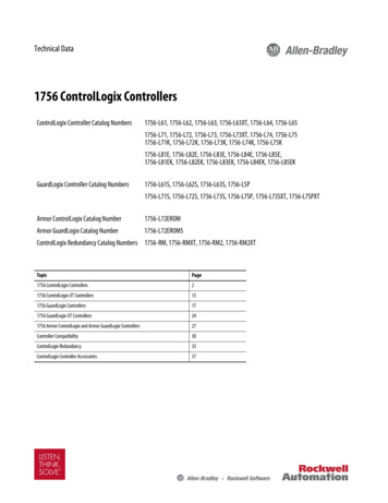
Bulletin 150Smart Motor Controllers — SMC-3 Typical Wiring DiagramsTwo-Wire ConfigurationIECNEMAThree-Wire ConfigurationIEC22NEMA
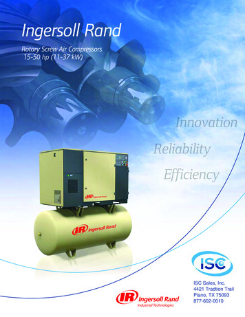
Bulletin 150Smart Motor Controllers — SMC-3 Typical Wiring Diagrams, ContinuedIsolation Contactor ConfigurationIECNEMAReversing ConfigurationNote: Minimum Off time equals 1.0 s.IECNEMA23
Bulletin 150Smart Motor Controllers — SMC-3 SpecificationsCat. No.Rated operating current Ie (A)Heat dissipation (W)Rated operating voltageC33Continuous11Electrical Ratings Cat. Nos. 150- 51924345082200 480, 200 600V AC 50/60 Hz, 3-phase ( 10%, -15%)Cable size:2.5 25 mm2 (14 4 AWG)2.5 95 mm2 (14 3/0 AWG)Line Power terminalsTightening torque:2.3 3.4 N m (20 30 in-lbs)11.3 12.4 N m (100 110 in-lbs)Cable size:2.5 50 mm2 (14 1 AWG)2.5 16 mm2 (14 6 AWG)Load Power terminalsTightening torque:2.3 3.4 N m (20 30 in-lbs)11.3 12.4 N m (100 110 in-lbs)Cable size:0.2 2.5 mm2 (24 14 AWG)Control terminalsTightening torque:0.5 0.9 N m (4.4 8.0 in-lbs)Maximum continuous current3A9A16 A19 A25 A30 A37 A43 A60 A85 AOverload current range (A)1 33 95.3 16 6.3 19 8.3 25 10 30 12.3 37 14.3 4320 6028.3 85Control Voltage Requirements100 240V AC or 24V AC/DC 50/60 HzShort Circuit Coordination (Max Fuse or Circuit Breaker Size) Type 15 kA Available Fault CurrentUL Class K5 and RK5 FusesUL Listed Combination (600V)10 A35 A60 A70 A100 A110 A125 A150 A——10 kA Available Fault CurrentUL Class K5 and RK5 FusesUL Listed Combination (600V)————————225 A300 A5 kA Available Fault CurrentUL Listed Thermal Magnetic Circuit BreakerUL Listed Combination (600V)15 A35 A60 A70 A100 A110 A125 A150 A——10 kA Available Fault CurrentUL Listed Thermal Magnetic Circuit BreakerUL Listed Combination (600V)————————225 A300 A5 kA Available Fault CurrentUL Listed Bulletin 140M Motor Protection C.B.UL Listed Combination (600V)C25C25F45F45F45F45F45———Power CircuitUL/cULIEC200 480V AC200 480V — 400V Rated operational voltage200 600V AC500V — 500V Rated insulation voltage600V AC500V Dielectric withstand2200V AC2500V 200 480V AC — 1400V200 480V — 1400VRepetitive peak200 600V AC — 1600V500V — 1600VOperating frequency50/60 Hz50/60 HzUtilization categoryIntermittent dutyAC-53bNumber of polesEquipment designed for 3-phase onlyRated impulse voltage6 kVDV/DT protection1000V/µsOvervoltage categoryIIIIII24
Bulletin 150Smart Motor Controllers — SMC-3 Specifications, ContinuedControl CircuitUL/cUL100 240V AC, 24V AC/DC250V—1500V AC—50/60 HzRated operational voltage ( 10%, –15%)Rated insulation voltageRated impulse voltageDielectric withstandOvervoltage categoryOperating frequencyInput onstate voltage minimum (IN1, IN2)85V AC, 19.2V DC / 13.5V ACInput onstate current (IN1, IN2)9.8 mA @ 120V AC / 19.6mA @ 240V AC, 7.3 mA @ 24V AC/DCInput offstate voltage maximum (IN1, IN2)40V AC, 17V DC / 12V ACInput offstate current @ input offstate voltage(IN1, IN2)Control power with fan, during startControl power without fan, during start 10 mA, 12 mA3 37 A215 mA @ 120V AC / 180 mA @ 240V AC, 800 mA @ 24V DC / 660 mA @ 24V AC43 85 A200 mA @ 120V AC / 100 mA @ 240V AC, 700 mA @ 24V AC/DC3 37 A205 mA @ 120V AC / 145 mA @ 240V AC, 705 mA @ 24V DC / 580 mA @ 24V ACAuxiliary ContactsUL/cUL250V AC / 30V DC250V—1500V AC—50/60 HzD300Rated operational voltageRated insulation voltageRated impulse voltageDielectric withstandOvervoltage categoryOperating frequencyUtilization categoryTB-97, -98 (OVLD/Fault)Type of control circuitNumber of contactsType of contactsKind of currentRated operationalcurrent (max.)Conventionalthermal current IthIEC250V / 30V DC250V 4 kV2000V III ➊50/60 HzAC15Electromagnetic relay1Normally Open (N.O.)AC/DC0.6 A @ 120V and 0.3 A @ 240V 1AMake VA/break VATB-13, -14 (Normal/Up-to-Speed)IEC100 240V , 24V AC/DC250V 4 kV2000V III ➊50/60 Hz432/72Type of control circuitNumber of contactsType of contactsKind of currentRated operationalcurrent (max.)Conventionalthermal current IthElectromagnetic relay1Normally Open (N.O.)AC/DC0.6 A @ 120V and 0.3 A @ 240V 1AMake VA/break VA432/72Standard FeaturesStart timesSelectable soft startSelectable current limitSelectable soft stopWeight — kg (lbs)Resistance to vibrationResistance to shock2, 5, 10, or 15 s15%, 25%, 35%, and 65% of locked rotor torque150%, 250%, 350%, and 450% of full load current100%, 200%, or 300% of the start time setting when wired1 37 A0.86 (1.9)43 85 A2.25 (5)Mechanical Design Specifications/Test Requirements1.0 G peak, 0.152 mm (0.006 in.) displacementOperationalNon-operational2.5 G peak, 0.381 mm (0.015 in.) displacementOperational15 GNon-operational30 G➊ Overvoltage category II, when either control or auxiliary circuit is wired to a SELV or PELV circuit.25
Bulletin 150Smart Motor Controllers — SMC-3 Specifications, ContinuedEnviroN mental0 50 C (32 122 F) (open)0 40 C (32 104 F) (enclosed)-25 85 C (-13 185 F)2000 m (6560 ft)5 95% (non-condensing)2IP2XOperating temperatureStorage temperatureAltitudeHumidityPollution degreeType of ucted radio frequency emissionsRadiated emissionsElectrostatic dischargeRadio frequency electromagnetic fieldFast transientSurge transientOtherUL/cUL—IECClass A—Class A4 kV contact and 8kV air discharge———Per IEC 60947-4-2Per IEC 60947-4-2Per IEC 60947-4-2
Bulletin 150Smart Motor Controllers — SMC-3 Trip CurvesSMC-3 Overload RelaysTrip Class 10Trip Class 15Cold TripTrip Class 20Cold TripHot TripHot Trip100100Cold Trip1000Hot Trip100t (sec)t (sec)t %10CurrentStarts per Hour CurvesSMC-3 Starts per hour40C,100% Duty Cycle, 10sec, 350% with FanSMC-3 Starts per hour40C, 100 % duty cycle 10sec, 350%, No Fan6014050120100Starts / HourStarts / Hour40302060401020000 5 10 15 20 25 30 35 400 5 10 15 20 25 30 35 40Current (amps)Current C25,C30,C37150-C25,C30,C372780100%11000%10Current
Bulletin 150Smart Motor Controllers — SMC -3Approximate DimensionsDimensions in millimeters (inches). Dimensions are not intended to be used for manufacturing purposes. All dimensions are subject tochange.Open TypeRating (A)ABCDEFGMountingHole SizeWeightkg (lbs)1 3744.8 (1-49/64)139.7 (5-1/2)100 (4-21/64)35 (1-3/8)132 (5-13/64)46.4 (1.81)2 (1/16)4.6 (0.18)0.86 (1.9)43 8572 (2.83)206 (8.11)130 (5.12)55 (2.17)198 (7.8)102 (4.02)2 (1/16)5.3 (0.21)2.25 (5.0)108 135196.4 (7.74)443.7 (17.47)205.2 (8.08)166.6 (6.56)367 (14.45) 7.5 (0.295)15 (33)201 251225 (8.86)560 (22.05)265.3 (10.45)150 (5.91)504.1 (19.85) 11.5 (0.45)30.4 (67)317 480290 (11.42)600 (23.62)298 (11.73)200 (7.87)539.2 (21.23) 11.5 (0.45)45.8 (101)Minimum Enclosure SizeControllerA WidthB HeightC Depth1 37 A224 (9)305 (12)152 (6)none43 85 A406 (16)305 (12)203 (8)none108 135 A762 (30)610 (24)305 (12)none201 251 A965 (38)762 (30)356 (14)none317 480 A1295 (51)914 (36)356 (14)noneVisit our website: www.ab.com/catalogsFan Requirements
Bulletin 150Smart Motor Controllers — SMC -3Approximate Dimensions, ContinuedEnclosed Type Line-Connected ControllersControllerRating (A)IP65 (Type 4/12)Disconnect Rating (A)B HeightA WidthC DepthNon-Combination Controller3—305 (12)305 (12)152 (6)9—305 (12)305 (12)152 (6)16—305 (12)305 (12)152 (6)25—305 (12)305 (12)152 (6)30—305 (12)305 (12)152 (6)37—305 (12)305 (12)152 (6)43—356 (14)406 (16)203 (8)60—356 (14)406 (16)203 (8)85—356 (14)406 (16)203 (8)108—762 (30)610 (24)305 (12)135—762 (30)610 (24)305 (12)201—965 (38)762 (30)356 (14)251—965 (38)762 (30)356 (14)317—1295 (51)914 (36)356 (14)361—1295 (51)914 (36)356 (14)480—1295 (51)914 (36)356 (14)Combination Controllers with Fusible Disconnect330 A/J356 (14)406 (16)203 (8)930 A/J356 (14)406 (16)203 (8)1630 A/J356 (14)406 (16)203 (8)2530 A/J356 (14)406 (16)203 (8)3060 A/J356 (14)406 (16)203 (8)3760 A/J356 (14)406 (16)203 (8)4360 A/J356 (14)406 (16)203 (8)60100 A/J610 (24)406 (16)254 (10)859100 A/J610 (24)406 (16)254 (10)857100 A/J762 (30)610 (24)305 (12)108200 A/J965 (38)762 (30)356 (14)135200 A/J965 (38)762 (30)356 (14)201400 A/J965 (38)762 (30)356 (14)251400 A/J965 (38)762 (30)356 (14)317600 A/J1524 (60)965 (38)356 (14)361600 A/J1524 (60)965 (38)356 (14)480600 A/J1524 (60)965 (38)356 (14)Combination Controllers with Circuit Breaker315 A356 (14)406 (16)203 (8)915 A356 (14)406 (16)203 (8)1620 A356 (14)406 (16)203 (8)2530 A356 (14)406 (16)203 (8)3040 A356 (14)406 (16)203 (8)3750 A356 (14)406 (16)203 (8)4380 A610 (24)406 (16)254 (10)60100 A610 (24)406 (16)254 (10)85125 A610 (24)406 (16)254 (10)108175 A/175 A Plug965 (38)762 (30)356 (14)135225 A/225 A Plug965 (38)762 (30)356 (14)201300 A/300 A Plug965 (38)762 (30)356 (14)251400 A/400 A Plug965 (38)762 (30)356 (14)317600 A/600 A Plug1295 (51)914 (36)356 (14)361600 A/600 A Plug1295 (51)914 (36)356 (14)480800 A/800 A Plug1295 (51)914 (36)356 (14)9 Dimensions for FHD-43, FAD-44, FBD-47, and FCD-48.7 Dimensions for FHD-44, FAD-45, FBD-48, and FCD-49Visit our website: www.ab.com/catalogs
The SMC-3 is a compact, simple to use, solid-state motor controller designed to operate 3-phase motors. It features a built-in overload relay and a built-in SCR bypasscontactor on all three phases, allowing a smaller footprint than other soft starters on the market. This product is designed for many applications, including compressors, chillers.