Transcription
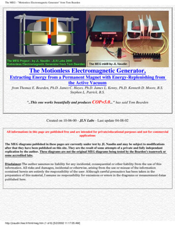
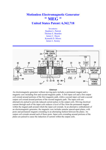
Motionless Electromagnetic Generator" MEG "United States Patent: 6,362,718Inventors:Stephen L. PatrickThomas E. BeardenJames C. HayesKenneth D. MooreJames L. KennyAbstractAn electromagnetic generator without moving parts includes a permanent magnet and amagnetic core including first and second magnetic paths. A first input coil and a first outputcoil extend around portions of the first magnetic path, while a second input coil and a secondoutput coil extend around portions of the second magnetic path. The input coils arealternatively pulsed to provide induced current pulses in the output coils. Driving electricalcurrent through each of the input coils reduces a level of flux from the permanent magnetwithin the magnet path around which the input coil extends. In an alternative embodiment ofan electromagnetic generator, the magnetic core includes annular spaced-apart plates, withposts and permanent magnets extending in an alternating fashion between the plates. Anoutput coil extends around each of these posts. Input coils extending around portions of theplates are pulsed to cause the induction of current within the output coils.
BACKGROUND INFORMATION1. Field of InventionThis invention relates to a magnetic generator used to produce electrical power withoutmoving parts, and, more particularly, to such a device having a capability, when operating, ofproducing electrical power without an external application of input power through input coils.2. Description of the Related ArtThe patent literature describes a number of magnetic generators, each of which includes apermanent magnet, two magnetic paths external to the permanent magnet, each of whichextends between the opposite poles of the permanent magnet, switching means for causingmagnetic flux to flow alternately along each of the two magnetic paths, and one or moreoutput coils in which current is induced to flow by means of changes in the magnetic fieldwithin the device. These devices operate in accordance with an extension of Faraday's Law,indicating that an electrical current is induced within a conductor within a changing magneticfield, even if the source of the magnetic field is stationary.A method for switching magnetic flux to flow predominantly along either of two magneticpaths between opposite poles of a permanent magnet is described as a "flux transfer" principleby R. J. Radus in Engineer's Digest, Jul. 23, 1963. This principle is used to exert a powerfulmagnetic force at one end of both the north and south poles and a very low force at the otherend, without being used in the construction of a magnetic generator. This effect can be causedmechanically, by keeper movement, or electrically, by driving electrical current through oneor more control windings extending around elongated versions of the pole pieces 14. Severaldevices using this effect are described in U.S. Pat. Nos. 3,165,723, 3,228,013, and 3,316,514,which are incorporated herein by reference.Another step toward the development of a magnetic generator is described in U.S. Pat. No.3,368,141, which is incorporated herein by reference, as a device including a permanentmagnet in combination with a transformer having first and second windings about a core, withtwo paths for magnetic flux leading from each pole of the permanent magnet to either end ofthe core, so that, when an alternating current induces magnetic flux direction changes in thecore, the magnetic flux from the permanent magnet is automatically directed through the pathwhich corresponds with the direction taken by the magnetic flux through the core due to thecurrent. In this way, the magnetic flux is intensified. This device can be used to improve thepower factor of a typically inductively loaded alternating current circuit.Other patents describe magnetic generators in which electrical current from one or moreoutput coils is described as being made available to drive a load, in the more conventionalmanner of a generator. For example, U.S. Pat. No. 4,006,401, which is incorporated herein byreference, describes an electromagnetic generator including permanent magnet and a coremember, in which the magnetic flux flowing from the magnet in the core member is rapidlyalternated by switching to generate an alternating current in a winding on the core member.The device includes a permanent magnet and two separate magnetic flux circuit pathsbetween the north and south poles of the magnet. Each of the circuit paths includes twoswitching means for alternately opening and closing the circuit paths, generating analternating current in a winding on the core member. Each of the switching means includes aswitching magnetic circuit intersecting the circuit path, with the switching magnetic circuit
having a coil through which current is driven to induce magnetic flux to saturate the circuitpath extending to the permanent magnet. Power to drive these coils is derived directly fromthe output of a continuously applied alternating current source. What is needed is anelectromagnetic generator not requiring the application of such a current source.U.S. Pat. No. 4,077,001, which is incorporated herein by reference, describes a magneticgenerator, or dc/dc converter, comprising a permanent magnet having spaced-apart poles anda permanent magnetic field extending between the poles of the magnet. A variable-reluctancecore is disposed in the field in fixed relation to the magnet and the reluctance of the core isvaried to cause the pattern of lines of force of the magnetic field to shift. An output conductoris disposed in the field in fixed relation to the magnet and is positioned to be cut by theshifting lines of permanent magnetic force so that a voltage is induced in the conductor. Themagnetic flux is switched between alternate paths by means of switching coils extendingaround portions of the core, with the flow of current being alternated between these switchingcoils by means of a pair of transistors driven by the outputs of a flip-flop. The input to the flipflop is driven by an adjustable frequency oscillator. Power for this drive circuit is suppliedthrough an additional, separate power source. What is needed is a magnetic generator notrequiring the application of such a power source.U.S. Pat. No. 4,904,926, which is incorporated herein by reference, describes anothermagnetic generator using the motion of a magnetic field. The device includes an electricalwinding defining a magnetically conductive zone having bases at each end, the windingincluding elements for the removing of an induced current therefrom. The generator furtherincludes two pole magnets, each having a first and a second pole, each first pole in magneticcommunication with one base of the magnetically conductive zone. The generator furtherincludes a third pole magnet, the third pole magnet oriented intermediately of the first poles ofthe two pole electromagnets, the third pole magnet having a magnetic axis substantiallytransverse to an axis of the magnetically conductive zone, the third magnet having a polenearest to the conductive zone and in magnetic attractive relationship to the first poles of thetwo pole electromagnets, in which the first poles thereof are like poles. Also included in thegenerator are elements, in the form of windings, for cyclically reversing the magneticpolarities of the electromagnets. These reversing means, through a cyclical change in themagnetic polarities of the electromagnets, cause the magnetic flux lines associated with themagnetic attractive relationship between the first poles of the electromagnets and the nearestpole of the third magnet to correspondingly reverse, causing a wiping effect across themagnetically conductive zone, as lines of magnetic flux swing between respective first polesof the two electromagnets, thereby inducing electron movement within the output windingsand thus generating a flow of current within the output windings.U.S. Pat. No. 5,221,892, which is incorporated herein by reference, describes a magneticgenerator in the form of a direct current flux compression transformer including a magneticenvelope having poles defining a magnetic axis and characterized by a pattern of magneticflux lines in polar symmetry about the axis. The magnetic flux lines are spatially displacedrelative to the magnetic envelope using control elements which are mechanically stationaryrelative to the core. Further provided are inductive elements which are also mechanicallystationary relative to the magnetic envelope. Spatial displacement of the flux relative to theinductive elements causes a flow of electrical current. Further provided are magnetic fluxvalves which provide for the varying of the magnetic reluctance to create a time domainpattern of respectively enhanced and decreased magnetic reluctance across the magneticvalves, and, thereby, across the inductive elements.
Other patents describe devices using superconductive elements to cause movement of themagnetic flux. These devices operate in accordance with the Meissner effect, which describesthe expulsion of magnetic flux from the interior of a superconducting structure as the structureundergoes the transition to a superconducting phase. For example, U.S. Pat. No. 5,011,821,which is incorporated herein by reference, describes an electric power generating deviceincluding a bundle of conductors which are placed in a magnetic field generated by north andsouth pole pieces of a permanent magnet. The magnetic field is shifted back and forth throughthe bundle of conductors by a pair of thin films of superconductive material. One of the thinfilms is placed in the superconducting state while the other thin film is in a nonsuperconducting state. As the states are cyclically reversed between the two films, themagnetic field is deflected back and forth through the bundle of conductors.U.S. Pat. No. 5,327,015, which is incorporated herein by reference, describes an apparatus forproducing an electrical impulse comprising a tube made of superconducting material, a sourceof magnetic flux mounted about one end of the tube, a means, such as a coil, for interceptingthe flux mounted along the tube, and a means for changing the temperature of thesuperconductor mounted about the tube. As the tube is progressively made superconducting,the magnetic field is trapped within the tube, creating an electrical impulse in the means forintercepting. A reversal of the superconducting state produces a second pulse.None of the patented devices described above use a portion of the electrical power generatedwithin the device to power the reversing means used to change the path of magnetic flux.Thus, like conventional rotary generators, these devices require a steady input of power,which may be in the form of electrical power driving the reversing means of one of thesemagnetic generators or the torque driving the rotor of a conventional rotary generator. Yet, theessential function of the magnetic portion of an electrical generator is simply to switchmagnetic fields in accordance with precise timing. In most conventional applications ofmagnetic generators, the voltage is switched across coils, creating magnetic fields in the coilswhich are used to override the fields of permanent magnets, so that a substantial amount ofpower must be furnished to the generator to power the switching means, reducing theefficiency of the generator.Recent advances in magnetic material, which have particularly been described by Robert C.O'Handley in Modern Magnetic Materials, Principles and Applications, John Wiley & Sons,New York, pp. 456-468, provide nanocrystalline magnetic alloys, which are particularly wellsuited forth rapid switching of magnetic flux. These alloys are primarily composed ofcrystalline grains, or crystallites, each of which has at least one dimension of a fewnanometers. Nanocrystalline materials may be made by heat-treating amorphous alloys whichform precursors for the nanocrystalline materials, to which insoluble elements, such ascopper, are added to promote massive nucleation, and to which stable, refractory alloyingmaterials, such as niobium or tantalum carbide are added to inhibit grain growth. Most of thevolume of nanocrystalline alloys is composed of randomly distributed crystallites havingdimensions of about 2-40 nm. These crystallites are nucleated and grown from an amorphousphase, with insoluble elements being rejected during the process of crystallite growth. Inmagnetic terms, each crystallite is a single-domain particle. The remaining volume ofnanocrystalline alloys is made up of an amorphous phase in the form of grain boundarieshaving a thickness of about 1 nm.Magnetic materials having particularly useful properties are formed from an amorphous Co--
Nb--B (cobalt-niobium-boron) alloy having near-zero magnetostriction and relatively strongmagnetization, as well as good mechanical strength and corrosion resistance. A process ofannealing this material can be varied to change the size of crystallites formed in the material,with a resulting strong effect on DC coercivity. The precipitation of nanocrystallites alsoenhances AC performance of the otherwise amorphous alloys.Other magnetic materials are formed using iron-rich amorphous and nanocrystalline alloys,which generally show larger magnetization that the alloys based on cobalt. Such materials are,for example, Fe--B--Si--Nb--Cu (iron-boron-silicon-niobium-copper) alloys. While thepermeability of iron-rich amorphous alloys is limited by their relatively large levels ofmagnetostriction, the formation of a nanocrystalline material from such an amorphous alloydramatically reduces this level of magnetostriction, favoring easy magnetization.Advances have also been made in the development of materials for permanent magnets,particularly in the development of materials including rare earth elements. Such materialsinclude samarium cobalt, SmCo.sub.5, which is used to form a permanent magnet materialhaving the
Motionless Electromagnetic Generator " MEG " United States Patent: 6,362,718 Inventors: Stephen L. Patrick Thomas E. Bearden James C. Hayes Kenneth D. Moore James L. Kenny Abstract An electromagnetic generator without moving parts includes a permanent magnet and a magnetic core including first and second magnetic paths. A first input coil and a first output coil extend around