Transcription
Application TechniquesWye-delta and Solid-state StartersExplanation and Assistance for Applying Solid-state Soft Starters in Traditional Reduced-voltage ApplicationsBulletin 150TopicSummary of ChangesIntroductionPower Distribution TerminologyTraditional Design TheoryDelta ConnectionWye ConnectionMotor IdentificationElectromechanical Wye-Delta vs. Solid-State StartersSolid-State Starting AdvantagesSolid-State Starters for Wiring Inside-the-DeltaApplication ExamplesImportant Application ConsiderationsWiring DiagramsPage2223344679121314
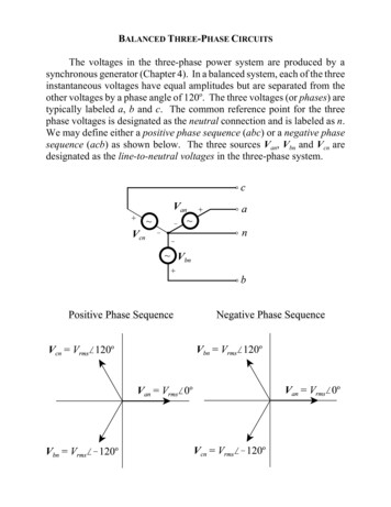
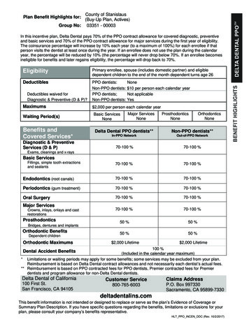
Wye-delta and Solid-state StartersSummary of ChangesThis publication removes references to the SMC Delta soft starter and replaces it with the SMC-50 soft starter.IntroductionThe theory of applying reduced voltage to a motor to alter the motor torque and power consumption characteristics hasexisted for many years. These concepts have flourished due to the need to limit torque and limited generator/powerdistribution capabilities. Energy conservation initiatives have forced local governments to place mandatory reducedvoltage starting requirements on motors rated at 7.5 Hp (5.5 kW) and larger.You can accomplish reduced-voltage starting through various methods, including part winding, wound rotor, autotransformer, wye-delta, or solid-state. While many of these techniques require specialty motors or special systemcomponents, the wye-delta and solid-state methods are the simplest to apply. Applications that are used in the UnitedStates differ, but over the years the dominant method worldwide has been the wye-delta or star-delta starting technique.The latest generation of soft starters and Smart Motor Controllers (SMCs) offers significant advantages over itspredecessors when it comes to using it in wye-delta applications. In most cases, you can use these solid-state products toreplace or retrofit any of the traditional reduced-voltage methods. We have designed the SMC product line to take fulladvantage of solid-state technology and advanced features. This design allows the controller to provide a cost-effectivemodular solution to both new and existing reduced-voltage applications.Power Distribution TerminologyApproximately 75% of global power systems are supplied as wye power from the transformer. Whether the power issupplied as wye or delta makes little difference to the system starter components, provided there is an appropriate voltagepotential and phase relationship present. Figure 1 illustrates a simple connection scheme of the incoming utility powerthrough the motor. Remember that there are many different configurations throughout the world, but a wye-configuredsystem operating at 380 415V is the most common. In the United States, both wye and delta power systems are used,and range from 240 480V AC.When we use the term “wye-delta motor configuration” in this document, we are referencing how the motor windingsare connected to the power system. As we discuss, the physical connection of these windings has an effect on the actualapplied voltage to the windings, regardless of the power configuration from the transformer.2Rockwell Automation Publication 150-AT005A-EN-P - July 2016
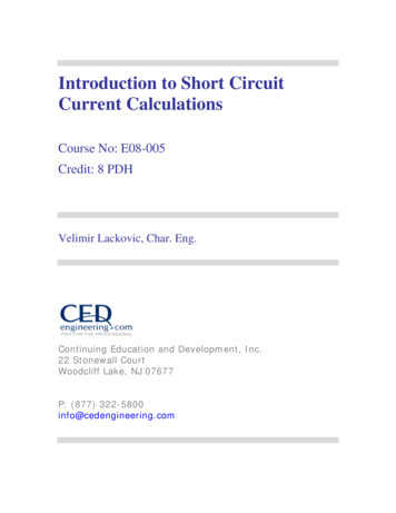
Wye-delta and Solid-state StartersFigure 1 - Simple System Line Diagram—Wye-connected Power Transformer and Delta-connected MotorTransformer480M3 480Y12470 L-L7200 L-NY480 L-L277 L-NDistribution TransformerOLShort-circuitProtective DeviceMotor ControllerTraditional Design TheoryBy definition, wye-delta is a traditional electromechanical method of reducing the voltage applied to the motor duringstarting. This method has significant advantages over conventional full-voltage starting; the disadvantage is that itrequires more panel space, more components, and, most importantly, a motor that has all its winding terminationsavailable to the outside so that you can create the wye connection.While we use the term “reduced-voltage starter” for the wye-delta starting method, the full line voltage is still beingapplied to the motor leads. The reduced voltage occurs because of the electrical characteristic of the wye vs. deltarelationship.Delta ConnectionThe delta configuration shown in Figure 2 shows the resulting applied voltage on a delta connection. The deltaconnection is the most common way a motor is connected for direct-on-line, full-voltage starting. The motor windingsare designed to operate at the nominal full-voltage rating, which is 400V outside the United States or 480V within theU.S.Figure 2 - Voltage on Delta Connection400Vor480V400Vor480V400V or 480VRockwell Automation Publication 150-AT005A-EN-P - July 20163
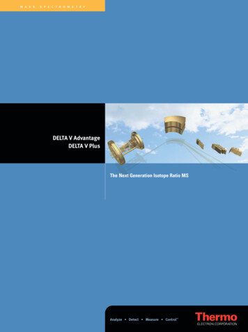
Wye-delta and Solid-state StartersAs an example let's examine the electrical characteristics of a 15 kW/20 Hp 1800 RPM motor. The full load current isapproximately 30 A at 400V or 26 A at 480V. If we assume that the nominal starting current is 600% of full load current,then the resulting inrush current during starting is about 180 A/156 A respectively. The resulting starting torque wouldbe 100% of the motor nominal full-load torque.Wye ConnectionWith the windings in a wye connection, the full voltage applied line to line is the same as a delta configuration, but thevoltage across the individual motor windings is reduced as shown in Figure 3. The voltage is reduced by the inverse of thesquare root of 3 or 57.7% of full voltage.1 480V 480x 480 (0.577) x 480 277VStarting Voltage Reduction ------------- ---------- 1.731.73 3For power systems with a Line to Line (L to L) voltage of 400V or 480V, the actual voltage across the motor windings isthe Line to Neutral (L to N) voltage of 230V or 277V, respectively.Figure 3 - Voltage on Wye Connection400 or 480 VoltsLine to LineNeutral230 or 277 VoltsLine to NeutralThe effect of applying reduced voltage across the windings during starting can be explained by our example. With thewye connection, the starting current is proportional to the voltage reduction, therefore:LRA 156 Starting Current Reduction x 57.7% x 57.7% 51 A 1.73 1.73 Using the information (LRA 180 A/156 A), the wye connection current would be approximately 60 A for 400V or51 A for 480V. It is easy to notice the large reduction in current. However, the result of the reduced voltage also meansthat some starting torque is sacrificed. The reduction in torque would be approximately equal to the square of thereduction of voltage across the motor windings, or:22Starting Torque Reduction (%V ) (.577 ) x 100% 33% of full load torqueMotor IdentificationWhether the application is new or existing, it can be easy to identify wye-delta connected motors. The motor nameplateand connection diagram typically indicate wye-delta or star-delta, but there may also be references to low volts and highvolts. The most common voltage combinations are 220/380V AC and 277/480V AC.A single-voltage wye-delta motor typically has six leads that are marked T-1 through T-6. In comparison, a standardsingle-voltage delta motor has three leads that are marked T-1 through T-3. For dual-voltage motors, the wye-delta motor4Rockwell Automation Publication 150-AT005A-EN-P - July 2016
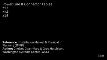
Wye-delta and Solid-state Startershas12 leads marked T-1 through T-12; the standard delta motor has nine leads that are marked T-1 through T-9. Figure 4shows two common connection diagrams for both a six-lead, single-voltage wye-delta motor and a 12-lead, dual-voltagewye-delta motor.Figure 4 - Sample Motor Nameplate DiagramsDual-voltage Wye Start, Delta RunT6(DELTA)T4T1L1L2T6T5T2T3T4T1L1L3(LOW L331195L331195LOW VOLTAGE RUNT3L3LOW VOLTAGE GH VOLTS)HIGH VOLTAGE RUN(A)6-Lead Single-Voltage Wye-Delta MotorHIGH VOLTAGE START(B)12-Lead Dual-Voltage Wye-Delta MotorWhile investigating existing applications, examine the installed starter and take special note of the number of contactorsand overload relays. Most traditional wye-delta starters have three contactors (two typically the same size and one slightlysmaller) along with one overload. Remember that there are other possible six-lead motor configurations such as twospeed motors, which have two overloads relays. In these cases, you can compare the system components to the schematicsshown starting with Wiring Diagrams on page 14 and look for other key indicators, like operating voltage, nameplateinformation, and available connection diagrams.Though these are the most common configurations, there is no limit to the number of variations or special motors thatcould exist. Therefore, in addition to the physical information, it is important to realize that 80% of standard IEC-style50 Hz motors have six or 12 leads and are designed for wye-delta starting. Less than 1% of standard 60 Hz NEMA-stylemotors are wired wye-delta and most are custom order items, unless they are than the 200 Hp frame size. At that size,many manufactures make the connections standard.The diagram shown in Figure 5 represents a common connection diagram taken from an actual six-lead motor. In thiscase all of the wires would be available at the terminal or conduit box. The first phase leads are numbered T1 and T4. Thesecond phase T2 and T5, and the last is numbered T3 and T6.Rockwell Automation Publication 150-AT005A-EN-P - July 20165
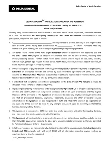
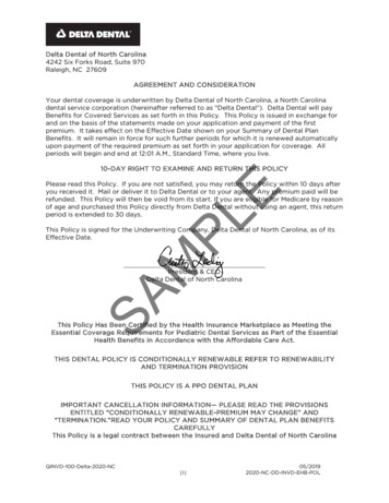
Wye-delta and Solid-state StartersFigure 5 - Sample Wye-Delta Connection DiagramStandard 6-LeadDual Voltage(Delta/Star Connected)(Low Volts/High Volts)DeltaT6StarT1T1T6T3T4T5T4T5T2T2T3Low VoltsHigh VoltsAs noted in Figure 4 (A) for connecting the motor for full voltage, leads 1 and 6 are connected together, forming T1 andare connected to L1. Correspondingly leads 3 -5 and 2 -4 are connected together, forming T3 and T2, respectively. Whenyou connect the motor for reduced voltage and starting current, you must connect the leads in the wye or starconfiguration. By connecting the motor in the star connection, leads 4, 5, and 6 are tied together and leads T1, T2, andT3 are connected to L1, L2, and L3. While these are common connections, always check with the motor manufacturer orthe user manual to confirm the connections are the same before you apply power.Electromechanical Wye-Delta vs. Solid-State StartersThe most widely used configuration of the electromechanical wye-delta starter is referred to as open transition. Thetypical circuit includes three separate contactors, an overload relay, a timer, and an interlock. A sample wiring diagram isincluded as Figure 9 on page 14.The term open transition is used to describe this method because the motor is momentarily disconnected from the linewhen changing from the wye to the delta configuration. This method has one important disadvantage. Depending on theloading of the motor and the timing of this transition, the resulting surge in current and torque could produce electricaland mechanical shocks on the system. In some cases the instantaneous current peaks can exceed even the locked rotorcurrent for short durations. Figure 6 (A) shows this effect graphically. Electrically the consequence of the instantaneouspeaks could be power fluctuations or losses. Mechanically the increased torque resulting from the current spike could beenough to damage system components (for example, snap a drive shaft).Figure 6 - Current and Speed Relationship for Various Reduced-voltage MethodsOpen Transition% FLC% FLC% Speed(A)6Closed TransitionSoft Starter% FLC% Speed(B)% Speed(C)Rockwell Automation Publication 150-AT005A-EN-P - July 2016
Wye-delta and Solid-state StartersAn alternate method to open transition wye-delta starting is called closed transition. The theory of operation is identicalwith the addition of a few components that are required to help eliminate or reduce the surge associated with the opentransition. The additional components include a contactor and few power resistors. The advantage of this method can beseen in Figure 6 (B) as the transition surge is virtually gone, while the disadvantage is that it needs additionalcomponents, panel space, and power consumption. A sample diagram of this circuit is provided as Figure 10 on page 14.The solid-state starters offer another technique of reduced-voltage starting. The use of solid-state electronics to controlthe voltage, and then provide transitionless starting has been employed throughout industry since the 1980s, as shown inFigure 6 (C). Solid-state starters, often referred to as soft starters, have primarily been used on three-lead, deltaconnected motors. However, you have always been able to apply these devices to six-lead motors. Wye-delta startersreduce the voltage to the motor through an electrical relationship and physical connection, while solid-state startersreduce the voltage electrically. By offering this connection option, all six motor leads are brought back to the control justlike they are with an electromechanical wye-delta starter. However, the motor is actually always connected in a deltaconfiguration, and that means the starting line current-to-torque ratio is different than that of a traditional wye-deltastarter.For a soft starter to replace a wye-delta starter, the soft starter must reduce torque or limit current during the wye or startmode and then switch to full voltage after a fixed time. You can meet these requirements by using the “current limit”mode of soft starting for a specified period of time. In addition, the electromechanical wye-delta starter has one fixedoutput (57.7% voltage), but the soft starter current limit mode allows several output levels that you can adjust to matchthe load requirement. The starting torque to current ratio for a soft starter that is wired to a six-lead motor varies as thesquare of the ratio of soft start starting current level (Icl) divided by the full-voltage starting current (ILRA). I cl 2Starting Torque Reduction x 100% I LRA Table 1 shows the torque output of a motor with a full-voltage starter, traditional wye-delta starter, and a soft starter atvarious current limit settings.Table 1 - Starting Torque and CurrentsStarting TypeFull VoltageWye-delta StartingSoft Start with various current limit settings150%200%250%300%350%400%450%% Voltage AppliedDuring Start% Full Load StartingTorque% Full Load 44956150200250300350400450Solid-State Starting AdvantagesThe latest extensions of the Rockwell Automation line of solid-state starters are the SMC-3, SMC Flex, and SMC-50.These products are designed to offer the basic functions of an electromechanical wye-delta starter, the reliability ofsolid-state starting, advanced motor protection, closed transition starting, and significantly smaller mounting panel spacethan both electromechanical and previous solid-state starters.Rockwell Automation Publication 150-AT005A-EN-P - July 20167
Wye-delta and Solid-state StartersOne perceived disadvantage is the fact that the current to torque ratio is less with a solid-state starter than with atraditional electromechanical starter. If we look again at Table 1, the soft start must be set up for 350% current limit toprovide the equivalent starting torque produced in the traditional wye-delta arrangement. The reason for this is themotor has a slightly different torque characteristic while connected in the wye for starting, as compared to beingconnected in the delta. The electromechanical starter connected in the wye configuration draws 1/3 the line currentwhich results in 33% of the starting torque. Referring to the example used earlier for a 15 kW/20 Hp motor, the wyeconnection current would be 60/51 A at 400/480V and 33% of the full load torque at starting. With the SMCcontroller, a 350% current limit is required to obtain the same torque output (34% FLT) from the motor, which resultsin current of 105/90 A at 400/480V.350% 2x 100% 34%T% 600% The electromechanical wye-delta starter actually provides more torque per line ampere than the solid-state starter;however, the torque is fixed at 33% of the normal starting torque. The adjustability of the SMC controller lets you moreclosely match the torque requirements of the system to the motor, providing better control and longer life of themechanical components.The solid-state soft starter is inherently a closed transition device and provides “transitionless” starting because the motorconnection is never removed. The advantages of this starting method include the reduction in components, spacerequirements, and the cost required to minimize the torque and current surges that occur when you switch from start torun mode.Some solid-state starters come standard with a built-in bypass contactor. This contactor maximizes power-handlingcapabilities of the product by using the silicon-controlled rectifiers (SCRs) to handle the currents that are required forstarting and using the bypass contacts to minimize power losses during running. Heating during running is the same aswith an electromechanical starter, so using this feature helps to minimize the enclosure size because it requires no extrapanel space.Another significant advantage of using a solid-state starter is the additional functionality and built-in diagnosticcapabilities. Protection features such as overload, underload, jam/stall, ground fault detection, phase loss, open load,phase unbalance and shorted SCR are just a few of the available features. The device can also protect itself from excessiveduty cycles or long starting times with internal over-temperature protection. Some products offer communicationscapabilities that allow them to share real-time status and telemetry information with various SCADA and informationsystems.The most influential driver is the cost associated with applying a starter to a motor. While breaking down the costs it isimportant to remember that the traditional wye-delta starter still requires a motor with a six-lead motor connection.Most European style motors have no additional costs for this feature, but NEMA style motors carry a cost adder of about20% on 180T frame (5 Hp) to 1% on a 449T frame (300 Hp). In comparison, a soft starter solution is 5 20% more thana standard full-voltage or wye-delta starter depending on the size. The cost differences become less as the motor sizeincreases; however, the functionality and features increase dramatically. A standard full-voltage starter offers zerofeatures, while a solid-state solution provides advanced motor control, maximum adjustability, diagnostics, and built-inprotective features.Though cost savings can be difficult to quantify, the installation alone can produce savings. A common thought is that itis more expensive to run six leads to a motor than three. While there is an additional cost to run more leads, the costsassociated with the installation are negligible when you compare them to the savings that you can achieve using thesmaller SMC controller in the inside-the-delta configuration.8Rockwell Automation Publication 150-AT005A-EN-P - July 2016
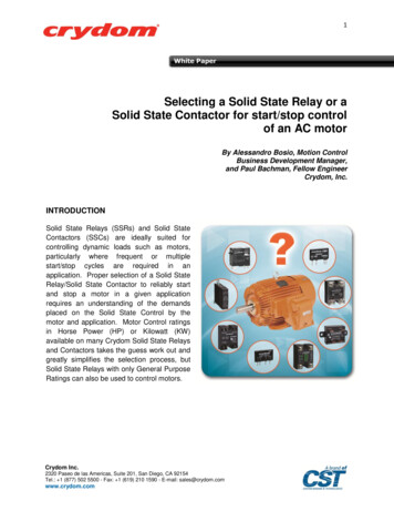
Wye-delta and Solid-state StartersWhile the advantages and enhanced features of the SMC product line are impressive, it is equally important to rememberthat it still has all of the traditional advantages of reduced-voltage starting, such as the mechanical torque and electricalreduction benefits. These alone can yield additional savings in terms of system maintenance and proactive detection ofproblems.Solid-State Starters for Wiring Inside-the-DeltaBy designing solid-state products such as the SMC-3, SMC Flex, and SMC-50 to be wired inside-the-delta, increased Hp(kW) capacity can be achieved through the standard product offering. Remember that the actual current handlingcapacity of the device and physical connection does not change, but is due to the physical and electrical relationships of asix-lead motor.SizingFigure 7 depicts the differences between inside-the-delta and outside the delta wiring. In Figure 7(B) each SCR andbypass is exposed to a portion of the total current draw of both motor windings attached at each corner of the delta. Theinside-the-delta wiring shown as Figure 7 (A) shows how each SCR and bypass contactor is only subjected to the currentof one winding. This value, as explained earlier, is equal to the full load current divided by 1.73.Figure 7 - Inside-the-Delta vs. DeltaL1L2L3L1L2L3T2T4T2T1T5T3T6T1T3(A)(B)SMC wired Inside-the-Deltawith 6-lead Wye-Delta motorSMC wired to 3-lead Delta motorAs an example, the 480 A SMC Flex is capable of handling a motor connected wye-delta with a FLA of up to 831 A(480 x 1.73). This increase in current-carrying capacity translates directly into an increase in Hp. Table 2 shows themaximum Hp and kW supported for several SMC controller current ranges based on the connection configuration.Rockwell Automation Publication 150-AT005A-EN-P - July 20169
Wye-delta and Solid-state StartersTable 2 - Horsepower Capacity of Soft StartersCurrent CapacityMax Hp @ 460V ACMax. kW @ 380V 132160250315355450ConnectionSMC FlexMost increases in power capacity occur at the higher current range offering of each product. This is primarily due to theintegration of the overload into the product. The overload current adjustment for a particular product must match thenominal FLA currents of the supported Hp (kW) range. Whether the application is being retrofitted or new, it isimportant to follow the selection tables for open delta connected controllers.Connections and SetupWiring of the SMC-3 and SMC Flex is simple due to several product enhancements that aid the connection process. Youcan wire connections almost the same as a conventional wye-delta starter. Figure 8 provides simple power wiringdiagrams for both six-lead and 12-lead motors. There is a slight difference between the wiring of the two devices, with theSMC Flex having an internal connection to the line side located on the load side. The leads T4 - T6 and T10 - T12 of theSMC-3 and SMC-50 controllers are connected on the line side of the controller. Additional wiring diagrams with samplecontrol wiring begin on page 14.10Rockwell Automation Publication 150-AT005A-EN-P - July 2016
Wye-delta and Solid-state StartersFigure 8 - Sample Power Wiring 3 and SMC-50 with 6-lead motorL1L2L3T12T10T11T1T2T3L1T12T5, T8T4, T7SMC Flex with 6-lead motorT1L2T10L3T2T11T3T5, T8T4, T7MMT6, T9SMC-3 and SMC-50 with 12-lead motorT6, T9SMC Flex with 12-lead motorConnecting the three incoming power lines, the six or 12 motor leads, and as few as two control wires for two-wirecontrol or three control wires for three-wire control can complete the wiring. Enhancements such as locating the powerterminals conveniently on the unit and the elimination of costly inter-wiring helps to reduce panel space requirementsand provides saving significant time in wiring.Since these starters are designed to replace standard wye-delta starters once the connections have been made, simpleoperation can be accomplished by setting the following starting mode characteristics. Start Mode — Current Limit (For typical wye-delta application this may be 350%) Start Time — Desired Start Time (Consult the factory for extended start time capabilities) Overload — Desired Overload class (Class 10 common for IEC motors, Class 20 for NEMA) FLA Setting — Set the motor’s full load current (Found on motor nameplate)Rockwell Automation Publication 150-AT005A-EN-P - July 201611
Wye-delta and Solid-state StartersWith these minimal settings and connections, the product can provide all the functions required to replace a traditionalwye-delta starter, as well as provide all the proper motor protection. Additional functionality and advanced features canbe configured by referencing the specific product user manual, but are not required for the basic setup.Application ExamplesSince the SMC-50 soft starter was designed to be used in the same type of applications as electromechanical wye-deltastarters, let’s review the ideal reduced-voltage starting applications.Controlling the motor torque is a prime application consideration when you apply solid-state starters. When motortorque exceeds the system requirements, it can cause extreme wear and reduced life of mechanical components. Failure ofcomponents, such as couplings, gears, chains, sprockets, and belts, leads to unscheduled shut downs and lost production.The SMC-50 soft starter provides fully adjustable starting current levels from 50 to 600%. Applications that requirecontrolling the starting torque are in many industries, including material handling; heating, ventilation, and airconditioning (HVAC); mining; and wastewater treatment, where the main applications are fans, pumps, conveyors, andcompressors.The HVAC industry is a prime environment for the application of solid-state starters due to the history of using the wyedelta motor starting method. Air handling and centrifugal loads make up the majority of system components and mostconsist of large Hp motors. A solid-state starter serves as an ideal replacement for legacy applications while offeringcontractors and original equipment manufacturers savings in terms of wiring and installation time and space.Every industry has applications where the advantages of solid-state starters can be realized. Even simple fan applicationshave low starting torque requirements. Fans can be either directly connected to the motor or belted. The fans that arebelted usually require torque control during starting to help eliminate or reduce excessive belt wear as a result of slippageduring across the line starting. Pumps also have low starting torque profiles. The initial torque and acceleration torquecan be critical in some pumping applications and is usually determined by the design of the pump. Some pumps, such asthose with long shafts connecting the motor to the pump, may be damaged if the starting toque is too high. The need tocontrol the acceleration torque is evident where shock and vibration are created in the pumping system when the pumpstarts at full voltage. In some cases, the Pump Control or Linear Acceleration option in the SMC-50 controller helps tosignificantly reduce the “water hammering” effect found in large systems.Like fans and pumps, some types of compressors need low torque to accelerate to full speed. Reciprocation compressorsrequire high starting torque especially when starting under load. Other types such as centrifugal and axial vane typerequire low starting torque because of the design characteristics. These are typically started unloaded and are perfectcandidates for reduced-voltage starting.For other types of applications, reduced-voltage starting may be necessary to limit inrush currents instead of controllingtorque. The need to limit the inrush current may be due to government mandates, power company restrictions ordistribution system limitations. Operation in areas that are adjacent to or within a residential area may need to limitcurrent during starting to help eliminate voltage drops that cause light flicker. A good example of this is on pumps forhydraulic elevators in an apartment complex. These pumps have low starting torque requirements, so limiting currentduring starting minimizes any line sags that would have occurred if the pump was started direct on line.In instances where limiting the current is more critical than torque, the electromechanical wye-delta starter has only onesetting — 200% current limit. The SMC-50 controller is fully adjustable. With this adjustment, it is possible to select alevel that meets the specific needs of each application while still allowing sufficient torque available at the reduced level toaccelerate the load.12Rockwell Automation Publication 150-AT005A-EN-P - July 2016
Wye-delta and Solid-state StartersImportant Application ConsiderationsThe latest SMC products have built-in overload protection, and most products also have an integral bypass contactor.Select them according to the motor to which they are being applied. Because the bypass is built in, the increased thermalcapacity requirement of some applications does not require the SMC controller to be oversized. One exception is due tothe decreased efficiency of fans and heat sinks, it may be necessary to de-rate the SMC products for applications above6,500 feet (2000 m). In most cases, choosing the next size product provides enough thermal capacity to guard against thepotential of over-temperature trips. However, it is important to make sure that the motor full load current (FLA) stillfalls into the devices acceptable FLA adjustment range.Soft starters can be successfully applied on a wide range of applications which require the controlling (limiting) of torqueor the reduction of inrush current. A common and more costly alternative to a soft starter is a Variable Frequency Drive(VFD), which differs in both the theory of operation and functionality. Drives can completely manage the motor torqueat any speed. Soft starters only provide control in the form of reduced torque and reduced current during starting. Asidentified earlier, applications that have low initial torque demands are ideal for using these products.The time it takes the motor to accelerate the load to full speed is crucial. When the transition from start to run takesplace before the motor is up to speed, there is a surge in current much like an open transition. Since the SMC controllersare closed transition, they do not switch to the bypass contactor until the current has fallen below 120% of the motorsfull load current. If the programmed start time has elapsed and the motor has not reached rated speed, the devicecontinues to run with
The latest generation of soft starters and Smart Motor Controllers (SMCs) offers significant advantages over its predecessors when it comes to using it in wye-delta applications. In most cases, you can use these solid-state products to . single-voltage wye-delta motor and a 12-lead, dual-voltage wye-delta motor. Figure 4 - Sample Motor .