Transcription
Enclosure cooling unitSK 3186930SK 3187930SK 3188940SK 3189940Assembly and operating instructions
ENPrefaceENPrefaceDear Customer!Thank you for choosing a "Blue e " enclosure coolingunit (referred to hereafter as "cooling unit") from Rittal.YoursRittal GmbH & Co. KGRittal GmbH & Co. KGAuf dem Stützelberg35745 HerbornGermanyPhone: 49(0)2772 505-0Fax: 49(0)2772 505-2319E-mail: info@rittal.comwww.rittal.comwww.rittal.deWe are always happy to answer any technical questionsregarding our entire range of products.2Rittal enclosure cooling unit
ContentsContents1Notes on documentation . 41.11.21.31.4CE labelling.Storing the documents.Symbols used in these operating instructionsOther applicable documents .2Safety notes . 52.12.22.3General safety instructions . 5Operating and technical staff. 5Other dangers when using the cooling unit . 53Product description . 63.1Functional description and components. 63.1.13.1.23.1.33.1.43.1.53.1.63.1.7Function .Components .Control .Safety devices .Condensation .Filter mats .Door limit switch .3.23.3Proper use, foreseeable misuse . 8Supply includes. 84Transport and handling . 94.14.24.3Delivery . 9Unpacking . 9Transport . 95Installation . 105.15.25.3Safety instructions. 10Siting location requirements . 10Assembly procedure . 105.3.15.3.25.3.35.3.45.3.5Assembly instructions .Mounting options .Make a mounting cut-out in the enclosure .External mounting of the cooling unit .Mounting the cooling unit externally on a 500 mmdeep enclosure .5.3.6 Partial internal mounting of the cooling unit .5.3.7 Full internal mounting of the cooling unit .5.3.8 Connect the condensate water discharge .444467777787.4Configuration menu. 267.4.17.4.27.4.37.4.4Temperature .Alarm relays .Language settings .Self-test .7.5System messages. 28EN262727277.5.1 Occurrence of a malfunction . 287.5.2 Display in case of errors . 287.6List of system messages . 298Inspection and maintenance . 328.18.28.38.4Safety instructions for maintenance work .Notes on the refrigerant circuit .Maintenance work on the cooling unit .Compressed air cleaning.323232328.4.18.4.28.4.38.4.4Dismantling a unit with full internal mounting .Dismantling the unit .Cleaning the components with compressed air .Re-assembling the cooling unit .323235359Storage and disposal . 3610Technical specifications . 3711List of spare parts . 3912Drawings . 4012.1 Representation of mounting cut-outs . 4012.2 Dimensions and installation depths . 4113Accessories . 4314Customer service addresses . 4415Compact service information . 4810111212141418195.4Electrical connection . 205.4.15.4.25.4.35.4.4Notes on electrical installation .Install the power supply .Connect the alarm relays .Interfaces .6Commissioning . 237Operation . 247.17.2General . 24Layout of the display . 24202122227.2.1 Start screen . 247.2.2 Changing a parameter value . 247.3Information menu . 257.3.1 Temperature information . 257.3.2 Device information . 257.3.3 Efficiency information . 26Rittal enclosure cooling unit3
1 Notes on documentationEN1Notes on documentation1.1CE labellingRittal GmbH & Co. KG confirms the conformity of thecooling unit with the European Union's Machinery Directive 2006/42/EC and EMC Directive 2004/108/EC.A corresponding declaration of conformity has been issued and enclosed with the unit.1.2Storing the documentsThe assembly and operating instructions as well as allother applicable documents are an integral part of theproduct. They must be issued to everyone who workswith the unit and must always be available and on handfor operating and maintenance personnel.1.3Symbols used in these operating instructionsThe following symbols are used in this documentation:Danger!A dangerous situation in which failure tocomply with the instructions will result indeath or severe injury.Warning!A dangerous situation which may causedeath or serious injury if the instructionsare not followed.Caution!A dangerous situation which may lead to(minor) injuries if the instructions are notfollowed.Note:Important notices and indication of situationswhich may result in material damage. This symbol indicates an "action point" and shows thatyou should perform an operation or procedure.1.4Other applicable documentsAssembly and operating instructions exist as paper documents and/or digital data carriers for the unit types described here and are enclosed with the equipment.We cannot accept any liability for damage associatedwith failure to observe these instructions. Where applicable, the instructions for any accessories used also apply.4Rittal enclosure cooling unit
2 Safety notes2Safety notes Where applicable, use suitable components to divertGeneral safety instructions Please observe the prescribed minimum distances atENthe air.2.1Please observe the following general safety instructionsfor the installation and operation of the system:– Please be sure to observe the applicable regulationsgoverning electrical installations of the country inwhich the device is installed and operated as well asnational regulations for accident prevention. Pleasealso observe any internal company regulations, suchas work, operating and safety regulations.– Use only original Rittal products or products recommended by Rittal in conjunction with the cooling unit.– Please do not make any changes to the cooling unitthat are not described in these operating instructionsor other applicable assembly and operating instructions.– The operational safety of the cooling unit is only warranted if used as intended. The technical specifications and limit values stated must not be exceeded under any circumstances. In particular, this applies to thespecified ambient temperature range and IP protection category.– Operating the cooling unit in direct contact with water,aggressive materials or inflammable gases and vapours is prohibited.– Other than these general safety instructions, it is alsovital to observe the specific safety instructions whencarrying out the tasks described in the following chapters.– Please note the maximum weights that may be liftedby individuals. It may be necessary to use lifting gear.2.2the installation site as outlined in section 5.3.1 "Assembly instructions".Operating and technical staff– The assembly, installation, commissioning, maintenance and repair of this cooling unit may only be performed by qualified, trained personnel.– Only properly instructed personnel may operate acooling unit with the system operational.– Children and persons with limited cognitive/coordinative abilities must not operate, maintain or clean theunit or be allowed to use it as a toy.2.3Other dangers when using the coolingunitParticularly when the cooling unit is externally mounted(see section 5 "Installation"), there is a risk that the enclosure could become unbalanced and tip over. In such cases, the enclosure should be bolted to thefloor as a precaution.If the air inlet or outlet of the cooling unit is obstructed,there is a risk of air short-circuits, resulting in inadequateclimate control. Please ensure that the electronic assemblies in the enclosure are installed in accordance with section 5.3.1"Assembly instructions".Rittal enclosure cooling unit5
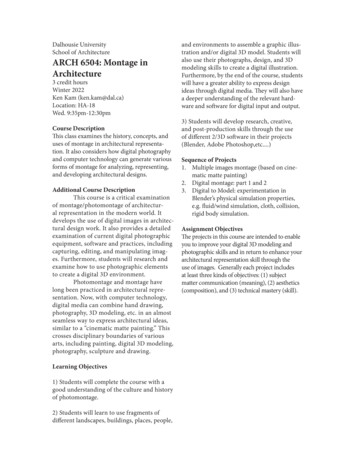
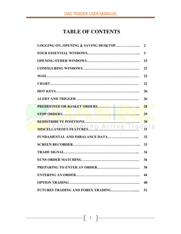
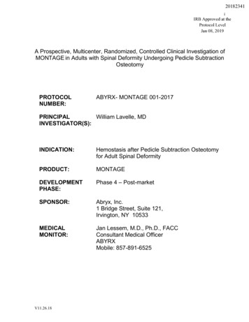
3 Product descriptionEN3Product description3.1Functional description and components3.1.1 FunctionThere are two separate cooling circuits installed in thecooling unit.– One conventional refrigerant circuit (compression system), and– One heat pipe integrated into the condenser andevaporator coil.Fig. 1:Key123456789101112Cooling circuitCompressorCondenser (dual version) with fanExpansion valveEvaporator coil (dual version) with fanRefrigerant circuit with heat pipeRefrigerant circuit with compression systemInternal circuitExternal circuitDryer/collectorInternal fanExternal fanPSAH pressure monitorRefrigerant circuit with compression systemThe refrigerant circuit with compression system is comprised of the following four main components:1. Evaporator coil2. Compressor3. Condenser4. Expansion valveThe evaporator coil fan draws hot air from the enclosurein the internal circuit of the cooling unit and passes itover the evaporator coil. After the evaporator coil, thecooled air is fed back into the enclosure via the outletopening.The air is cooled down by evaporating the refrigerant inthe evaporator coil. The refrigerant vapour is transportedby the compressor in the external circuit of the coolingunit to the condenser. There, the refrigerant condensesand becomes a liquid. The heat produced is dissipatedby the condenser fan. The downstream electronic expansion valve reduces the high pressure of the refrigerant, and the refrigerant is then fed back into the evaporator coil.Both the compressor and the two fans in the cooling unitare activated via an inverter. This makes it possible tocontrol these components, so that the fan and compressor may be activated for a longer time but at a lower output and improved efficiency.Refrigerant circuit with heat pipeThe additional second refrigerant circuit operates without a compressor, expansion valve or other control elements, and is integrated into the evaporator coil andcondenser as a heat pipe.The refrigerant inside the heat pipe (R134a) absorbsthermal energy from the intake of enclosure air andevaporates. The gaseous refrigerant then rises throughthe pipeline until it reaches the condenser. The refrigerant is cooled down again in the condenser (provided Tu Ti), and the heat released is emitted into the environment. Gravity then causes the liquid refrigerant to flowback down the pipelines. The whole cycle begins again.In both cooling circuits, the individual components areconnected with pipes in which the refrigerant R134a iscirculating. This refrigerant is very environmentally friendly, thanks to the following properties:– Chlorine-free– Does not deplete the ozone layer (ozone destructionpotential ODP 0)6Rittal enclosure cooling unit
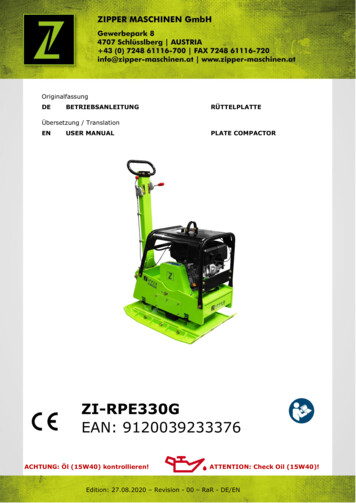
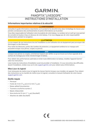
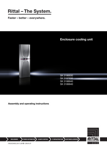
3 Product description3.1.2Fig. 2:Key1234567891011ComponentsMain components of cooling unitCoverChassisConnection boxEvaporator fanHandleAir outlet openingLower louvred grille for air inletDisplayInfill panelUpper louvred grille for air outletThread for eyebolt3.1.3 ControlRittal enclosure cooling units are fitted with a controllerfor setting the functions of the cooling unit.Operation using this controller is described in section 7"Operation".3.1.4 Safety devices– In the refrigerant circuit, the cooling units have a typetested pressure monitor (to EN 12263) which switchesoff the cooling unit if the maximum admissible pressure is exceeded. Once the pressure drops back below the admissible pressure, the unit will automaticallyresume operation.– Temperature monitoring prevents the evaporator coilfrom icing over. If there is a risk of icing, the compressor switches itself off and automatically switches itselfback on again at higher temperatures.– The compressor is monitored and protected by the inverter to prevent overloading.– The fans have a built-in overload protection with automatic reset.Rittal enclosure cooling unit– In order to allow a reduction of pressure inside thecompressor and hence a safe restart, once it has beenswitched off (e.g. upon reaching the set temperaturevia the door limit switch function or via de-energising),the device will switch back on with a delay of 180 seconds.– The device has floating contacts on the connectionpins on terminals 1 and 3 of the signal connector (X2),via which system messages from the device may bepolled, e.g. using a PLC (2 x normally closed or normally open contacts).3.1.5 CondensationAt high levels of humidity and low temperatures insidethe enclosure, condensate water may form on the evaporator coil.The cooling units have an automatic electrical condensate water evaporator. The thermal component used forthis purpose is based on self-regulating PTC technology. Condensate water arising on the evaporator coil iscollected in a tank in the external circuit of the coolingunit, and partially evaporated via the airflow. When thewater level rises, the water enters the PTC thermal component and is evaporated (through-flow heater principle). The water vapour streams out of the cooling unitwith the airflow from the external fan.The PTC thermal component is activated automaticallywhen the compressor is running, and continues to runfor around 15 minutes after the compressor has beenswitched off. During the after-run phase, the condenserfan will likewise continue to run at low speed.In the event of a short-circuit in the PTC component or ifthere is a risk of inverter overload (possible at high ambient temperatures), the PTC component will be deactivated. This means that any condensate water arisingcan be discharged via the safety overflow.If the fuse has tripped, any condensate water is drainedoff via the safety overflow. The condensation is routeddownwards out of the unit via a drain pipe on the evaporator coil divider panel. For this purpose, a hose may beconnected to the condensate water nozzle (see section5.3.8 "Connect the condensate water discharge").3.1.6 Filter matsThe entire cooling unit condenser is covered with a dirtrepelling, easy-to-clean RiNano coating. In many applications, therefore, the use of filter media is unnecessary,particularly with dry dusts.For dry, coarse dust and lint in the ambient air, we recommend installing an additional PU foam filter mat (available as an accessory) in the cooling unit. Depending onthe incidence of dust, you will need to replace the filtermat from time to time (see section 8 "Inspection andmaintenance").For oily ambient air, we recommend the use of metal filters (also available as an accessory). These may becleaned with suitable detergents and reused.7EN
3 Product descriptionEN3.1.7 Door limit switchThe cooling unit may be operated with a floating doorlimit switch connected. The door limit switch is availableas accessory from Rittal.The door limit switch function causes the fans and thecompressor in the cooling unit to gradually slow downand then switch off after approximately 15 secondswhen the enclosure door is opened (contacts 1 and 2closed). This prevents the formation of condensate water inside the enclosure while the enclosure door isopen. In order to prevent damage to the unit, it isequipped with an ON delay: The evaporator fan will cutin again after a delay of a few seconds on closure of thedoor.Please note that no external voltage may be applied tothe door contacts (terminals 1 and 2)3.3Supply includesQty.Description1Enclosure cooling unit1Shipping bag with1– Declaration of conformity1– Assembly and installation instructions1– Assembly, installation and operating instructions on digital data carrier1– Warning and safety notes6– Grub screws M8 x 40 mm6– Nut-and-washer assembly M81– Sealing tape 10 x 10 mm, L 4.1 m1– Signal connector X21– Connector X11– Cover for connection unit1– Membrane entry grommet1– Clip1– Wedge element6– Fixing clamps4– Corner bracket for internal/externalmounting2– L-shaped bracketsConsequently, the cooling unit must only be used properly and in a technically sound condition! Any malfunctions which impair safety should be rectified immediately.1– Earth clamp 4 NS1– Earth clamp 5 NS1– Washer for attaching the earth clampProper use also includes the observance of the documentation provided, and compliance with the inspectionand maintenance conditions.1– Contact washer for attaching the earthclamp1– M4 nut for attaching the earth clamp1– Cable gland M20 x 1.5 mm1– EMC cable gland M20 x 1.5 mm1– Strain relief3.2Proper use, foreseeable misuseThe cooling unit is only intended for cooling connectedenclosures. Any other use is not permitted.– The unit must not be installed and operated in locations which are accessible to the general public (seeDIN EN 60335-2-40, paragraph 3.119).– The unit is designed solely for stationary use.– The manufacturer's consent must be obtained in advance for mobile applications, e.g. on cranes.The cooling unit is state of the art and built according torecognised safety regulations. Nevertheless, improperuse can pose a threat to the life and limb of the user orthird parties, or result in possible damage to the systemand other property.Rittal GmbH & Co. KG is not liable for any damage whichmay result from failure to comply with the documentation provided. The same applies to failure to comply withthe valid documentation for any accessories used.Inappropriate use may be dangerous. Examples of inappropriate include:– Use of the cooling unit over long periods with the enclosure open.– Use of impermissible tools.– Improper operation.– Improper rectification of malfunctions.– Use of accessories not approved by Rittal GmbH &Co. KG.8Tab. 1: Supply includesRittal enclosure cooling unit
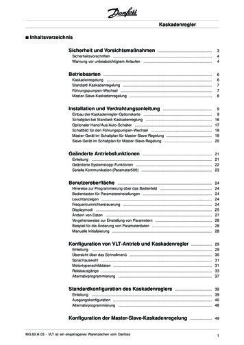
4 Transport and handling4Transport and handling4.1DeliveryENThe cooling unit is supplied in one packaging unit. Check the packaging carefully for signs of damage.Traces of oil on damaged packaging indicate a loss ofrefrigerant and/or a leak in the cooling unit. Any packaging damage may be the cause of a subsequentfunctional failure.Fig. 3:4.2Unpacking Remove the packaging materials from the cooling unit.Note:After unpacking, the packaging materialsmust be disposed of in an environmentallyfriendly way. Check the cooling unit for any damage that may haveoccurred during transport.Note:Damage and other faults, e.g. incomplete delivery, should be reported immediately, inwriting, to the shipping company and to RittalGmbH & Co. KG.Thread and eyebolt on top of the chassisKey1Eyebolt2M12 thread Before transporting by crane, please ensure that thelifting gear and crane have sufficient load capacity totransport the cooling unit safely. Never allow anyone to stand beneath a suspendedload, even for a short time, during transportation bycrane. Protect the lifting gear on the crane hook from load deflection, because the load's centre of gravity may beoff-centre. First position the cooling unit close to the installationsite and protect from accidentally being knocked over. Check the supply contents for completeness (see sec-tion 3.3 "Supply includes").4.3TransportDepending on the chosen version, the cooling unit mayweigh up to 85 kg. The components in the cooling unitchassis account for the bulk of the weight.Warning!Please note the maximum weights thatmay be lifted by individuals. It may benecessary to use lifting gear.At the rear of the cooling unit is a handle which can beused to briefly lift the cooling unit when inserting into themounting cut-out.There is also an M12 thread at the top of the chassis,into which a Rittal eyebolt (e.g. belonging to an enclosure) may be screw-fastened. The cooling unit is readilytransported with the aid of lifting gear and an indoorcrane.Note:An eyebolt with M12 thread may be orderedas an accessory from Rittal (see section 13"Accessories").Rittal enclosure cooling unit9
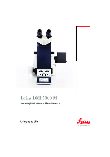
5 InstallationEN5Installation5.1Safety instructionsWarning!Please note the maximum weights thatmay be lifted by individuals. It may benecessary to use lifting gear.Warning!Work on electrical systems or equipment may only be carried out by an electrician or by trained personnel under theguidance and supervision of an electrician. All work must be carried out in accordance with electrical engineeringregulations.The cooling unit may only be connectedafter the aforementioned personnel haveread this information!Use only insulated tools.Follow the connection regulations of theappropriate electrical supply company.The cooling unit must be connected tothe mains via an all-pin isolating deviceto overvoltage category III (IEC 61058).The cooling unit is not de-energised untilall of the voltage sources have been disconnected!– The installation site must be free from excessive dirt,aggressive ambient conditions and moisture.– The ambient temperature must not exceed 60 C.– It must be possible to fit a condensate water discharge(see section 5.3.8 "Connect the condensate waterdischarge").– The mains connection data as stated on the ratingplate of the cooling unit must be guaranteed.Size of installation room– Units SK 3186930 and SK 3187930 must not be installed in rooms of less than 6 m³.– Units SK 3188940 and SK 3189940 must not be installed in rooms of less than 12 m³.Electromagnetic interference (EMI)– Interfering electrical installations (high frequency) mustbe avoided.5.3Assembly procedure5.3.1 Assembly instructions Before assembling, please ensure that the enclosureis sealed on all sides (IP 54). Increased condensationwill occur later during operation if the enclosure is notairtight. If applicable, additionally fit a door limit switch (such as4127.010) to the enclosure which switches off thecooling unit when the enclosure door is opened to prevent excessive condensation (see section 3.1.7 "Doorlimit switch"). Please ensure that the electronic assemblies in the enclosure allow the even circulation of air. Please be sure to observe the applicable regulationsgoverning electrical installations of the country inwhich the device is installed and operated, as well asnational regulations for accident prevention. Pleasealso observe any internal company regulations, suchas work, operating and safety regulations. The technical specifications and limit values statedmust not be exceeded under any circumstances. Inparticular, this applies to the specified ambient temperature range and IP protection category.5.2Siting location requirementsWhen choosing the installation site for the enclosure,please observe the following:– The site for the enclosure, and hence the positioningof the cooling unit, must be carefully selected so as toensure good ventilation (clearance between coolingunits and clearance between a cooling unit and thewall must be at least 200 mm in each case).– The cooling unit must be installed and operated with amaximum deviation of 2 from the vertical.10Fig. 4:Never direct the cold airflow at active componentsRittal enclosure cooling unit
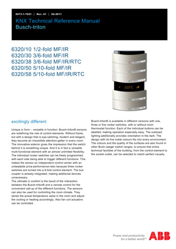
5 Installation Under no circumstances should the air inlet and outletENopenings of the cooling unit be obstructed. Only in thisway is it possible to ensure that the maximum coolingoutput is available. Please ensure that the cold airflow from the coolingunit is not directed at active components.Fig. 6:Mounting optionsKey1External mounting2Partial internal mounting3Full internal mountingFig. 5:Never direct the cold airflow at active components If appropriate, install components to divert the air. When installing in a dismantled door or side panel,please ensure that it cannot fall over when installingthe cooling unit in the mounting cut-out.Note:The pictures in this chapter illustrate the installation of the cooling unit in an enclosuredoor. Installation in a side panel is carried outin the same way.5.3.2 Mounting optionsIn principle, there are three different options for installingthe cooling unit on an enclosure door or side panel.– External mounting: All of the cooling unit is outside theenclosure.– Partial internal mounting The cooling unit chassis is inside the enclosure, while the cover and the louvredgrilles are outside.– Full internal mounting: All of the cooling unit is insidethe enclosure. Only the louvred grilles project on theoutside.Note:– Full installation of the 6 kW cooling unit isnot possible.– On an enclosure with 500 mm depth, theunit may only be externally mounted on theside panel.Your chosen installation option will ultimately depend onhow much space you require inside and outside of theenclosure. The various mounting options have no influence on the cooling output of the cooling unit, which remains the same in all cases.– If there are a large number of components installed inside the enclosure, external mounting or partial internal mounting of the cooling unit may be appropriate. In such cases, the space inside the enclosure maybe insufficient for full internal mounting, or it may notbe possible to guarantee adequate cooling of all components inside the enclosure.– If the space surrounding the enclosure is limited,full internal mounting may be suitable, so as to keepessential escape routes clear.Rittal enclosure cooling unit11
5 InstallationEN5.3.3 Make a mounting cut-out in the enclosureIn order to mount the cooling unit on the enclosure, asuitable mounting cut-out must be made in the door orside panel of the enclosure. In principle, the mountingcut-out is identical for all three mounting options. A special mounting cut-out is only required for external mounting on the side panel of a 500 mm deep enclosure.Note:The dimensions of the mounting cut-outscan be found in section 12.1 "Representationof mounting cut-outs". Using the diagrams in section 12.1 "Representation ofmounting cut-outs", calculate the required dimensionsfor your mounting cut-out . Drill all the required holes and make the mounting cutout. Carefully deburr all drilled holes and the cut-out to prevent injuries caused by sharp edges.Caution!Drilled holes and cut-outs that have notbeen fully deburred may cause cut injuries, particularly when assembling thecooling unit.5.3.4External mounting of the cooling unitNote:The description in this section does not apply to external mounting of the cooling unit onthe side panel of a 500 mm deep enclosure.This is described in section 5.3.5 "Mountingthe cooling unit externally on a 500 mm deepenclosure".Fig. 7:Key1234Threaded bolts at the rear of the cooling unitRear of cooling unitLower threaded boltJoint of sealing tapeCover Push the clip included with the supply into the relevanthole at the top edge of the cooling unit at the rear.This clip will prevent the cooling unit from falling out ofthe mounting cut-out later on if it is not yet adequatelysecured with the threaded bolt. Cut the sealing tape in the dispatch bag to the re-quired length so that it can be placed all the way roundthe rear of the cooling unit once. Start by positioning the sealing tape on the bottomedge, so that the joint between the two ends of thesealing tape is likewise on the lower edge of the unit. Carefully stick the sealing tape as close to the edge aspossible on the rear of the cooling unit. Screw the four threaded bolts into the blind nuts in thecorners at the rear of the cooling unit.Fig. 8:Clip at the rear of the cooling unitKey1Clip2Rear of cooling unit12Rittal enclosure cooling unit
5 Installation Lift up the cooling unit, preferably from a lifting eye us-ENing suitable lifting gear, and initially set the cooling unitdown with the two bottom threaded bolts on the dooror side panel of the enclosure. If transportation by crane is not possible, lift the cooling unit into the mounting cut-out in the same way using the handle.Fig. 11:Corner brackets on the threaded boltsKey1Corner bracket2Threaded boltFig. 9:Threaded bolt in door cut-outKey1Inside of enclosure door2Threaded bolts at bottom (2x)3Cooling unit on the outside of the enclosure door Next, attach the two corner brackets to the threadedbolts at the bottom and secure with the correspondingnuts. Slide the cooling unit into the mounting cut-out at thetop until the clip behind the cut-out latches home.Fig. 10:Clip in mounting cut-outKey1Inside of enclosure door2Clip Attach the two corner brackets to the threaded boltsat the top and secure with the corresponding nuts.Fig. 12:Key1234Threaded bolts at rearThreaded bolts (4x)Fastening clamps (6x)Rear of cooling unitCooling unit in front of enclosure door Insert the six fastening clamps into the
2 Rittal enclosure cooling unit Preface Dear Customer! Thank you for choosing a "Blue e " enclosure cooling unit (referred to hereafter as "cooling unit") from Rittal. Yours Rittal GmbH & Co. KG Rittal GmbH & Co. KG Auf dem Stützelberg 35745 Herborn Germany Phone: 49(0)2772 505-0 Fax: 49(0)2772 505-2319 E-mail: info@rittal.com www.rittal.com .