Transcription
INSTALLATION AND OPERATION INSTRUCTIONSOWNER / INSTALLER: For your safety this manual must be carefully and thoroughly read andunderstood before installing, operating or servicing this heater.SUNSTAR ECLIPSEINFRARED RADIANT TUBE HEATERSingle Stage Pull Through System (Negative Pressure)Models: SIR25, SIR35, SIR45 – (N5/L5)!INSTALLER: This manual is the property of the owner. Please present this manual to theowner when you leave the job site. WARNING: Improper installation, adjustment, alteration, service, or maintenance cancause property damage, injury or death. Read the installation, operation and maintenanceinstructions thoroughly before installing or servicing this equipment.IF YOU SMELL GAS:FOR YOUR SAFETY! DO NOT try to light any appliance.! DO NOT touch any electrical switch; DO NOT use anytelephone in your building.! IMMEDIATELY call your gas supplier from a neighbor'stelephone. Follow the gas supplier's instructions. If youcannot reach your gas supplier, call the fire department.DO NOT store or use gasoline or otherflammable vapors and liquids in the vicinity ofthis or any other appliance.!IMPORTANT: SAVE THIS MANUAL FOR FUTURE REFERENCE.SUNSTAR HEATING PRODUCTS, INC.Post Office Box 36271 (28236) 306 West Tremont Avenue (28203) Charlotte, North CarolinaPhone (704) 372-3486 Fax (704) 332-5843 www.sunstarheaters.com email: info@sunstarheaters.comForm 43471010Sept 2011
TABLE OF 23.0)DESCRIPTIONPAGESafety . 2Installer Responsibility . 2General Information. 2Minimum Clearances to Combustibles. 4Specifications. 5Packing List . 5Accessory Packages . 6Dimensions – SIR Series. 7Heater Assembly Overview . 8Typical Suspension Methods . 9Heater Assembly .10Gas Connections and Regulations.13Instructions for Pressure Test Gauge Connection .15Electrical Connections .16Venting .19Air for Combustion .24Direct Outside Air for Combustion .24Lighting and Shutdown Instructions.26Sequence of Operation.26Control Component Location.27Cleaning and Annual Maintenance .28Troubleshooting Guide.29Replacing Parts .32Removal of Spark Electrode .32Removing Main Burner and Gas Valve .33Air Switch Pressure Check .33Ignition System Checks .34Motor and Blower Wheel Check.35Installation Data .35Replacement Parts Guide .36This heater complies with ANSI Z83.20 (current standard) and CSA 2.34. Copies of the National Fuel Gas Code (ANSIZ223.1-latest edition) are available from the CSA at 8501 East Pleasant Valley Road, Cleveland, Ohio 44131 or 55 ScarsdaleRoad, Don Mills, Ontario M3B 2R3. All NFPA codes are available from the National Fire Protection Association, BatterymarchPark, Quincy, Massachusetts 02269.For installations with mounting heights less than 10 feet, install theheater at the highest possible height for the best radiant energydistribution.Form 43471010Sept 2011-1-
1.0)SAFETYThis heater is a self-contained infrared radiant tube heater. Safety information required during installation andoperation of this heater is provided in this manual and the labels on the product. The installation, service andmaintenance of this heater must be performed by a contractor qualified in the installation and service of gasfired heating equipment.All personnel in contact with the heater must read and understand all safety information, instructions and labelsbefore operation. The following symbols will be used in this manual to indicate important safety information.SAFETY REQUIREMENTSREQUIREMENTS The heater area must be kept clear and free from combustible materials, gasoline and other flammablevapors and liquids. This heater is designed for use with one type of gas (LPG or Natural). Make sure that the type of gas to besupplied to this heater matches that shown on the heater rating plate. DO NOT install this heater directly onto an LPG container or propane cylinder without directions from yourpropane company. LPG containers (propane cylinders) must not be stored indoors or in the vicinity of anygas-burning appliance. Children and adults should be alerted to the hazards of high surface temperatures and should stay away toavoid burns or clothing ignition. Clothing or other flammable materials should not be hung from the heater or placed on or near the heater. Young children should be carefully supervised when they are in the same space as the heater. NEVER attempt to service the heater while it is plugged in, operating or hot. Any guard or other protectivedevice removed for servicing a heater must be replaced prior to operating the heater.Warning instructions must be followed to prevent or avoid hazards whichmay cause serious injury, property damage or death.Caution instructions must be followed to prevent incorrect operation orinstallation of the heater which may cause minor injury or propertydamage.2.0)INSTALLER RESPONSIBILITYThe installer is responsible for the following: The heater and venting, as well as electrical and gas supplies must be installed in accordance with theseinstallation instructions and any applicable codes and regulations. Every heater shall be located with respect to building construction and other equipment so as to permitaccess to the heater. Each installer must follow the clearances to combustible materials for the heaters. Install the heater so that the supports and hangers are correctly spaced in accordance with theseinstructions. The heater must be supported by materials having a working load limit of at least 115lbs. Supply the owner with a copy of these Installation and Operation Instructions. Where unvented heaters are used, gravity or mechanical means shall be provided to supply and exhaust atleast 4 CFM per 1,000 Btu/hr input of installed heaters. Never use the heater as a support for a ladder or other access equipment. Do not hang anything from theheater. Supply all installation materials necessary that are not included with the heater. Check the nameplate to make sure that the burner is correct for the gas type in the building and theinstallation altitude.3.0)GENERAL INFORMATIONThis heater is a self-contained infrared radiant tube heater for use in locations where flammable gases or vaporsare not generally present (as defined by OSHA acceptable limits) and is intended for space heating of garages,vestibules and entry ways, workshops, enclosed patios, golf practice ranges and most industrial and commercialapplications. DO NOT install this heater in residential bedrooms or bathrooms, mobile homes or recreationalvehicles.-2-Form 43471010Sept 2011
For indoor installation only.only. Not for use in residential dwellings.INSTALLATION REQUIREMENTSThe installation must conform to local building codes or in the absence of local codes, with the National Fuel GasCode ANSI Z223.1/NFPA54 or the Natural Gas and Propane Installation Code CSA B149.1. Heaters shall beinstalled by a licensed contractor or licensed installer. Clearances to combustibles as outlined in this manualshould always be observed. In areas used for storage of combustible materials where they may be stackedbelow the heater, NFPA54 requires that the installer must post signs that will “specify the maximum permissiblestacking height to maintain the required clearances from the heater to combustibles.”Every heater shall be located with respect to building construction and other equipment so as to permit accessto the heater. Each installer shall use quality installation practices when locating the heater and must giveconsideration to clearances to combustible materials, vehicles parked below, lights, overhead doors, storageareas with stacked materials, sprinkler heads, gas and electrical lines and any other possible obstructions orhazards. Consideration also must be given to service accessibility.The heater, when installed in aircraft hangars and public garages, must be installed in accordance withANSI/NFPA 409-latest edition (Standard for Aircraft Hangars), ANSI/NFPA 88a-latest edition (Standard forParking Structures), and ANSI/NFPA 88b-latest edition (Standard for Repair Garages) with the followingclearances:a. At least 10 feet above the upper surfaces of wings or engine enclosures of the highest aircraft that may behoused in the hangar and at least 8 feet above the floor in shops, offices, and other sections of hangarscommunicating with aircraft storage or service areas.b. At least 8 feet above the floor in public garages. WARNING: Minimum clearances marked on the heatermust be maintained from vehicles parked below the heater.(FOR CANADA ONLY)a. Installation of this appliance is to be in accordance with latest edition of CSA B149.1 (Natural Gas andPropane Installation Code).b. For installation in public garages or aircraft hangars, the minimum clearances from the bottom of theinfrared heater to the upper surface of the highest aircraft or vehicle shall be 50 percent greater than thecertified minimum clearance, but the clearance shall not be less than 8 feet.Although these heaters may be used in many applications other than space heating (e.g., process heating),SunStar will not recognize the warranty for any use other than space heating.This heater is for Indoor Installation and Covered Patio Installation only and can be used in either Vented orUnvented mode. The term Unvented actually means Indirect Vented. While the products of combustion areexpelled into the building, national codes require ventilation in the building to dilute these products ofcombustion. This ventilation may be provided by gravity or mechanical means.This heater is not an explosion proof heater. Where the possibility of exposure to volatile and low flash pointmaterials exists, it could result in property damage or death. This heater must not be installed in a spray boothwhere the heater can operate during the spraying process. Consult your local fire marshal or insurance company.High Altitude:Altitude:Appliances are supplied as standard for altitudes of O to 2,000 feet (0-610 m). High-altitude ratings are obtainedby a change in the orifice size. When ordered for high altitude installations, burners are supplied by the factoryready for high altitude installation. Check the nameplate for altitude before proceeding with the installation. InCanada the adjustment for altitude is made in accordance with Standard CGA 2.17, Gas-Fired Appliances for Useat High Altitudes.Form 43471010Sept 2011-3-
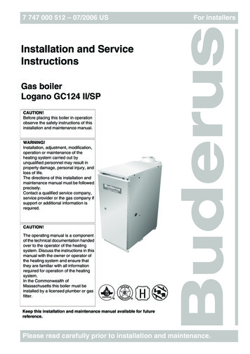
4.0)MINIMUM CLEARANCES TO COMBUSTIBLESCombustible material must be located outside theclearance dimensions listed.Failure to do so may result in death, serious injury orproperty damage.Minimum clearances to combustibles shall be measured from the outer surfaces as shown in the followingdiagram. For reduced clearances below the heater, use the Deflector Kit (Part No. 43504010), described inSection 6.1), and maintain the minimum clearances specified in the notes below. Follow the instructionspackaged with the kit for installation.EndEndCeiling* CeilingFrontSideSideBelowBelow45 Angle (Maximum)HorizontalModel No.SIR 25SIR 35, 45RearMINIMUM CLEARANCES TO COMBUSTIBLESMounted HorizontallySidesCeiling1Below2Ends8”4”41” *8”12”4”57” **8”Angle Mounted at 45º45º45º Front 45º Rear30”4”40”4”1The clearance is 12” when installed in an UNVENTED configuration in industrial and commercial installations.2IN CANADA,CANADA clearances below the heater are:SIR25:36” (27” with deflector);SIR35/45:48” (36” with deflector)* The clearance is 33” with deflector.** The clearance is 42” with deflector / 30” side clearance with deflector. WARNING: Certain materials or objects,objects, when stored under the heater, will be subjected to radiant heat andcould be seriously damaged. Observe the Minimum Clearances to Combustibles listed in the manual and on theheater at all times.NOTE:1. The clearances specified above must be maintainedmaintained to combustibles and other materials that may bedamaged by temperatures 90ºF above ambient temperature. Clearances to combustibles are posted on thecontrol box. In areas used for storage of combustible materials where they may be stacked below the heater,heater,NFPA54 requires that the installer must post signs that will “specify the maximum permissible stacking heightto maintain the required clearances from the heater to combustibles.” SunStar recommends posting these signsadjacent to the heater thermostat or other suitable location that will provide enhanced visibility.2. The stated clearance to combustibles represents a surface temperature of 90 ºF (32 ºC) above roomsiding,ng, canvas, tritemperature. Building materials with a low heat tolerance (such as plastics, vinyle siditri-ply, etc.)may be subject to degradation at lower temperatures. It is the installer’s responsibility to assure that adjacentmaterials are protected from degradation.-4-Form 43471010Sept 2011
5.0)ModelNo.SIR 25SIR 35SIR 45SPECIFICATIONSHeatTotalBtu/hr Exchanger Heater Flue Restrictor PlateInputLength LengthI.D. & Part #25,0007/8” 1/8” #42741031Minimum *Mounting Height@@Natural GasPropane GasHorizontal 45º Angle#42 (0.094) 1.45mm (0.057)8’8’#35 (0.110) 1.75mm (0.069)8’8’1/8” (0.125) 5/64” (0.078)8’8’Orifice Size* MOUNT HEATERS AS HIGH AS POSSIBLE. Minimums are shown as a guideline for human comfort and uniformenergy distribution for complete building heating applications. Consult your SunStar representative for theparticulars of your installation requirements.TypeGasNaturalor PropaneGas PipeConnection½” MPT(Male)TubeDiameterFlueConnectionFresh AirConnection3”4” Round4” RoundFuse Rating:Spark Module: 2 Amp 250V(for 24V Circuit)6.0)ElectricalSupply120 Volt, 60Hz,1 PhaseCurrentRating2.6 AmpIgnition System (direct spark):30 second pre-purge periodPACKING LISTA. Control/Draft Inducer PackagePart DescriptionQTYControl Box Assembly . 1Draft Inducer Assembly (with 4” Starting Collar #40504020) . 1Flue Restrictor Plate (refer to 5.0) for I.D. & part number). 115” Plastic Vacuum Air Tube (#03988150). 1Control Fastener Kit (#42787000) . 1Containing:¼ - 20 Locknuts (#02167010) . 6Gas Connector 5/8” OD x 36” (#30302360) . 1Installation & Operation Instructions (#43471010) . 1CONTROL/DRAFT INDUCER PACKAGE NUMBERSNATURAL GASPROPANE GASMODEL NO.PART NO.MODEL NO.PART NO.SIR25-N5 . #43501030SIR25-L5 . #43501040SIR35-N5 . #43501050SIR35-L5 . #43501060SIR45-N5 . #43501070SIR45-L5 . #43501080B. Body Package DescriptionsPart DescriptionQTY#43468000, 8Ft. Body Package . 1Containing: #43469000, Pre-assembled 8’ ALC steel tube assembly with reflectors . 1#42762010, Control End Reflector . 1#42761010, Foot End Reflector . 1#02125130, #10-24x1/2 Screws . 4#02266010, Speed Clips . 14#42769010, Sliding Clamps . 4Form 43471010Sept 2011-5-
6.1)ACCESSORY PACKAGESA. Exhaust Hood Package, Part #429240006 (15cm)7 1/2 (19cm)3 3/4 (10cm)Contains:Exhaust Hood Assembly, #42925540 QTY–1#8-18 x ½ Self-Drilling Screws, #02189030 QTY–23 1/2 (9cm)4 (10cm)BirdScreenFront ViewSide ViewB. Deflector Kit, Part #4350401#43504010The Deflector Kit is available for use to reduce theclearances to combustibles below the heater. Referto the Minimum ClearancesClearances to Combustibles Table inSection 4.0) when using this Deflector Kit. Heatermust be mounted ONLY in the horizontal positionwhen using this kit.5 1/2 (140mm)Deflector10 1/2 (267mm)Hanger Bracket(tube & reflectorcomponents notshown)DeflectorBracketDeflector-6-Form 43471010Sept 2011
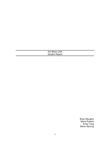
7.0)DIMENSIONS – SIR SERIES111 (280cm)15 (381mm)10 1/2 (267mm)80 (203cm)5 1/2 (140mm)Side ViewReflector5 1/4 (133mm)Hanger Bracket(QTY-2)Emitter Tube18 1/2 (470mm)Bottom View7 1/2 (191mm)8 FT Body Section9 (23cm)Draft Inducer(vertical mounting)Strain ReliefBushingMotorLeads8 (20cm)ControlBox7 (18cm)1/4 O.D.TubePlastic Vacuum SightAir TubeGlassEnd ViewForm 43471010Sept 2011-7-ElectricalConnection8 (20cm)1/2 MPTGas Connection
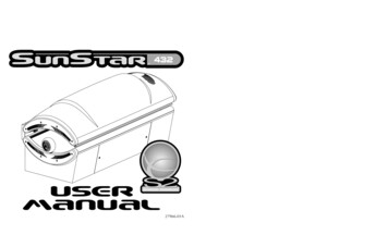
ExhausterassemblyRestrictorairplate-8-Control BoxMounting flange(6-hole)Reflector, control endReflectorMounting flange(3-hole)Reflector clampwith screwU bolt clamp &5/16 Hex nuts3 (control box to reflector)Suspension chainwith turnbuckle5-1/2 (control box to chain)3 OD x 8 tube80 Tube support/hanger bracketU bendReflector, foot end10-1/2 Control boxSide View3 5-1/2 reflectorSuspensionchain8.0)HEATER ASSEMBLY OVERVIEWForm 43471010Sept 2011
9.0)TYPICAL SUSPENSION METHODSSUSPENSION HAZARDBurner must be secured to the mounting flange with nuts.All materials used to suspend the heater must have a minimum working loadof 115 lbs.All S Hooks must be crimped closed.Never use the heater to support a ladder or other access equipment.Failure to do so may result in death, serious injury or property damage.Various means of suspending the heater can be used. See the following drawings for typical examples.1. Use only noncombustible materials for suspending hangers and brackets.2. A minimum No. 2 chain with a working load limit of 115 lbs. is required.3. Turnbuckles can be used with chains to allow leveling of the heater. All “S” hooks and eye bolts must bemanually crimped closed by the installer.4. When using rigid means for heater suspension (rod, flat bar, etc.) provide sufficient lengths or swing joints tocompensate for expansion. See Figures b and c.5. Heaters subject to vibration must be provided with vibration isolating hangers.6. Heaters must not be supported by gas or electric supply lines and must be suspended from a permanentstructure with adequate load capacity.SunStar recommends that the tube sections be suspended using chains with turnbuckles. This will allow slightadjustments after assembly and heater expansion/ contraction during operation.If a “trapeze” method is used for tube support/hanger brackets (shown below), the minimum chain length for thetwo connecting chains is 36” to minimize any vibration that might be generated by the draft inducer assembly. Ifthese chains must be less than 36”, then do not use the trapeze method and, instead, use individual chains oneach tube support/hanger bracket.MinimumNo. 2 ChainThreadedRodEyebolt3/16 x 1 wideFlat BarTurnbuckleincm)M91 (imumS-Hook(typical)a.Form 43471010Sept 201136Eyebolt) MinEyebolt91cmMinimumNo. 2 Chain36 (imumTurnbuckleb.c.d.-9-
10.0)HEATER ASSEMBLYCUT HAZARDSheet metal parts, particularly reflectors and vent have sharpedges. Always use gloves when handling.Failure to do so may result in death, serious injury or propertydamage.During field assembly of the heater, the recommended procedure is as follows:1. Put the suspension in place (according to Section 7.0) using proper suspension method (see Section 9.0).80 80 SuspensionChain11118-1/2 18-1/2 chains for suspensionTrapeze MethodIndividual Suspension Method2. Lift the tube section and suspend it into place. When lifting, caution should be used to avoid damaging theassembly. Make sure that the long axis of heater is level.222Tube Flange2The long axis of heaterLevel indicatorSide View-10-Form 43471010Sept 2011
3. Assembly the reflector onto the tube section. Leave 3” space between the tube flange and the reflector forlater mounting of control box and draft inducer.4. Place the flanges of the control end reflector flush with the end of the first reflector. Secure by sliding speedclips onto reflector edges. Evenly space 6 speed clips on sides and top of reflectors to provide a snug fit.Place foot end reflector on the opposite end of the reflector and secure as above.43Tube FlangeSpeedClipSuspensionchain3 3 4reflectorSide View5. Attach the control box to the right-hand control tube flange and secure with 1/4-20 locknuts. The control boxmust be mounted with the perforated fresh air plate on top, facing the ceiling.6. Attach the draft inducer assembly to the left-hand draft inducer tube flange and secure with 1/4-20 locknuts.A flue restrictor plate is attached to the draft inducer weld studs. Make sure this remains in place while thedraft inducer is being attached to the heater body.6Flue RestrictorPlateDo Not Discard.Tube Flange(draft inducer)Draft Inducer(vertical position)1/4-20LocknutsControl BoxTube Flange(control)5AccessPanelForm 43471010Sept 2011-11-
7. Slip the plastic vacuum air tube over the 1/4” O.D. aluminum tube end of the draft inducer and the airswitch probe in the control box. The air tube should be shortened to prevent a downward sag which couldallow condensation build-up in the tube.8. Insert motor lead wires through the strain relief bushing of the control box and connect to L1 and L2 ofterminal block. Refer also to the wiring diagram in Section 13.0).8Strain ReliefBushing1/4 O.D.TubeMotor Leads(to L1 and L2 ofthe terminal block)7Plastic VacuumAir Tube9. Fasten the reflector to the tube support/hanger bracket with (2) #10 sheet metal screws according to Detail“A”. Mount the sliding reflector clamps (#42769010) per Reflector Clamp Installation (Detail “B”) on bothtube support/hanger brackets. Make sure the reflector can slide under the clamp during heater operation.The reflector clamps MUST be installedinstalled per reflectorclamp installation detail which allows the reflector toslide under the clamp during heater operation.DETAIL B ReflectorClampReflector9ClampScrewTube Support &Hanger BracketReflector Clamp InstallationSee Detail B 9DETAIL A 9Fasten screws to tubehanger/support bracket and reflector(only the tube hanger/supportbracket closest to the control end)9See Detail A & B #10 x 1/2 SHEET METALSCREWS (QTY - 2)Do not relocate the tube support/hanger bracket at the control box end ofthe heater. This will increase the weight on the emitteremitter tube and can resultin premature tube failure.-12-Form 43471010Sept 2011
ANGLE MOUNTED HEATERS ONLY10. The heater can be mounted horizontally or up to an angle of 45º maximum from horizontal. When the heateris to be angle mounted adjacent to a sidewall, make sure the draft inducer assembly is on the lower side ofthe heater so that the control box access panel is easily accessible. Make sure the long axis of heater is level.Multiple draft inducer positions can also be used as shown in the diagrams. This allows for the desiredconfiguration of flue venting.Vertical45 Deg. (maximum)HorizontalHorizontal Mounting11.0)Angle MountingGAS CONNECTIONS AND REGULATIONSTighten flexible gas hose and components securely.Flexible metal gas hoses must be installed without any twists orkinks in them. The hose will move during operation of the heaterand it can crack if it is twisted.Failure to do so may result in death, serious injury or propertydamage.IMPORTANT BEFORE CONNECTING THE GAS TO THE HEATER1. Connect to the supply tank or manifold in accordance with the latest edition of National Fuel Gas Code (ANSIZ223.1), and local building codes. Authorities having jurisdiction should be consulted before the installationis made. (In Canada, refer to the latest edition of CSA Standard B149.1, Natural Gas and PropaneInstallation Code.)2. Check that the gas fuel on the burner rating plate matches the fuel for the application.3. Check that the gas supply piping has the capacity for the total gas consumption of the heaters and any otherequipment connected to the line.4. Check that the calculated supply pressure with all gas appliances and heaters operating will not drop belowthe minimum supply pressure required for these heaters. Check inlet supply pressures on Section 12.0).5. All gas supply lines must be located in accordance with the required clearances to combustibles from theheater as listed on the clearances label of the heater and Section 4.0) of this manual.6. Pipe joint compounds must be resistant to the action of liquefied petroleum gases.7. Tube heaters will expand/contract during operation. Where local codes do not prohibit, a CSA or U.L.approved flexible connector supplied with this heater is required for connections between the rigid pipingand the heater. A union should be installed before the control box inlet. An approved shut off valve should beinstalled within 6 feet of the union.8. The gas pipe, flexible hose and connections must be self supporting. The gas pipe work must not bear any ofthe weight of the heater or any other suspended assembly.9. This appliance is equipped with a step-opening, combination gas valve. The maximum supply pressure to theappliance is 14” W.C. or 1/2 P.S.I. If the line pressure is more than the maximum supply pressure, then asecond stage regulator which corresponds to the supply pressure must be used.Form 43471010Sept 2011-13-
10. After all gas connections have been made, make sure the heater and all gas outlets are turned off beforethe main gas supply is turned on slowly.slowly Turn the gas supply pressure on and check for leaks. To check forleaks, check by one of the methods listed in Appendix D of the National Fuel Gas Code.11. If a 2nd stage regulator is used, the ball valve down stream in the supply line must be closed when purgingthe gas lines to prevent gas seeping through it. If initial gas pressure is higher than 14” w.c. the redundantcombination gas valve is designed to lock out. Pressure build-up in the supply lines prior to the heater mustbe released before proper heater operation.DO not use an open flame of any kind to test
INSTALLATION AND OPERATION INSTRUCTIONS OWNER / INSTALLER: For your safety this manual must be carefully and thoroughly read and understood before installing, operating or servicing this heater. SUNSTAR ECLIPSE INFRARED RADIANT TUBE HEATER Single Stage Pull Through System (Negative Pressure) Models: SIR25, SIR35, SIR45 - (N5/L5)