Transcription
TRADE OFPipefittingPHASE 2Module 4Pipe InstallationUNIT: 1Introduction to Pipe Installationand Safety
Produced byIn cooperation with subject matter expert:Finbar Smith SOLAS 2014
Module 4– Unit 1Introduction to Pipe Installation & SafetyTable of ContentsUnit Objective . 1Learning Outcome . 21.0Pipe Installation on Site . 31.1 Safety Concerns for On Site Work . 31.2 Guidelines to Be Observed For Safe Site Work . 41.3 Hazardous Activities Undertaken During Pipe Installation . 51.4 Procedures for Drilling Building Structures . 51.5 Procedures for Working in Excavations. 61.6 Using Permit to Work Forms. 72.0Hazards Associated with Piping Systems . 82.1 Hazards Associated with Piping Services . 82.2 Colour Coding for Piping Systems . 92.3 MSDS Sheets . 112.4 Tying Into a Live Piping System . 133.0Safety at Heights and in Confined Spaces . 153.1 Working at Heights . 153.2 Equipment Used for Working at Heights . 163.3 Correct Use of a Personal Safety Harness . 213.4 Identifying Confined Spaces and Their Hazards. 233.5 Working in Confined Spaces . 24Exercises . 26Additional Resources . 27Pipefitting Phase 2Revision 2.0 September 2014
Module 4– Unit 1Introduction to Pipe Installation and SafetyUnit ObjectiveThere are six Units in Module 4. Unit 1 focuses on Introduction to PipeInstallation and Safety, Unit 2; Piping Services, Unit 3; Electricity on Site, Unit4; Bracket Fabrication, Unit 5; Ancillary Piping Equipment and Unit 6; Pipingsystem assembly.In this unit you will be introduced to pipe installation on site and the safetyprecautions required when completing this type of work.Module 4PipeInstallationUnit 1Unit 2Unit 3Unit 4Unit 5Unit 6Introductionto Pipeinstallationand SafetyPipingServicesElectricity pingSystemAssemblyImportant NoteThe following unit cannot be used as a substitute for formal safety training.Candidates must complete formal SafePass training as well as certified trainingand instruction for the use of specific MEWP equipment, safety equipmentand confined spaces training for working in hazardous areas, as required bytheir employer and the laws of this land.Pipefitting Phase 2Revision 2.0 September 20141
Module 4– Unit 1Introduction to Pipe Installation and SafetyLearning OutcomeBy the end of this unit each apprentice will be able to: Describe the key safety concerns associated with pipe installations on asite as opposed to working in the controlled environment of aworkshop. List the activities of pipe installation for over ground, underground,high pressure and low pressure piping systems. Describe the potential hazards associated with drilling and excavatingwall and floors with respect to buried or concealed services Identify the key requirements for permit to work forms and how to fillout a generic work permit form. Describe the hazards associated with the following piping systems,steam, compressed gases, water, chemicals, solvents and fuel oil. Describe how colour coding systems are used to identify the contentsof ‘live’ piping systems. Describe the purpose of Material Safety Data Sheets (MSDS) and howthey provide procedures for handling or working with that substance ina safe manner. Describe the key safety concerns with tying into a live piping system Describe the different types of equipment for working at heights, statetheir applications and describe their limitations. Demonstrate how to fit a safety harness and lanyard and list the preuse safety checks to be performed before using one. Describe the potential hazards associated when working in confinedspaces or in deep excavations and what precautions must be takenPipefitting Phase 2Revision 2.0 September 20142
Module 4– Unit 1Introduction to Pipe Installation and Safety1.0 Pipe Installation on SiteKey Learning Points Identify the different safety concerns when working on sitescompared to working in a controlled workshop environment.1.1 Identify safe guidelines when working on site Identify typical activities completed when installing pipe work onsite Identify the hazards associated with drilling or excavating and howto minimize themSafety Concerns for On Site WorkConstruction sites are among the most dangerous and risky workingenvironments. Building infrastructure involves a wide array of processes, alongwith potentially hazardous materials and equipment, so employers have toimpose construction-site safety rules in an attempt to keep accidents andmishaps from taking place. While standard safe working practices and rulesstill apply, working on sites exposes the individual to a complete new set ofrisks and hazards which are not experienced in a controlled workshopenvironment. Some general principals to be observed when organising workon site can be stated as follows: The work must be designed in such a way that any risk to life andhealth is avoided as far as possible and the remaining danger isminimized. Dangers must be combated at source and risks eliminated. PPE shouldonly be used as a second line of defence. Suitable instructions and training must be given to all employees andvisitors to sites. At all times the employer and the employee should strive to ensure thatstate of the art occupational medicine and hygiene and other soundknowledge according to the relevant codes of practice are taken intoaccount. Work should be planed and provide with an appropriate link betweenavailable technology, work organization, other working trades andworking conditions that influence the environment of the workplace. Individual protective measures should take second priority to the safetyof the collective group.Pipefitting Phase 2Revision 2.0 September 20143
Module 4– Unit 11.2Introduction to Pipe Installation and SafetyGuidelines to Be Observed For Safe SiteWorkThe following are basic precautions to be observed when working onconstruction sites. (Please note that this is not an exhaustive list andconsultation with the Site safety officer is critical before any work shouldcommence): Be aware that a construction site is a changing environment and thatnew hazards are appearing and changing all the time. Pipe fitters should complete site inductions to be aware of prevailingsite conditions before commencing any work Obey permit to work systems as site conditions may change from dayto day The primary goal should be to eliminate the risk rather than protectagainst it. Correct PPE equipment should be worn, however this should be thesecond line of defence. Be aware of site traffic, machinery and equipment. Make eye contactwith the driver and wait for a signal that is OK to proceed in mobileplants’ pathway. Be aware of the other trades working on site as these will have differentgoals to be achieved which will sometimes conflict with your goals. Be aware when working at heights and take appropriate safetyprecautions. Be aware when working in excavations and take appropriate safetyprecautions. Be aware when working in confined spaces and take appropriate safetyprecautions. Report all incidents / accidents no matter how minor so that otherpeople can learn from the experience and hopefully not repeat thesame mistake. Obey all safety signage and never assume that you know better. Obey the site policy on smoking and only smoke in designated areaswhich should be designated with proper signage. In the event of an emergency evacuation you should follow the preplanned procedures and report directly to your assigned muster pointleaving your work place and equipment is a safe state. Remain at the muster point to ensure that you have been accounted forand remain there until the all clear has been given to return to thebuilding. Follow instructions. Do not take chances; if you do not know, ASK.,Correct or report unsafe conditions. Help keep the jobsite clean and orderly. Use the right tools andequipment for the job.Pipefitting Phase 2Revision 2.0 September 20144
Module 4– Unit 11.3Introduction to Pipe Installation and SafetyHazardous Activities Undertaken DuringPipe InstallationWhen completing work on site pipe fitters are exposed to many new hazardsand hazardous actives that are not encountered while pipe fitting in a workshop environment: Performing hot works in explosive atmospheres (i.e. solvent or dustladen atmospheres) Tying into live piping systems Working at heights, off ladders or scaffolds Working in confined spaces, trenches or excavations Construction plant and equipment moving around site Working close by to suspended loads and lifting equipment Being exposed to buried services and or electrical cables1.4Procedures for Drilling Building StructuresWhen installing and erecting prefabricated piping, pipe fitters may be requiredto drill holes for bracketing support or core holes through walls to facilitatepipe routes.While large scale opes for multiple pipe runs are usuallycoordinated and provided by the civil contractor pipe fitters may have tocomplete cores for single pipe routes or drill holes to secure brackets whichsupport pipes from floors walls or celings. When dealing with drilling orcoring walls, floors or ceilings the following procedures should be observed: If it is suspected that hidden hazards exist at the point of penetration,relocate the work if possible. If the work cannot be relocated, use non-destructive testing (NDT)devices (ground penetrating radar, x-ray, magnetic, induction,conductive, or other devices and methods) to determine whetheradditional hazards or wall reinforcement exists. For hollow structures a pilot hole may be useful to look for hiddenutilities. Area responsible person/designee, customer/requester, or otherpersonnel consulted? Reviewed historical records, engineering plans, and drawings? Visually inspected proposed location of penetration? Checked other side of walls, under floors, or through false ceilings forhazards? NDT used to determine stud locations or if there are any services, wallreinforcement or if additional hazards exist? De-energized and locked/tagged-out energy sources as required? Non-conductive tools to be used where applicable? Masonry bits and hand tools to be used for initial penetration?Pipefitting Phase 2Revision 2.0 September 20145
Module 4– Unit 1Introduction to Pipe Installation and Safety Drill bits marked, fitted with stops or short drill bits (2 inches or less)to be used for solid material? Appropriate PPE specified and obtained?1.5Procedures for Working in ExcavationsPipe fitters need to be aware of the hazards of excavating or working intrenches before commencing such work. When dealing with work in trenchesthe following procedures should be observed: Contractor shall assign a competent person to all trenching andexcavation work. This person shall be clearly identified to all employeesassigned to the job. Underground lines, equipment and electrical cables shall be identifiedand located by the Contractor Coordinator prior to beginning workthat involves. Contractors will not initiate work without prior approval of theContractor Coordinator. Walls and faces of trenches and excavations, deeper than 1m, shall beshored, sloped or shielded as required by the type of soil encountered. Prior approval from the Contractor Coordinator and EH&S personnelis required before commencing, or continuing, with trenching deeperthan four feet. A confined space entry permit shall be required where oxygendeficiency or a hazardous atmosphere exists or could exist. A stairway, ladder, ramp or other safe means of egress shall be locatedin any trench excavations more than 1m in depth. Daily inspections shall be conducted by a competent person forevidence of a situation that could result in possible caveins, indicationsof failure of protective systems or other hazardous conditions. Employees shall not be permitted underneath loads handled by liftingor digging equipment. Employees shall be protected from excavated or other materials andequipment that could cause a hazard by falling or rolling into theexcavation. Physical barriers shall be placed around or over trenches andexcavations. Flashing light barriers shall be provided at night.Buried services are colour coded to aid identification, some of the morecommon colour coding is as follows:Black or RedElectricityBlueWaterYellowGasGrey or WhiteTelecommunicationsGreenCable TelevisionPipefitting Phase 2Revision 2.0 September 20146
Module 4– Unit 11.6Introduction to Pipe Installation and SafetyUsing Permit to Work FormsThis is a duplicate of Module 1 Unit 3 Health and safety section 6.0Pipefitting Phase 2Revision 2.0 September 20147
Module 4– Unit 1Introduction to Pipe Installation and Safety2.0 Hazards Associated with PipingSystemsKey Learning Points Identify hazards associated with piping services Identify how colour coding for piping systems operate Identify the purpose of MSDS sheets Identify hazards of tying into live piping systems2.1Hazards Associated with Piping ServicesWith numerous different piping services there are numerous different hazardsassociated with each service. Table 1 below identifies some risks common tothe following services and the method used to minimise the risk Steam Chilled water Compressed Gases Water Chemical / Solvents Fuel oilServiceRiskMethod to minimise riskSteamHeat BurnsInsulation and cladding.High pressure leakHigh pressure pipe and fittings.Steam gaskets.Chilled waterFreeze BurnsInsulation and cladding.Compressed gassesGas leaksHigh pressure pipe and fittings.Certified welding procedures.AsphyxiationOxygen monitors and alarmsstrategically located in processareas to detect leaksHeat burnsInsulation and cladding.High pressure leakHigh pressure pipe and fittings.Certified welding procedures.WaterPipefitting Phase 2Revision 2.0 September 20148
Module 4– Unit 1Chemical / SolventsIntroduction to Pipe Installation and SafetyCorrosionHeavy wall pipe and fittings.Special corrosion resistant alloymaterial e.g. stainless steel orHastelloy.AsphyxiationOxygen monitors and alarmsstrategically located in processareas to detect leaks.ATEX ratedinstruments.ExplosionvalvesandHigh pressure pipe and fittingsFuel OilExplosionATEX rated valves andinstruments.High pressure pipe and fittings.Excess pressureFit safety relief valve to systemclose to the system pump.Ensure there are no valvesfitted to vent lines.Table 1 – Risks associated with piping services and methods of Risk minimisation2.2Colour Coding for Piping SystemsPiping systems are an important means of conveying liquids, gases, steam andair. It is however impossible to find out what a pipeline contains from itsexternal appearance. As the number and complexity of piping systems withinany facility increase, so does the need for a system to quickly and easily identifypipework, pipelines and their contents. Failure to correctly identify the serviceof a pipework system can and often has been shown to be the cause of plantupsets and safety incidents. Effective identification of all pipework eliminatesthe potential of such problems occurring. Colour coding labels can alsoinclude arrows to indicate the direction of flow.Standards Used for Colour CodingWhile different colour coding systems and standards are applicable in differentcountries and different industries, the following information is based on thefollowing British standard specifications: BS 1710 Identification of Pipelines and Services BS 381C Colours for Identification, Coding and Special Purposes BS 4800 Paint Colours for Building PurposesIt is important that you familiarise yourself with the colour coding system thatis specific to the facility that you are working in as there may be slightdifferences or variations that could have serious consequences if the incorrectpipe is selected by colour alone.Pipefitting Phase 2Revision 2.0 September 20149
Module 4– Unit 1Introduction to Pipe Installation and SafetyThe Basic/Primary Identification Band (PIB) colour determines the basic typeof fluid, e.g. Oil, Gas, Chemical or Water. BS 1710 suggests BasicIdentification Colours for different types of fluid. BS 1710 specifies blue as thePIB colour for air, green for water, brown for oils, ochre for gases, purple foracids and alkalis, silver grey for steam, black for drainage systems and red forfire fighting systems. It should be noted that steam pipework, is generallyinsulated and fitted with silver coloured metal cladding.Table 2 – Basic identification coloursA Safety/Secondary Identification Band (SIB) colour is added to the middle ofthe PIB, to identify the fluid conveyed more precisely. The SIB, used inconjunction with the PIB’s, is designed to provide a unique combined ColourCode Identification Band (CCIB) for each fluid that is being conveyed.Table 2 – Safety coloursPipefitting Phase 2Revision 2.0 September 201410
Module 4– Unit 1Introduction to Pipe Installation and SafetyThe Primary Identification Band (PIB) and the secondary Identification Band(SIB) are combined to produce a unique Three Band Colour CodeIdentification Band System (CCIB), as specified in BS 1710. The outer bands,which will be the same colour, are the Basic/Primary Identification Bands(PIB) and the middle band is the Safety/ Secondary Identification Band (SIB).Examples of this are illustrated in Figure 1 below.Figure 3 – Pipework Colour Coding band layoutAdvantages of Colour Coding Piping SystemsColour coding of piping systems have the following advantages: It allows for easy identification of services in piping systems. It facilitates the tracking of lines at height from ground level. It is a GMP, ISO requirement. Colour coding is helpful for illiterates. Easy and accurate form of communication. It can reduce accidents and improve safety.2.3MSDS SheetsA material safety data sheet (MSDS) is a form containing data regarding theproperties of a particular substance. It is intended to provide workers andemergency personnel with procedures for handling or working with thatsubstance in a safe manner, and includes information such as physical data(melting point, boiling point, flash point, etc.), toxicity, health effects, first aid,reactivity, storage, disposal, protective equipment, and spill-handlingprocedures. MSDS formats can vary from source to source within a countrydepending on national requirements.In some jurisdictions the MSDS is required to state the chemical's risks, safety,and effect on the environment. There is also a duty to properly labelsubstances on the basis of physico-chemical, health and/or environmental risk.Labels can include hazard symbols such as the European Union standard blackdiagonal cross on an orange background, used to denote a harmful substance.Pipefitting Phase 2Revision 2.0 September 201411
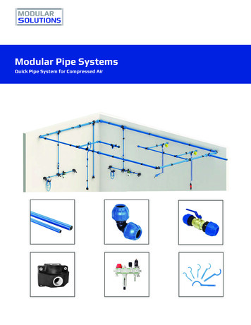
Module 4– Unit 1Introduction to Pipe Installation and SafetyAn MSDS for a substance is not primarily intended for use by the generalconsumer, focusing instead on the hazards of working with the material in anoccupational setting. It is important to use an MSDS specific to both countryand supplier, as the same product (e.g. paints sold under identical brand namesby the same company) can have different formulations in different countries.The supplier must by law supply accurate MSDS sheets for any chemicals thatthey supply. Figure 2 below shows page 1 of a 10 page MSDS sheet for Gasoiland illustrates the typical information which they contain.Figure 2 – Page 1 of 10 of MSDS sheet for GasoilPipefitting Phase 2Revision 2.0 September 201412
Module 4– Unit 12.4Introduction to Pipe Installation and SafetyTying Into a Live Piping SystemPiping tie-ins are unavoidable in plants where expansion is a current or futurefactor. Steam, condensate, compressed air, dust collection, vacuum and processlines are just a few types of plant piping likely to be modified by tie-ins toincrease capacity. Here are a few ways to minimize costly disruption of plantoperation when tie-ins are inevitable. Plan and schedule. New piping design should include allowances forfuture expansion. This can be accommodated without major expense.Consider the following: Increase design pipe sizes to the next larger diameter if velocity limitspermit. Provide caps or blind flanges at the end of a pipe run where a brief tiein outage can be tolerated. Provide valves with blind flanges when and where a future tie-in outagecannot be tolerated. Provide adequate access and maintenance space for future connectingpiping.Existing piping design may provide limited flexibility for future piping tie-inaccommodations. However, take advantage of future scheduled outages andadd piping flanges and valves where future tie-ins are inevitable. This willenable future construction to proceed without disrupting plant and processoperations.Completing Tie-In on SiteFor precautionary reasons, issue a line break permit to address specific detailsof the procedure prior to construction. The purpose of the permit is to define: Location of the line break. Applicable design documents. Fluid in the line. Safety equipment requirements. Hazards associated with handling the materials last in the line. Special line washing, purging or flushing requirements. Valve locking and tagging requirements. All personnel involved or affected by the procedure. Installation of the connecting piping is simplified if provisions aremade in the piping for isolating the tie-in point. Piping installation canthen occur without disrupting the process.“Hot Tapping”When a tie-in point on a line cannot be isolated or the plant or process cannotbe shut down to accommodate the line break, a procedure known as “hottapping” is required. This is frequently used to break lines containing steam,natural gas, water or other utilities, which must flow uninterrupted on a dailyPipefitting Phase 2Revision 2.0 September 201413
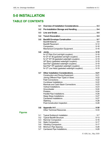
Module 4– Unit 1Introduction to Pipe Installation and Safetybasis. This procedure results in the installation of a lockable tie-in valve whilethe line is pressurized.Figure 3 below identifies the essential equipment required for a hot tappingprocedure including hot tap fitting, full open and lockable gate valve, hot tapmachine (hydraulic or air-driven), cutter and pilot assembly, tapping machinehousing, a power unit (hydraulic or air-driven) and hose. Basic hot tappingsteps include: Weld the hot tap fitting onto the line. Install the full open gate valve on the fitting. Inspect and pressure test the valve and fitting. Install the hot tap machine on the valve. Bore the line. Retract the boring bar, then close and lock the valve. Depressurize the hot tap machine and remove it. Clean the work area.Figure 3 – Schematic of a hot tapping machineHot tapping is a unique, specialized procedure. Only companies experienced inthis technique should be considered to perform this procedure. Often, thesecompanies perform other tasks such as line stops, repairs, cleaning and valvereplacement.Following the hot tapping procedure, installation of connecting piping valvesand fittings can proceed in much the same manner as though existing isolationprovisions were already in the line. Once installation is complete, conduct apressure and leak test of the newly installed piping with the tie-in valveremaining in the closed and locked position. With satisfactory pressure testcompletion, the new tie-in piping is now ready to be activated by unlockingand opening the tie-in valve.Pipefitting Phase 2Revision 2.0 September 201414
Module 4– Unit 1Introduction to Pipe Installation and Safety3.0 Safety at Heights and in ConfinedSpacesKey Learning Points Identify where working at heights occurs3.1 Identify how to mitigate the risks of working at heights Identify equipment used for working at heights Identify how to use a safety harness correctly Identify the potential hazards when working in confined spacesWorking at HeightsWork at height is work in any place, including a place at, above or belowground level, where a person could be injured if they fell from that place.Access and egress to a place of work can also be work at height.Examples of work activities that are classified as working at height: Working on trestles Working on a flat roof Erecting false work or formwork Working on a ladder Working at ground level adjacent to an excavation; Working on formwork within an excavation Working near or adjacent to fragile materialsBefore carrying out work at heights it is important to complete the following: Carry out risk assessments for work at height activities and make surethat all work is Planned, Organised and carried out by a competentperson Follow the General Principles of Prevention for managing risks fromwork at height – take steps to avoid, prevent or reduce risks Chose the right work equipment and select collective measures toprevent falls (such as guard rails and working platforms) before othermeasures which may only reduce the distance and consequences of afall (such as nets or airbags) or may only provide fall-arrest throughpersonal protection equipment.The Work at Height Regulations require employers to ensure that: All work at height is properly planned and organised A risk assessment is carried out for all work conducted at height Appropriate work equipment is selected and used People working at a height are competent and trainedPipefitting Phase 2Revision 2.0 September 201415
Module 4– Unit 1 Introduction to Pipe Installation and SafetyEquipment used for work at height is properly inspected andmaintained Risks from fragile surfaces are properly controlledThe risk assessment should include a careful examination of what harm couldbe caused from working at height with a view to taking the effective steps toreduce the likelihood of this harm occurring, either through avoiding theactivity or, where this is not reasonably practicable, by carrying it out in a safemanner using work equipment that is appropriate to the task and the level ofrisk.3.2Equipment Used for Working at HeightsLaddersThe Work at Height Regulations do not ban ladders but require considerationto be given to their use. They require that ladders should only be considered; Where the use of other more suitable work equipment such as towerscaffolds, MEWPs or temporary stairs is not appropriate, Ladders, forexample, are frequently used during fit-out installations, but in mostcases other work equipment is more appropriate. Where ladders and stepladders are used they should only be used as awork place for light work that is low risk and of short duration.Always: Have 3 points of contact when using a ladder Make sure ladder has non-skid pads ‘Ladder Stopper’ Do:Test pullies, springs, rung locks and ropes on extension ladders Use a ladder ‘Stopper’ Tie off top of ladder if possible Move the ladder Get a taller ladder when required Get down and move the ladder Use a Tool BeltDon’t: Overreach from a ladder Use the top two rungs Move a ladder while on it Climb with material Share a ladder Set up near live cables.Pipefitting Phase 2Revision 2.0 September 201416
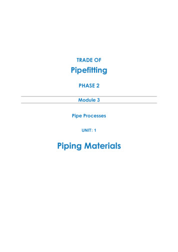
Module 4– Unit 1Introduction to Pipe Installation and SafetyExtension Ladders A minimum of 1 meter overlap is required between ladders Secure at the top where possible Area around ladder cordoned off, to keep the public safe. Extend ladder 1m (3 rungs) above landing place Follow the 4:1 rule when using extension laddersFigure 4 – Safe set-up of an extension ladderMEWPsMobile Elevated Working Platforms(MEWPs) are used to providetemporary access for people orequipment to inaccessible areas,usually at height. There are twodistinct types of mechanized accessplatforms which are known as a"scissor lift" or a "cherry picker".They are designed to lift personneland equipment of limited weights(usually less than a ton, althoughsome have a higher safe workingload (SWL). They are usually capableof being fully operated (includingsetup) by a single person.Figure 5 – MEWPs: Scissors lift andcherry picketPipefitting Phase 2Revision 2.0 September 201417
Module 4– Unit 1Introduction to Pipe Installation and SafetyAdvantages of MEWPsMEWPs have the following advantages when working at heights: Can be used in-doors or out Allow the worker to reach the task quickly and easily Provide a secure stable platform for personnel, materials andequipment which can be quickly moved to different locations.Choosing the Right MEWP for The JobIf you are thinking of using a MEWP look at the following questions. Height; how high is the job from the ground? Application; do you have the appropriate MEWP for the job? (If youare not sure, check with the hirer or manufacturer.) Will the platformbe used to lift equipment and materials? Conditions;
3.0 Safety at Heights and in Confined Spaces . 15 3.1 Working at Heights . 15 3.2 Equipment Used for Working at Heights . 16 3.3 Correct Use of a Personal Safety Harness . 21 3.4 Identifying Confined Spaces and Their Hazards . 23 3.5 Working in Confined Spaces . 24 Exercises . 26 Additional Resources . 27. Module 4- Unit 1 Introduction to Pipe Installation and .