Transcription
Room Sensor and ThermostatMounting and Maintenance Application GuideContentsKMC Room Sensors and Thermostats.1Handling Precautions.2Mounting Plates/Adapters.2Mounting for Optimal Temperature Sensing.3Mounting for Optimal Motion Sensing.4Mounting Height.5Troubleshooting (Location).6Reducing Temperature Sensing Errors.6Maintenance.8Important Notices.9Support.9KMC Room Sensors and ThermostatsKMC Controls manufactures a variety of pneumatic, analog electronic, anddigital room sensors and thermostats. Some sense only temperature, whileothers also add humidity, motion, and/or CO2 sensing. This document coversgeneral principles for mounting and maintenance of room (temperature,humidity, motion, and CO2) sensors.KMC also sells other kinds of sensors (e.g., duct, air flow, smoke, carbonmonoxide, pressure) that are not covered by this document.For additional general information about sensors, see the following informationon the KMC web site. Sensor and Thermostat Selection Fundamentals White PaperSensor and Thermostat Selection GuideHow Hot Do You Feel? (Humidity Effects, Sensing, and Control)(CO2) Demand Control Ventilation Benefits for Your Building White PaperKMC Controls, 19476 Industrial Drive, New Paris, IN 46553 / 877-444-5622 / Fax: 574-831-5252 / www.kmccontrols.com
Handling PrecautionsFor digital and electronicsensors, thermostats, andcontrollers, take reasonableprecautions to preventelectrostatic discharges tothe devices when installing,servicing, or operating them.Discharge accumulatedstatic electricity by touchingone’s hand to a securely grounded object before working with each device.Mounting Plates/AdaptersFor mounting to various sizes of electrical boxes or other openings, KMCControls sells mounting plates/adapters designed for various models ofsensors.NOTE: Light almond plates are not for white “W” model sensors.For BAC-12xxxx, BAC-4xxxCW000x, and STE-9xxxHMO-10000W White (shown), for mounting BAC12xxxx FlexStats (not needed forBAC-13xxxx/14xxxx models), BAC4xxxCW000x AppStats, and STE-9xxxNetSensors to horizontal 2 x 4 inchhorizontal or 4 x 4 inch electrical boxesHMO-10000 Light almondFor KMD-116x/118x/12x1 and STE-8x01HMO-1161Light almond (shown), for mountingKMD-116x/118x/12x1 and STE-8x01NetSensors to 4 x 4 or horizontal 2 x 4inch electrical boxesHMO-1161W WhiteFor KMD-1151/1171HMO-5042HMO-5043Light almond (shown), for mounting(discontinued) KMD-1151/1171NetSensors to 4 x 4 or horizontal 2 x 4inch electrical boxesWhiteFor STE-6xxx and THE-1102HMO-6036Light almond (shown), for mounting STE6xxx temperature sensors and THE-1102humidity transmitters with temperaturesensors to 2 x 4 inch electrical boxesHMO-6036W White2AG150119F
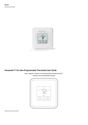
For THE-1105, CTE-51xx, and CTC-16xxNOTE: These backplate kits are for THE-1105 humidity transmitters withtemperature sensors, CTE-51xx electronic thermostats, and CTC-16xxpneumatic thermostats. The kits allow the thermostats to be mountedto 2 x 4 inch electrical boxes or to adapt to Barber-Colman, JohnsonControls, L&G-P, or Robertshaw/Invensys mounting plates.HMO-5024HMO-5026HMO-5030HMO-5031Light almond with aluminum trim (shown)White with aluminum trimLight almondWhiteMounting for Optimal Temperature SensingFor effective temperature sensing, mount the thermostat or sensor in a locationenabling it to sense the general room environment. The thermostat or sensormust NOT be: Blocked from normal air circulation by obstructions (e.g., behind curtains orcubicle walls). Exposed to artifical heat sources (e.g., lights, computers, copiers, or coffeemakers) or to sunlight (at any time of the day). Exposed to drafts from windows, doorways, diffusers, or returns. Exposed to air flow through the conduit (e.g., from leaks in plenum ducts) orother holes into the wall cavity. See Reducing Temperature Sensing Errors onpage 6. Mounted on an exterior wall. See Reducing Temperature Sensing Errors onpage 6. Mounted on or near a large thermal mass (e.g., a concrete block wall). SeeReducing Temperature Sensing Errors on page 6. Mounted in or near a corner. See Minimum Distance from Corners on page 3.NOTE: The above factors primarily affect temperature sensing, but some alsoaffect accurate humidity and CO2 sensing as well.Minimum6 InchesMinimum Distance from CornersAG150119F3
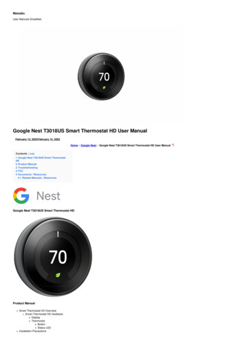
Mounting for Optimal Motion SensingFor motion sensing models, mount the sensor on a wall that will have anunobstructed view of the typical traffic in the coverage area. Some of theissues that affect temperature sensors also affect motion sensors. (SeeMounting for Optimal Temperature Sensing on page 3.) When choosing alocation, the motion sensor must NOT be: Behind curtains or other obstructions. In locations exposed to direct sunlight or heat sources. Near a heating or cooling inlet or outlet.To BASIntegratedMotion andTemp.SensorObstructionMotion SensorTypical Motion Sensing CoverageSituations that would need additional remote motion sensors (third party,purchased separately) to be connected to the controller include: Areas with obstructions that block sensor coverage. Areas too large for adequate coverage by the sensor/thermostat’s single builtin sensor.NOTE: Using remote sensors requires custom programming in mostcontrollers. For information about using integrated and selectableremote motion sensors in a FlexStat, see the FlexStat ApplicationGuide.For KMC motion sensors, the effective detection range is approximately 33 feet(10 meters). Factors that may reduce the range may include the following items. Too small of difference between the surface temperature of the object and thebackground temperature of the room. Object movement in a direct line toward the sensor. Very slow or very fast object movement. Obstructions in the (horizontal or vertical) sensing area. See Typical MotionSensor Pattern on page 5.False detections may be triggered by any of the following conditions. The temperature inside the detection range suddenly changes because of theentry of cold or warm air from an air-conditioning or heating unit. The sensor being directly exposed to sunlight, an incandescent light, or othersource of infrared rays. Small animal movement.4AG150119F
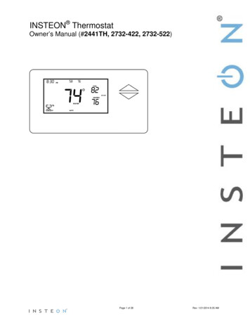
(Side View)(Top View)Typical Motion Sensor PatternMounting HeightSealantPluggingConduitandOtherHolesOptional Insulating GasketBackplateCoverElectricalBoxApproximately60 Inches(Traditional)48 InchesMax. (ADA)Mounting Components and HeightAG150119F5
Traditionally, thermostats and room temperature sensors have been mountedapproximately 60 inches (152 cm) from the floor. This has been consideredan effective height to measure the room temperature and to allow a person toadjust a setpoint while standing.However, for thermostats (and sensors with adjustable setpoint controls), theAmericans with Disabilities Act (ADA) has rules to ensure that public lodgingspaces and facilities remain accessible to the disabled. (They do not applyto private homes that rent fewer than five rooms.) To ensure that people inwheelchairs can reach and adjust the setpoint without assistance, ADA rulesspecify thermostat placement to be no higher than 48 inches (121 cm) above thefloor (assuming no other obstructions are below it).BEFORE running conduit and installing a thermostat, check the specific detailsof any applicable compliance requirements!Troubleshooting (Location)To correct or compensate for sensing problems caused by mounting issues: Reposition the sensor or the surrounding obstructions. See Mounting forOptimal Temperature Sensing on page 3 and Mounting for Optimal MotionSensing on page 4. Insulate the sensor from air leakage and heating/cooling sources. See Reducing Temperature Sensing Errors on page 6 and Mounting Components andHeight on page 5. Adjust the sensor calibration to offset the environmental issues. See theinstructions for the sensor and/or configuration software.Inaccurate sensing may also be caused by one of a variety of electrical orconfiguration issues. See the installation and/or application guide of the sensorfor those factors.Reducing Temperature Sensing ErrorsBest Practices Air movement between the conditioned space and the conduit and/or wall cavity can skew sensor readings. Apply sealant inside the conduit and other holesto block air leakage. See Mounting Components and Height on page 5. Mounting on an exterior wall will allow varying outside conditions to affectthe sensor’s readings. Mounting on or near a large interior thermal mass (e.g.,concrete block wall) can slow the sensor’s response to room air temperaturechanges. These mounting areas should be avoided, but a foam gasket (e.g.,HPO-1161 or HPO-9002) mounted behind the backplate may help insulate thesensor from a less-than-optimal wall surface. See Mounting Insulators onpage 7, Mounting Components and Height on page 5, and the accessoriesavailable for the applicable product.NOTE: A foam gasket may also help block air leakage from the wall cavity.6AG150119F
(HPO-9002) Foam Gasket on a (NetSensor) BackplateNOTE: The notch in the HPO-9002 gasket should match the location of thenotch in the STE-9000 series NetSensor case. (AppStats, on the otherhand, do not have a notch in the case.)NOTE: Older CTE-1000/1100 series thermostats and TTE-1001 transmittershave plastic extenders to help insulate them from the wall’s surface. After reducing environmental issues as much as possible, calibrate the sensor(controller or thermostat input) for maximum accuracy within its environment.See the relevant product calibration procedure to provide the optimal offset.(Wait until the sensor has been operating for at least half an hour beforecalibrating it.) See also Mounting for Optimal Temperature Sensing on page 3.Mounting HMO-5013AG150119FFoam insulating gasket for KMD-116x/118x/12x1and STE-8x01 NetSensors (mounts between theblack backplate and the electrical box)Foam insulating gasket for STE-9xx1 NetSensorsLight almond (shown) backplate extenderand insulator, 1-1/8 inches deep, for CTE1xxx thermostats, CTE-11xx thermostats,and TTE-1001 transmittersWhite, 1-1/8 inches deepLight almond (shown), 1-11/16 inchesdeepWhite, 1-11/16 inches deep7
MaintenanceTo maintain accurate temperature and humidity sensing, remove dust asnecessary from the ventilation holes in the top and bottom of the case.To clean the case or display, use a soft, damp cloth (and mild soap ifnecessary).Clean Case Holes and SurfaceTo maintain maximum sensitivity of the built-in motion sensor, occasionally wipedust or dirt off the lens—but do not use any fluid on the sensor.Clean Motion SensorCO2 sensors designed for continuous occupation applications, such as in theBAC-14xxxx FlexStats, require periodic calibration with gas to maintain long-termaccuracy. See the CO2 calibration section in the FlexStat Application Guide formore information.NOTE: BAC-13xxxx FlexStats and most other KMC CO2 sensors are designedto operate in areas where CO2 levels periodically fall to outside levelsduring unoccupied periods. Such models self-calibrate over time, andcalibrating them with gas may not be necessary or even feasible.8AG150119F
Important NoticesThe KMC logo and KMC Controls are registered trademarks of KMC Controls,Inc. Other products and name brands mentioned may be trademarks of theirrespective companies or organizations.All rights reserved. No part of this publication may be reproduced, transmitted,transcribed, stored in a retrieval system, or translated into any language in anyform by any means without the written permission of KMC Controls, Inc.The material in this document is for information purposes only. The contentsand the product it describes are subject to change without notice. KMCControls, Inc. makes no representations or warranties with respect to thisdocument. In no event shall KMC Controls, Inc. be liable for any damages, director incidental, arising out of or related to the use of this document.SupportAdditional resources for product specifications, installation, configuration,application, operation, programming, upgrading and much more are available onthe KMC Controls web site (www.kmccontrols.com). Log in to see all availablefiles. AG150119F2021 KMC Controls, Inc.Specifications and design subject to change without noticeAG150119E9
temperature sensors, CTE-51xx electronic thermostats, and CTC-16xx pneumatic thermostats. The kits allow the thermostats to be mounted to 2 x 4 inch electrical boxes or to adapt to Barber-Colman, Johnson Controls, L&G-P, or Robertshaw/Invensys mounting plates. HMO-5024 Light almond with aluminum trim (shown) HMO-5026 White with aluminum trim