Transcription
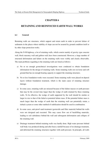
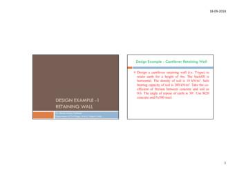
18‐09‐2018Design Example - Cantilever Retaining WallDESIGN EXAMPLE -1RETAINING WALL# Design a cantilever retaining wall (i.e. T-type) toretain earth for a height of 4m. The backfill ishorizontal. The density of soil is 18 kN/m3. Safebearing capacity of soil is 200 kN/m2. Take the coefficient of friction between concrete and soil as0.6. The angle of repose of earth is 30o. Use M20concrete and Fe500 steel.Dr. Hassan Irtaza, ProfessorDepartment of Civil Engg., A.M.U., Aligarh, India1
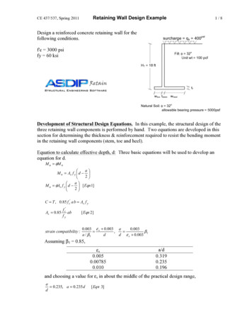
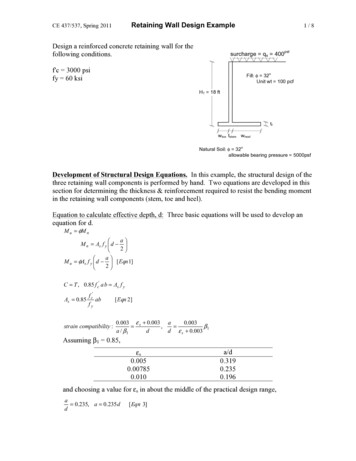
18‐09‐2018# SolutionPROPORTIONING OF WALLData: h' 4mSafe Bearing Capacity of soil 200 kN/m2γ 18 kN/m3, μ 0.6, ø 30oHeight of the retaining wall H h' Df 2SBC 1-sin γ 1 sin 1.23 m say 1.2 mThickness of base slab 1/10thto 1/14th of H [0.52 m to 0.43m] say 450 mmWidth of the base slab 0.5 to0.6 of H [2.6 m to 3.12 m] say3mToe projection 1/3 to 1/4 of B[1m to 0.75 m] say 0.75 mDf Therefore H 5.2 m Provide 450 mm thickness forthe stem at the base and 200 atthe top of the stem.2
18‐09‐2018DESIGN OF STEM1 - sin 1 - sin30o 1 31 sin 1 sin30oPh 1 .K a .γ.H 2 1 1 18 4.752 67.69 kN22 3hM Ph . 67.69 4.75 107.17 kN-m33M u 1.5 M 160.76 kN-mKa Taking 1m width of the vertical ofwall, its thickness is given byB.M. 0.133 σ ck bd 2160.76 106 0.133 20 1000 d 2Adopt a 300 mm effective depth and 350 mm overallthickness of the stem at base and 200 mm thickness at the topof the stem. Area of steel required:σ y .A t M u 0.87σ y A t d σ ck .b 500 A t 160.76 106 0.87 500 A t 300 20 1000 A t 1394mm 2Area of steel required for balanced section:or, d 246 mm3
18‐09‐2018CURTAILMENT OF BARSAt 0.36σck bx m 0.36 20 1000 0.46 300 0.87σ y0.87 500 2284 mm 2 1394 mm 2The section is under reinforcedUse 16 mm diameter TMT bars @ 125 mm c/c[* less than 300 mm and 3d, o.k.]201 1000 125A t provided 1001000 300 0.54% 0.12%Curtail 50% steel from top wherethe moment is 50% of basemoment. Position where the B.M.is half from top 3.77mActual point of cut off 3.77 - Ld 3.77 - 58φbar 3.77 - 0.928 2.85 m from topspacing of bars 250 mm c/c 300 mm and 3d o.k.4
18‐09‐2018Development length (Stem steel)Ld 58 bar 58 16 928 mmSecondary steel for stem at front0.12% GA 0.12 (350 200) 1000 2100 330 mm2#10 bar @ 175 - 200 mm c/c both ways 450 mm and 5d o.k.Distribution steel 0.12% GA 0.12 275 1000 100Check for ShearMax. SF at junction x-x Ph 67.69 kNUltimate SF Vu 1.5 x 67.69 101.535 kNNominal shear stress 101.535 10001000 300 0.34 M Paτ v Vu bd To find τ c : 100A st bd 0.788% 330 mm 2From IS: 456 - 2000#10 mm bar @175-200 mm c/c 450 mm and 5d o.k.τ v τ c , hence safe in shearτ c 0.57 M Pa5
18‐09‐2018STABILITY ANALYSISLoadMagnitude(kN)Distance from A(m)BM about A(kN-m)Stem W10.2x4.75 x1x25 23.750.85 0.15 0.1 1.126.125Stem W2½ x 0.15 x 4.75x1 x 25 8.900.85 2/3 x0.15 0.958.455Base Slab W33.0 x 0.45 x 1 x25 33.751.550.625Back fill W41.8 x 4.75 x 1 x18 153.92.1323.19H/3 5.2/3ΣMR 408.40Mo 140.61TotalΣW 220.30Total HorizontalEarth Pressure PhPh 0.333x18 x5.22/2 81.126
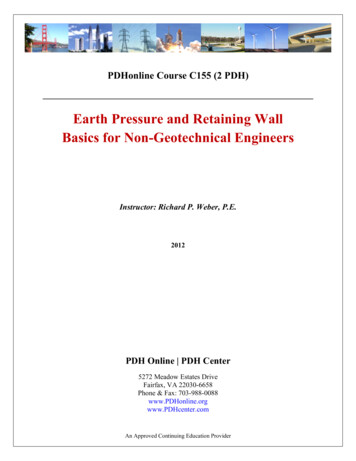
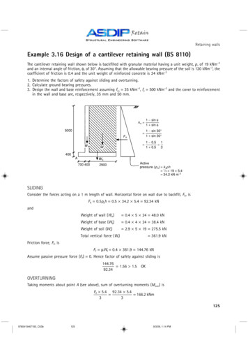
18‐09‐2018Pressure Below the Retaining Wall7
18‐09‐2018Stability ChecksCheck for overturningFOS ΣMR/Mo 408.40/140.61 2.940 1.55 safeCheck for slidingFOS μ ΣW/PH (0.6 x 220.30)/81.12 1.63 1.55 safeCheck for subsidencex ΣM/ΣW (408.40-140.61)/220.30 1.215 b/3and e b/2 - x 3/2 - 1.215 0.285 b/6Pressure below the base slabPmax 115.29 kN/m2 SBC, safePmin 31.57 kN/m2 zero,No tension or separation, safeDesign of Heel SlabW 6e W 6e 1 ,Pmin 1 bl l bl l where, b 1 m, l 3 mPmax 8
18‐09‐2018Design of Heel SlabMagnitude(kN)Distancefrom C (m)BM, Mc(kN-m)Back fill1.8 x 4.75 x 18 153.90.9138.51Heel Slab0.45 x 1.8 x 25 20.250.918.23Upward Pressure(Rectangular portion)31.57 x 1.8 56.830.9-51.15Upward Pressure(Triangular portion)½ x (81.80231.57) x 1.8 45.2071/3 x 1.8-27.12Total Load72.113 KNLoadMu 1.5 x 78.47 117.71 kN-mS.F. 72.113 kNVu 1.5 x 72.113 108.17 kNEffective depth of heel is given asd 117.71 106 210mm0.133 20 1000Adopt an effective depth of 300 mmand overall depth of 350 mm.CΣMc 78.479
18‐09‐2018σyAt M u 0.87σ y A t d σ ck b 117.71 10 6 0.87 500A t (300 -500A t)20 1000A t 982 mm 2Spacing calculated for 16 mm bars 204 mm c/cProvide 16 mm TMT bars @ 150 mm c/c 300 mmand 3d O.K.Pt 0.46% 0.12%Development length Ld 58 φbar 58 x16 928 mmDistributed steelSame, #10@ 200 450mm and 5d o.k.Check for Shear at Junction(Tension)Maximum shear V 72.113 kN,Vu, max 108.17 kN10
18‐09‐2018Design of Toe SlabNominal Shear Stress:τ v Vu bd 108.17 1000 1000 300LoadMagnitude(kN)Distance from C(m)BendingMoment, Mc(kN-m)Toe slab0.85 x 0.45 x 25 9.56250.85/2-4.064From IS: 456-2000τc 0.47MPaPressuredistribution,rectangular91.57 x 0.85 77.830.85/233.08τc is slightly greater than τ vPressuredistribution,Triangular½ x 23.72 x 1 x0.85 10.082/3 x 0.85 0.5675.71Total load atJunction78.35Total B.M.at junctionΣM 34.726 0.36 MPaTo find τ c : 100Ast bd 0.46%Although safe in shear. The overall thicknessmay be taken as 350 mm and effectiveto 300 mm.11
18‐09‐2018Design of Toe SlabCheck for shearShear at ‘d’ from junction(at section x-x the wall is in compression)Net shear force at the junctionV CalculateVu 1.5 x calculated S.F.M u 1.5x34.726 52.1 kN-mM u bd 2 0.325 2.76, URSPt 0.09% very smallprovide 0.12% GAAst 540 mm 2#10@140 300 mm and 3d o.k.τ v Vu x 1000/(1000x400) xxx MPaCPt 0.14%, from IS:456 - 2000τc 0.375MPaDevelopment length:τ v τcLd 58φ bar 47x10 580 mmHence safe in shear12
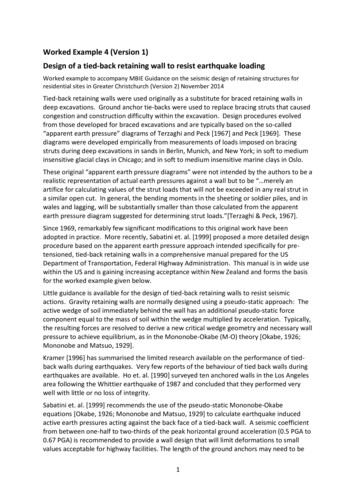
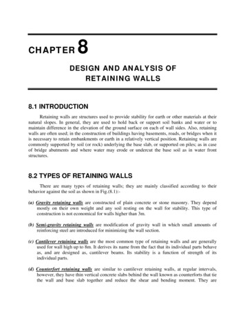
18‐09‐2018Drawing and DetailingOTHER DETAILS Construction joint A key 200 mm wide x 50 mm deep with nominal steel#10@250, 600 mm length in two rowsDrainage: 100 mm dia. pipes as weep holes at 3 m c/c at bottom Also provide 200 mm gravel blanket at the back of thestem for back drain.13
18‐09‐2018THANKS14
DESIGN EXAMPLE -1 RETAINING WALL Dr. Hassan Irtaza, Professor Department of Civil Engg., A.M.U., Aligarh, India Design Example - Cantilever Retaining Wall # Design a cantilever retaining wall (i.e. T-type) to retain earth for a height of 4m. The backfill is horizontal. The density of soil is 18 kN/m3.Safe bearing capacity of soil is 200 kN/m2 .