Transcription
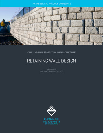
PROFESSIONAL PRACTICE GUIDELINESCIVIL AND TRANSPORTATION INFRASTRUCTURERETAINING WALL DESIGNVERSION 1.1PUBLISHED FEBRUARY 25, 2020
REVISED: VERSION 1.1, FEBRUARY 25, 2020FIRST PUBLISHED: VERSION 1.0, NOVEMBER 19, 2019 2020 ENGINEERS AND GEOSCIENTISTS BRITISH COLUMBIAALL RIGHTS RESERVED.COVER PHOTOGRAPH GARYALVIS/ISTOCK
PREFACEThese Professional Practice Guidelines – RetainingWall Design were developed with the support of theCity of Nanaimo.These guidelines will assist Engineering Professionalsin undertaking the design of Retaining Walls in aconsistent manner, incorporating best practices suchas providing complete documentation, and followingappropriate quality management procedures. Thefocus of these guidelines is on the geotechnicalaspects of Retaining Walls; however, some regulatoryand structural issues are also discussed.These guidelines were written for the information ofEngineering Professionals, statutory decision-makers,regulators, the public, and other stakeholders whomight be involved in, or have an interest in, RetainingWall design in British Columbia (BC).VERSION 1.1These guidelines provide a common level ofexpectation for various stakeholders with respect tothe level of effort, due diligence, and standard ofpractice to be followed when carrying out RetainingWall design and construction in BC.This current revision was undertaken to clarify whenthe assurance statement should be completed, to addfield review requirements to the assurance statement,and to clarify other minor items.These guidelines outline the appropriate standard ofpractice at the time that they were prepared.However, this is a living document that is to berevised and updated, as required, in the future, toreflect the developing state of practice.PROFESSIONAL PRACTICE GUIDELINESRETAINING WALL DESIGNi
VERSION 1.1PROFESSIONAL PRACTICE GUIDELINESRETAINING WALL DESIGNii
TABLE OF CONTENTSPREFACEiABBREVIATIONSvDEFINED TERMSviVERSION HISTORY1.0viiiINTRODUCTION11.1PURPOSE OF THESE GUIDELINES11.2ROLE OF ENGINEERS ANDGEOSCIENTISTS BC2INTRODUCTION OF TERMS21.33.2.1 Requirements of Authorities HavingJurisdiction123.2.2 Canadian Highway Bridge Design Code123.2.3 Ministry of Transportation andInfrastructure123.2.4 Ministry of Forests, Lands, NaturalResources Operations and RuralDevelopment123.2.5 Engineers and Geoscientists BC Guidelines123.2.6 Other Codes and Guidelines123.3RETAINING WALL PERFORMANCEREQUIREMENTS131.3.1 Engineer of Record23.3.1 Performance Expectations131.3.2 Retaining Walls23.3.2 Factor of Safety131.4SCOPE OF THE GUIDELINES61.4.1 Retaining Walls Covered In TheseGuidelines61.4.2 Retaining Walls Not Covered In TheseGuidelines61.5APPLICABILITY OF THE GUIDELINES71.6ACKNOWLEDGEMENTS72.02.12.2ROLES AND RESPONSIBILITIES8COMMON FORMS OF PROJECTORGANIZATION8RESPONSIBILITIES82.2.1 Owner82.2.2 Engineer of Record93.0GUIDELINES FORPROFESSIONAL PRACTICE3.4RETAINING WALL PROJECT APPROACH143.4.1 Initial Assessment143.4.2 Geotechnical Investigation143.4.3 Conceptual Design153.4.4 Detailed Design153.4.5 Field Reviews and Design Changes193.4.6 Assurance Statements193.4.7 Additional Services194.0 QUALITY MANAGEMENT INPROFESSIONAL PRACTICE4.1QUALITY MANAGEMENT REQUIREMENTS20204.1.1 Professional Practice Guidelines204.1.2 Use of Seal204.1.3 Direct Supervision21104.1.4 Retention of Project Documentation21104.1.5 Documented Checks of Engineering Work213.1.1 Design Life103.1.2 Failure104.1.6 Documented Field Reviews DuringImplementation or Construction224.1.7 Documented Independent Review ofStructural Designs233.13.2OVERVIEWREGULATORY REQUIREMENTSVERSION 1.112PROFESSIONAL PRACTICE GUIDELINESRETAINING WALL DESIGNiii
5.0PROFESSIONAL REGISTRATION &EDUCATION, TRAINING, AND EXPERIENCE 245.1PROFESSIONAL REGISTRATION245.2EDUCATION, TRAINING, AND EXPERIENCE246.0 REFERENCES AND RELATED DOCUMENTS256.1REFERENCES256.2RELATED DOCUMENTS277.0APPENDICES29LIST OF APPENDICESAppendix A: Engineer of Record – Retaining Wall Assurance Statement.31Appendix B: Illustrations of Terminology for Retaining Walls. 39LIST OF TABLESTable 1: Types of Retaining Walls. 3Table 2: Characteristics of Typical Retaining Walls . 4Table 3: Retaining Wall Design Guide . 11Table 4: Retaining Wall Design Criteria – Typical Factors of Safety .13LIST OF FIGURESAppendix BFigure B - 1: Retaining Wall Terminology . 41Figure B - 2: Retaining Wall Height Determination . 42Figure B - 3: Retaining Wall Movement Type . 43VERSION 1.1PROFESSIONAL PRACTICE GUIDELINESRETAINING WALL DESIGNiv
ABBREVIATIONSABBREVIATIONTERMBCBritish ColumbiaBCBCBritish Columbia Building CodeCFEMCanadian Foundation Engineering ManualCHBDCCanadian Highway Bridge Design CodeCSACanadian Standards AssociationFHWAFederal Highway AdministrationMFLNRORDMinistry of Forests, Lands, Natural Resource Operations and Rural DevelopmentMoTIMinistry of Transportation and InfrastructureMSEmechanically stabilized earthNBCNational Building Code of CanadaVBBLVancouver Building By-lawVERSION 1.1PROFESSIONAL PRACTICE GUIDELINESRETAINING WALL DESIGNv
DEFINED TERMSThe following definitions are specific to these guidelines. These words and terms are capitalized throughout thedocument. Also see Section 1.3 Introduction of Terms for more information and other terms related toRetaining Walls.TERMDEFINITIONActEngineers and Geoscientists Act [RSBC 1996], Chapter 116.AssociationThe Association of Professional Engineers and Geoscientists of the Province of BritishColumbia, also operating as Engineers and Geoscientists BC.Authority Having JurisdictionThe jurisdictional body (usually municipal) with authority to administer and enforce theBritish Columbia Building Code (BCBC), the City of Vancouver Building By-law (VBBL),the National Building Code of Canada (NBC), or a local building bylaw or code.BylawsThe Bylaws of the Association made under the Act.Cantilever Retaining WallA structure, which is usually either cast-in-place or made of precast concrete but couldinclude reinforced masonry, consisting of a concrete stem and a base (which is typicallya concrete foundation slab), and where both the stem and the base are relatively thinand reinforced to resist the applied moments and shear forces resulting from the lateralearth loading.Engineer of RecordAn Engineering Professional:(a) with the appropriate education, training, and experience to provide professionalservices related to Retaining Wall design and field review, as described in theseguidelines; and(b) who takes overall responsibility for all aspects of the design and field reviews forthe Retaining Wall.Engineering Professional(s)Professional engineers and licensees who are registered or licensed by the Associationand entitled under the Act to engage in the practice of professional engineering inBritish Columbia.Engineers and Geoscientists BCThe business name for the Association.Geoscience Professional(s)Professional geoscientists and licensees who are registered or licensed by theAssociation and entitled under the Act to engage in the practice of professionalgeoscience in British Columbia.Geotechnical MaterialsSoil, rock, mineral ore, and lightweight fill such as pumice or bottom ash.Gravity WallA structure providing lateral support for a mass of soil that owes its stability primarilyto its own weight and to the weight of the soil located directly above its base. Itdepends entirely on the weight of the stone or concrete masonry and of any soil restingon the masonry or concrete foundation slab for its stability, and only a nominal amountof steel is placed near the exposed faces to minimize the risk of surface cracking due totemperature changes.VERSION 1.1PROFESSIONAL PRACTICE GUIDELINESRETAINING WALL DESIGNvi
TERMDEFINITIONMechanically Stabilized EarthWall or MSE WallA soil-retaining system employing either strip or grid-type, metallic, or polymeric tensilereinforcements in the soil mass, and a Wall Facing element that is either vertical ornearly vertical. These walls are sometimes referred to as “structural earth walls” and“retained soil systems.” They typically use a range of proprietary Wall Facing elementsand require soil reinforcement for stability. Also included in this category are greenwalls, in which the Slope Protection supports vegetation growth. For the purpose ofthese guidelines, geosynthetic reinforced soil technology, which uses a geosynthetic asthe reinforcing element in the soil-retaining system, is considered to be a MechanicallyStabilized Earth Wall.Prefabricated Modular WallA soil-retaining system employing interlocking soil-filled timber, synthetic polymer,reinforced or unreinforced concrete, masonry, or steel modules or bins to resist earthpressures by acting as a Gravity Wall.Retaining WallA vertical or near-vertical structure constructed to hold back Geotechnical Materials andsafely deal with any hydrostatic pressure. Retaining Walls can be created outof a variety of structural and Geotechnical Materials. Retaining Walls typically stabilizesoil and rock against downslope movement and provide lateral support for steep tovertical grade changes.Segmental Block Gravity WallA soil-retaining system utilizing manufactured interlocking blocks, usually of concrete,including lock-block walls and proprietary walls such as Allan block walls. A lower wallmay comprise only the blocks retaining soil. A higher wall may use the blocks as WallFacing elements for a Mechanically Stabilized Earth Wall.Semi-Gravity WallSimilar to a Gravity Wall, a structure providing lateral support for a mass of soil thatowes its stability primarily to its own weight and to the weight of the soil locateddirectly above its base. However, a Semi-Gravity Wall is more slender and requiresreinforcement consisting of vertical bars and dowels continuing into the base.Slope ProtectionMaterials placed on the face of a stable slope to minimize the risk of surficial erosion,and sometimes called “revetment.” Slope Protection typically refers to vegetation butcan also include manufactured products such as erosion-control blankets.Stacked Rock WallA soil-retaining system employing interlocking pieces of rock to resist lateral earthpressures by acting as a Gravity Wall. These walls can be constructed with or withoutmortar and with or without geogrid. These are also referred to as rockeries, dry-stacked,or dry-stone walls. If a Stacked Rock Wall is used in conjunction with soilreinforcement, it is considered an MSE Wall.Wall FacingMaterials placed on the face of a stable slope to minimize the risk of surficial erosion,and sometimes called “revetment.” Wall Facing typically refers to rock, concrete paving,or other hard surfacing.VERSION 1.1PROFESSIONAL PRACTICE GUIDELINESRETAINING WALL DESIGNvii
VERSION HISTORYVERSIONNUMBERPUBLISHED DATEDESCRIPTION OF CHANGES1.1February 25, 2020Clarification of when the assurance statement should be completed, inclusion offield review requirements in the assurance statement, and other minorclarifications.1.0November 19, 2019Initial version.VERSION 1.1PROFESSIONAL PRACTICE GUIDELINESRETAINING WALL DESIGNviii
1.0 INTRODUCTIONEngineers and Geoscientists British Columbia (theAssociation) is the regulatory and licensing body forthe engineering and geoscience professions in BritishColumbia (BC). To protect the public, the Associationestablishes, maintains, and enforces standards forthe qualifications and practice of its members andlicensees.The Association provides various practice resources to itsmembers and licensees to assist them in meeting theirprofessional and ethical obligations under the Engineersand Geoscientists Act (the Act). One of those resourcesare professional practice guidelines, which establish thestandard of practice for specific professional activities.The Association works with experts in their fields todevelop professional practice guidelines where additionalguidance is beneficial or required.These Professional Practice Guidelines – RetainingWall Design provide guidance on professional practicefor Engineering Professionals who design RetainingWalls, including on the issues that must be consideredand addressed during Retaining Wall design. Guidanceis also provided on how Engineering Professionalscan meet their obligations regarding qualitymanagement requirements, specifically regardingproject documentation and the need for independentstructural review.This current revision was undertaken to clarify whenthe assurance statement should be completed, to addfield review requirements to the assurance statement,and to clarify other minor items.1.1This document provides guidance to EngineeringProfessionals who carry out a range of professionalactivities related to the design of Retaining Walls in BC.Following are the specific objectives of these guidelines:1.2.3.4.5.6.VERSION 1.1PURPOSE OF THESE GUIDELINESDescribe the standard of practice that EngineeringProfessionals should follow when providingprofessional services related to Retaining Walldesign.Specify the tasks and/or services that EngineeringProfessionals should complete to meet theappropriate standard of practice and fulfill theirprofessional obligations under the Act. Theseobligations include the Engineering Professional’sprimary duty to protect the safety, health, andwelfare of the public and the environment.Describe the roles and responsibilities of thevarious participants/stakeholders involved in theseprofessional activities. The document should assistin delineating the roles and responsibilities of thevarious participants/stakeholders, which mayinclude the Engineer of Record and the owner.Define the skill sets that are consistent with thetraining and experience required to carry out theseprofessional activities.Provide guidance on the use of the assurancestatement (Appendix A: Engineer of Record –Retaining Wall Assurance Statement). The purposeof this assurance statement is to assist EngineeringProfessionals in considering and addressingrelevant regulatory and technical issues.Provide guidance on how to meet the qualitymanagement requirements under the Act andBylaws when carrying out the professionalactivities identified in these professionalpractice guidelines.PROFESSIONAL PRACTICE GUIDELINESRETAINING WALL DESIGN1
1.2ROLE OF ENGINEERS ANDGEOSCIENTISTS BCThese guidelines were prepared by subject matter expertsand reviewed at various stages by a formal review group.The final draft of the guidelines underwent a finalconsultation process with various committees anddivisions of the Association. These guidelines wereapproved by the Association’s Council and, prior topublication, underwent final legal and editorial reviews.These guidelines form part of the Association’s ongoingcommitment to maintaining the quality of professionalservices that Engineering Professionals provide to theirclients and the public.An Engineering Professional must exercise professionaljudgment when providing professional services; as such,application of these guidelines will vary depending on thecircumstances, including where site-specific conditionsneed to be addressed or in the event that there arechanges in legislation or regulations subsequent to thepublication of these guidelines. Where an EngineeringProfessional intends to substantially deviate fromapplying these guidelines, consideration should be madeto obtain a second opinion on the merits of the deviation.The Association supports the principle that appropriatefinancial, professional, and technical resources should beprovided (i.e., by the client and/or the employer) tosupport Engineering Professionals who are responsiblefor carrying out professional activities, so they cancomply with the standard of practice outlined in theseguidelines. These guidelines may be used to assist in thelevel of service and terms of reference of an agreementbetween an Engineering Professional and a client.These guidelines are intended to assist EngineeringProfessionals in fulfilling their professional obligations,especially regarding the first principle of the Association’sCode of Ethics, which is to “hold paramount the safety,health and welfare of the public, protection of theenvironment and promote health and safety in theworkplace.” Failure to meet the intent of these guidelinescould be evidence of unprofessional conduct and lead todisciplinary proceedings by the Association.VERSION 1.11.3INTRODUCTION OF TERMSThe following terms should be noted for theseguidelines. Also see the Defined Terms section at thefront of the document for formal definitions specific tothese guidelines.1.3.1ENGINEER OF RECORDThe Engineer of Record is an Engineering Professionalwith the appropriate education, training, andexperience to provide professional services related toRetaining Wall design and field review, as described inthese guidelines. The Engineer of Record takes overallresponsibility for all aspects of the design and fieldreviews for the Retaining Wall.1.3.2RETAINING WALLSThe following are expanded definitions and additionalterms related to Retaining Walls.1.3.2.1Overview of Retaining WallsA Retaining Wall is a vertical or near-vertical structureconstructed to hold back Geotechnical Materials andsafely deal with any hydrostatic pressure. RetainingWalls can be created out of a variety of structural andGeotechnical Materials. Geotechnical Materials includesoil, rock, mineral ore, and lightweight fill such aspumice or bottom ash. Retaining Walls typically stabilizesoil and rock against downslope movement and providelateral support for steep to vertical grade changes.A reinforced slope is a constructed earth slope (aninclined surface, either natural or constructed)containing reinforcing elements (for example, geogrid)within the soil mass and Slope Protection and/or WallFacing to provide erosion protection. A reinforced slopesteeper than 45 (1H:1V) should be treated as aRetaining Wall, for the purposes of these guidelines.Slope Protection and Wall Facing are materials placedon the face of a stable slope to minimize the risk ofsurficial erosion, sometimes called “revetment.” SlopeProtection typically refers to vegetation but can alsoinclude manufactured products such as erosion-controlPROFESSIONAL PRACTICE GUIDELINESRETAINING WALL DESIGN2
blankets. Wall Facing typically refers to rock, concretepaving, or other hard surfacing. Slope Protection andWall Facing are not considered Retaining Walls if slopestability analysis shows the slope is stable with andwithout the Slope Protection and Wall Facing.A Retaining Wall is considered critical to the stability ofa building foundation when any part of it lies within thezone of influence of the foundation, typically defined asbeing below a 1H:1V plane extending downwards fromthe outside of a building footing. The zone of influenceshould be confirmed with stability analysis forfoundations within or near the 1H:1V plane or for soilconditions that merit it (for example, fissured clay). Ifthe 1H:1V plane is encroached by a temporary slopeexcavated to facilitate Retaining Wall construction, thestability of this temporary slope, including theinfluence of building loads, should be assessed.1.3.2.2Types of Retaining WallsTable 1: Types of Retaining Walls below describes thetypes of Retaining Walls for the purposes of theseguidelines.1.3.2.3Characteristics of Typical Retaining WallsFigures B-1, B-2, and B-3 in Appendix B: Illustrations ofTerminology for Retaining Walls depict variouscharacteristics of typical Retaining Walls, as discussedin these guidelines.Table 2: Characteristics of Typical Retaining Wallsbelow provides more detailed explanations of thesecharacteristics and other terminology.Table 1: Types of Retaining WallsTYPE OF WALLDESCRIPTIONCantilever RetainingWallA structure, which is usually either cast-in-place or made of precast concrete but could includereinforced masonry, consisting of a concrete stem and a base (which is typically a concrete foundationslab), and where both the stem and the base are relatively thin and reinforced to resist the appliedmoments and shear forces resulting from the lateral earth loading.Gravity WallA structure providing lateral support for a mass of soil that owes its stability primarily to its ownweight and to the weight of the soil located directly above its base. It depends entirely on the weightof the stone or concrete masonry and of any soil resting on the masonry or concrete foundation slabfor its stability, and only a nominal amount of steel is placed near the exposed faces to minimize therisk of surface cracking due to temperature changes.MechanicallyStabilized Earth Wallor MSE WallA soil-retaining system employing either strip or grid-type, metallic, or polymeric tensilereinforcements in the soil mass, and a Wall Facing element that is either vertical or nearly vertical.These walls are sometimes referred to as “structural earth walls” and “retained soil systems.” Theytypically use a range of proprietary Wall Facing elements and require soil reinforcement for stability.Also included in this category are green walls, in which the Slope Protection supports vegetationgrowth. For the purpose of these guidelines, geosynthetic reinforced soil technology, which uses ageosynthetic as the reinforcing element in the soil-retaining system, is considered to be aMechanically Stabilized Earth Wall.PrefabricatedModular WallA soil-retaining system employing interlocking soil-filled timber, synthetic polymer, reinforced orunreinforced concrete, masonry, or steel modules or bins to resist earth pressures by acting as aGravity Wall.VERSION 1.1PROFESSIONAL PRACTICE GUIDELINESRETAINING WALL DESIGN3
TYPE OF WALLDESCRIPTIONSegmental BlockGravity WallA soil-retaining system utilizing manufactured interlocking blocks, usually of concrete, includinglock-block walls and proprietary walls such as Allan block walls. A lower wall may comprise only theblocks retaining soil. A higher wall may use the blocks as Wall Facing element for a MechanicallyStabilized Earth Wall.Semi-Gravity WallSimilar to a Gravity Wall, a structure providing lateral support for a mass of soil that owes its stabilityprimarily to its own weight and to the weight of the soil located directly above its base. However, aSemi-Gravity Wall is more slender and requires reinforcement consisting of vertical bars and dowelscontinuing into the base.Stacked Rock WallA soil-retaining system employing interlocking pieces of rock to resist lateral earth pressures by actingas a Gravity Wall. These walls can be constructed with or without mortar and with or without geogrid.These are also referred to as rockeries, dry-stacked, or dry-stone walls. If a Stacked Rock Wall is usedin conjunction with soil reinforcement, it is considered an MSE Wall.Table 2: Characteristics of Typical Retaining WallsCHARACTERISTICDESCRIPTIONbackslopeAverage ground inclination measured from the top of the Retaining Wall to the crest of the slope ofretained soil (see Figure B - 1a).blanket drain orchimney drainA vertical drain located directly against the back of a Retaining Wall (as shown in Figure B - 1a), or aninclined or horizontal drain on the surface of a cut slope or toe area, as shown in see Figure B - 1b,where seepage is occurring or may occur, to reduce water flow into the Retaining Wall backfill zone.A blanket drain provides full coverage along the length of the wall while a chimney drain providesintermittent coverage.broken backslopeBackslope that reduces to a flatter/horizontal grade (see Figure B - 1b).drainage systemAn engineered system consisting of a permeable medium, hydraulically connected to subsurface pipesor weep holes through the Retaining Wall or beyond the end(s) of the wall, which collects, conveys, anddischarges water; intended to reduce hydrostatic pressures and minimize the risk of erosion.embedment depthDepth from finished grade level in front of the Retaining Wall to the base of the wall footing; theminimum embedment depth is typically greater than the frost considerations and may also providestability (see Figure B - 1a and Figure B - 1b).external stabilityStability of the Retaining Wall relating to rotation (overturning), sliding (translation), and bearingcapacity failure modes. (see Figure B - 3a and Figure B - 3b for rotation and sliding)GeotechnicalMaterials aSoil, rock, mineral ore, and lightweight fill such as pumice or bottom ash.global stabilityStability against deep-seated failure that encompasses a Retaining Wall, or, in the case of terracedRetaining Walls, one or more of the individual walls.internal stabilityStability against failure of materials comprising the Retaining Wall (for example, reinforced concrete inthe case of cast-in-place Cantilever Retaining Walls, soil reinforcing in the case of MechanicallyStabilized Earth Walls).reinforced fill zoneThe composite backfill and reinforcement zone in a Mechanically Stabilized Earth Wall.VERSION 1.1PROFESSIONAL PRACTICE GUIDELINESRETAINING WALL DESIGN4
CHARACTERISTICDESCRIPTIONrestrained(non-yielding) wallsRetaining Walls that are prevented from moving sufficiently to develop active pressures behind thewall.retained soilFill (typically compacted mineral soil) immediately behind Gravity Walls or cast-in-place CantileverRetaining Walls, and the backfill behind the reinforced fill zone in Mechanically Stabilized Earth Walls,as well as the in-situ Geotechnical Materials that require the Retaining Wall for stability.Slope Protection aMaterials placed on the face of a stable slope to minimize the risk of surficial erosion, and sometimescalled “revetment.” Slope Protection typically refers to vegetation but can also include manufacturedproducts such as erosion-control blankets.toe slopeAverage ground inclination measured from the exposed bottom of the wall to the toe of the slope infront of the wall.unrestrained(yielding) wallsRetaining Walls that are able to move sufficiently to allow active pressures to develop behind the wallin the limiting condition.wall batterSlope of the front and/or back face of a Retaining Wall. Negative wall batter is when the top of the frontface overhangs the bottom of the exposed wall.wall heightDistance from the bottom of the exposed wall to the top of the Retaining Wall (see Figure B - 2a). Wherethe backslope above the wall or a toe slope below the wall is steeper than 2H:1V, the wall height shouldinclude the height of that slope (see Figure B - 2b). The wall height does not include the height of aparapet or guard where one is utilized.wall movementRotational and/or sliding movement (as shown in Figure B - 3a and Figure B - 3b). Rotational movementresults in an increase or decrease in the wall batter, whereas sliding movement does not significantlyimpact the wall batter.Wall FacingaMaterials placed on the face of a stable slope to minimize the risk of surficial erosion, and sometimescalled “revetment.” Wall Facing typically refers to rock, concrete paving, or other hard surfacing.NOTEa These terms are capitalized because they are formally defined terms. See the list of Defined Terms at the beginning of theseguidelines.VERSION 1.1PROFESSIONAL PRACTICE GUIDELINESRETAINING WALL DESIGN5
1.4SCOPE OF THE GUIDELINESThese guidelines apply to the types of Retaining Wallsdiscussed in Section 1.4.1 Retaining Walls Covered InThese Guidelines below. The focus of these guidelinesis on the geotechnical aspects of Retaining Wall design;however, some regulatory and structural issues arealso discussed.These guidelines are not intended to be prescriptive,nor are they intended to serve as a substitute forengineering judgement and experience. TheAssociation recognizes that professionals andcontractors may pursue innovative Retaining Walldesign and construction. In such instances, it must bedemonstrated that the proposed Retaining Wall willmeet or exceed safety and performance expectationsas outlined in these guidelines.requirements of the BCBC or VBBL, and the guidance asprovided in these guidelines.For terraced Retaining Walls other than those describedin Section 1.4.2 Retaining Walls Not Covered In TheseGuidelines, the design aspects covered in theseguidelines should be considered for each wall, bothindividually and in combination.1.4.2These guidelines do not apply to the followingRetaining Wall types: Retaining Walls less than 1.2 m high, unless failurewould impact a structure or impact life safety. Terraced Retaining Walls less than 1.2 m high,with: Where wall types are not specifically covered inthese guidelines, Engineering Professionals shouldrefer to the Association’s professional practiceguidelines entitled Guidelines for GeotechnicalEngineering Services for Building Projects (Engineersand Geoscientists BC 1998) and Guidelines for Legislated Landslide Assessments for ProposedResidential Developments in BC (Engineers andGeoscientists BC 2010), and should use their ownprofessional judgment.1.4.1RETAINING WALLS COVERED IN THESEGUIDELINES Cantilever Retaining WallGravity Wall and Semi-Gravity WallSegmental Block Gravity WallMechanically Stabilized Earth Wall (MSE W
viii 1.0 INTRODUCTION 1 1.1 PURPOSE OF THESE GUIDELINES 1 1.2 ROLE OF ENGINEERS AND GEOSCIENTISTS BC 2 1.3 INTRODUCTION OF TERMS 2 1.3.1 Engineer of Record 2 1.3.2 Retaining Walls 2 1.4 SCOPE OF THE GUIDELINES 6 1.4.1 Retaining Walls Covered In These Guidelines 6 1.4.2 Retaining Walls