Transcription
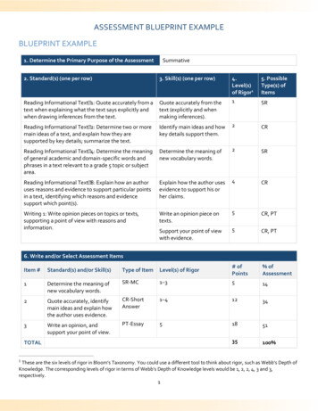
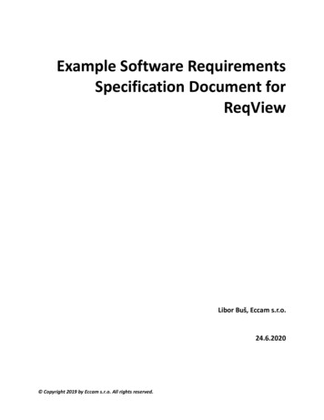
Retaining wallsExample 3.16 Design of a cantilever retaining wall (BS 8110)The cantilever retaining wall shown below is backfilled with granular material having a unit weight, ρ, of 19 kNm 3and an internal angle of friction, φ, of 30 . Assuming that the allowable bearing pressure of the soil is 120 kNm 2, thecoefficient of friction is 0.4 and the unit weight of reinforced concrete is 24 kNm 31. Determine the factors of safety against sliding and overturning.2. Calculate ground bearing pressures.3. Design the wall and base reinforcement assuming fcu 35 kNm 2, fy 500 kNm 2 and the cover to reinforcementin the wall and base are, respectively, 35 mm and 50 mm.ka 5000FAWWWs1 sin φ1 sin φ 1 sin 30 1 sin 30 1 0.5 1 1 0.5 3400AWb700 4002900Activepressure ( p a) k aρh 1/3 19 5.4 34.2 kN m 2SLIDINGConsider the forces acting on a 1 m length of wall. Horizontal force on wall due to backfill, FA, isFA 0.5pah 0.5 34.2 5.4 92.34 kNandWeight of wall (Ww) 0.4 5 24 48.0 kNWeight of base (Wb) 0.4 4 24 38.4 kNWeight of soil (Ws) 2.9 5 19 275.5 kNTotal vertical force (Wt) 361.9 kNFriction force, FF, isFF µWt 0.4 361.9 144.76 kNAssume passive pressure force (FP) 0. Hence factor of safety against sliding is144.76 1.56 1.5 OK92.34OVERTURNINGTaking moments about point A (see above), sum of overturning moments (Mover) isFA 5.4 92.34 5.4 166.2 kNm331259780415467193 C03b1259/3/09, 1:14 PM
Design of reinforced concrete elements to BS 8110Example 3.16 continuedSum of restoring moments (Mres ) isMres Ww 0.9 Wb 2 Ws 2.55 48 0.9 38.4 2 275.5 2.55 822.5 kNmFactor of safety against overturning is822.5 4.9 2.0 OK166.2GROUND BEARING PRESSUREMoment about centre line of base (M) isM FA 5.4 WW 1.1 WS 0.55392.34 5.4 48 1.1 275.5 0.55 67.5 kNm3N 361.9 kNM67.5D4 0.187 m 0.666 mN361.96 6Therefore, the maximum ground pressure occurs at the toe, ptoe, which is given byptoe 361.9 6 67.5 116 kNm 2 allowable (120 kNm 2)442Ground bearing pressure at the heel, pheel, ispheel 361.9 6 67.5 65 kNm 2 442BENDING REINFORCEMENTWallHeight of stem of wall, hs 5 m. Horizontal force on stem due to backfill, Fs, isFs 0.5kaρh s2 0.5 1/3 19 52 79.17 kNm 1 widthDesign moment at base of wall, M, isM γ fFsh s 1.4 79.17 5 184.7 kNm33Effective depthAssume diameter of main steel (Φ) 20 mm.Hence effective depth, d, isd 400 cover Φ/2 400 35 20/2 355 mmUltimate moment of resistanceMu 0.156fcubd 2 0.156 35 103 3552 10 6 688 kNmSince Mu M, no compression reinforcement is required.1269780415467193 C03b1269/3/09, 1:14 PM
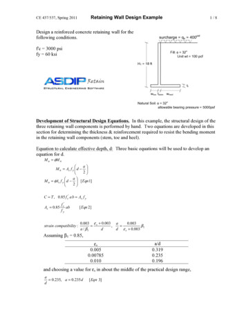
Retaining wallsExample 3.16 continuedSteel areaK M184.7 106 0.0419fcubd 2 35 103 3552z d [0.5 ( 0.25 K /0.9)] 355 [0.5 ( 0.25 0.0419/0.9)] 337 mmMAs 184.7 106 1260 mm2 /m0.87f y z0.87 500 337Hence from Table 3.22, provide H20 at 200 mm centres (A s 1570 mm2/m) in near face (NF) of wall. Steel is alsorequired in the front face (FF) of wall in order to prevent excessive cracking. This is based on the minimum steelarea, i.e. 0.13%bh 0.13% 103 400 520 mm2/mHence, provide H12 at 200 centres (A s 566 mm2)BaseHeel275.5 1.4 385.7 kN700 400ToeA B2900Cp1DHeelp 2 1.4 65 91 kN m 2p3p 1 1.4 116 162.4 kN m 2p3 91 2.9(162.4 91) 142.8 kNm 24Design moment at point C, Mc, is385.7 2.9 2.9 38.4 1.4 1.45 91 2.9 2 51.8 2.9 2.9 160.5 kNm 2422 3Assuming diameter of main steel (Φ) 20 mm and cover to reinforcement is 50 mm, effective depth, d, isd 400 50 20/2 340 mmK 160.5 106 0.039735 103 340 2z 340 [0.5 (0.25 0.0397/0.9)] 0.95d 323 mmAs M 160.5 106 1142 mm2 /m0.87f y z0.87 500 323Hence from Table 3.22, provide H20 at 200 mm centres (A s 1570 mm2/m) in top face (T) of base.1279780415467193 C03b1279/3/09, 1:14 PM
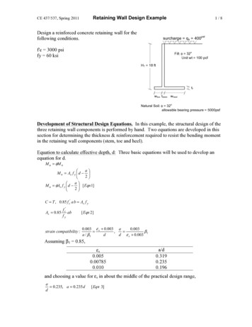
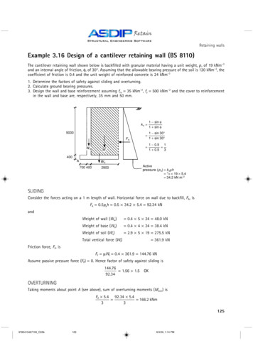
Design of reinforced concrete elements to BS 8110Example 3.16 continuedToeDesign moment at point B, MB, is given byMB 162.4 0.7 2 0.7 38.4 1.4 0.7 36.5 kNm24 2As 36.5 1142 260 mm2/m minimum steel area 520 mm2/m160.5Hence provide H12 at 200 mm centres (A s 566 mm2/m), in bottom face (B) of base and as distribution steel in baseand stem of wall.REINFORCEMENT DETAILSThe sketch below shows the main reinforcement requirements for the retaining wall. For reasons of buildability theactual reinforcement details may well be slightly different.U-bars H12-200(FF) far face(NF) near face(T) top face(B) bottom faceH12-200(FF)Distributionsteel H12-200200 kickerH20-200 (NF)Starter bars H20-200H20-200 (T)DistributionsteelH12-2003.13 Design of short bracedcolumnsThe function of columns in a structure is to act asvertical supports to suspended members such asbeams and roofs and to transmit the loads fromthese members down to the foundations (Fig. 3.83).Columns are primarily compression membersalthough they may also have to resist bendingmoments transmitted by beams.H12-200 (B)Columns may be classified as short or slender,braced or unbraced, depending on various dimensional and structural factors which will be discussedbelow. However, due to limitations of space, thestudy will be restricted to the design of the mostcommon type of column found in building structures, namely short-braced columns.3.13.1 COLUMN SECTIONSSome common column cross-sections are shownin Fig. 3.84. Any section can be used, however,1289780415467193 C03b1289/3/09, 1:14 PM
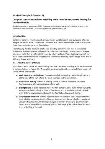
Project: Verification ExampleEngineer: Javier Encinas, PEDescrip: Cantilever Retaining Wall - MetricASDIP Retain 3.0.0CANTILEVER RETAINING WALL DESIGNGEOMETRYConc. Stem Height .Stem Thickness Top .Stem Thickness Bot .Footing Thickness .Toe Length .Heel Length .Soil Cover @ Toe .Backfill Height .Backfill Slope Angle .5.0040.040.040.00.702.900.005.000.0SEISMIC EARTH FORCESHor. Seismic Coeff. kh .0.00Ver. Seismic Coeff kv .0.00Seismic Active Coeff. Kae0.30Seismic Force Pae-Pa .-8.8mcmcmmmmmm OKdegKN/mSOIL BEARING PRESSURESAllow. Bearing Pressure .120.0 KPaMax. Pressure @ Toe . 115.0 KPaMin. Pressure @ Heel .65.1 KPaTotal Footing Length .4.00 mFooting Length / 6 .0.67 mResultant Eccentricity e .0.18 mResultant is Within the Middle ThirdOKPage #6/29/2014www.asdipsoft.comAPPLIED LOADSUniform Surcharge .0.0 KPaStrip Pressure .0.0 KPaStrip 0.6 m deep, 1.2 m wide @ 0.9 m from StemStem Vertical (Dead) .0.0 KN/mStem Vertical (Live) .0.0 KN/mVertical Load Eccentricity15.2 cmWind Load on Stem .0.0 KPaBACKFILL PROPERTIESBackfill Density .19.0 KN/m³Earth Pressure Theory .Rankine ActiveInternal Friction Angle .30.0 degActive Pressure Coeff. Ka0.336.3 KPa/mActive Pressure @ Wall .Active Force @ Wall Pa .92.3 KN/mWater Table Height .0.00 mSHEAR KEY DESIGNShear Key Depth .0.0Shear Key Thickness .0.00.0Max. Shear Force @ Key .0.00Shear Capacity Ratio .No shear key has been specified0.00Moment Capacity Ratio .cmcmKN/mOKOK1
Project: Verification ExampleEngineer: Javier Encinas, PEDescrip: Cantilever Retaining Wall - MetricASDIP Retain 3.0.0CANTILEVER RETAINING WALL DESIGNPage #6/29/2014www.asdipsoft.comOVERTURNING CALCULATIONS (Comb. D H W)OVERTURNINGRESISTINGForce Arm MomentForce Arm MomentKN/mmKN-m/mKN/mmKN-m/mBackfill Pa . 92.341.80166.2Stem Top . 47.120.9042.4Water Table .0.000.130.0Stem Taper .0.001.100.0Surcharge Hor .0.002.700.0CMU Stem at Top .0.000.000.0Strip Load Hor .0.002.500.0Footing Weight . 37.702.0075.4Wind Load .0.004.640.0Shear Key .0.000.700.0Seismic Pae-Pa .0.003.240.0Soil Cover @ Toe .0.000.350.0Seismic Water .0.000.130.0Stem Wedge .0.001.100.0Seismic Selfweight0.000.000.0Backfill Weight . 275.502.55702.5Rh 92.34OTM 166.2Backfill Slope .0.003.030.0Water Weight .0.002.550.0166.2SeismicPae-Pa.0.004.000.0Arm of Horizontal Resultant 1.80 m92.34Pa Vert @ Heel .0.004.000.0820.3Arm of Vertical Resultant 2.28 mVertical Load .0.000.950.0360.32Surcharge Ver .0.002.550.0Overturning Safety Factor 820.3 4.94 2Strip Load Ver .0.002.550.0166.2OKRv 360.32RM 820.3STEM DESIGN (Comb. 0.9D 1.6H E)HeightdMuϕMnRatiomcmKN-m/m 3.9241.60.640.0035.5211.1241.60.87 OKShear Force @ Crit. Height . 117.7 KN/m OKResisting Shear ϕVc . 261.5 KN/mUse vertical bars D20 @ 20 cm at backfill sideCut off alternate bars. Cut off length 2.13 mVert. Bars Embed. Ldh Reqd . 28.4 cmOKVert. Bars Splice Length Ld . 54.6 cmSLIDING CALCS (Comb. D H W)Footing-Soil Friction Coeff. .0.40Friction Force at Base . 144.1 KN/m3.00Passive Pressure Coeff. Kp .Depth to Neglect Passive .0.40 mPassive Pressure @ Wall . Infinity KPa/mPassive Force @ Wall Pp .0.0 KN/mHoriz. Resisting Force . 144.1 KN/m92.3 KN/mHoriz. Sliding Force .144.1Sliding Safety Factor 1.56 1.5 OK92.31234LOAD COMBINATIONS (ASCE 7)STABILITYSTRENGTHD H W1 1.4DD L H W2 1.2D 1.6(L H)D H 0.7E3 1.2D 0.8WD L H 0.7E4 1.2D L 1.6W5 1.2D L E6 0.9D 1.6H 1.6W27 0.9D 1.6H E
Project: Verification ExampleEngineer: Javier Encinas, PEDescrip: Cantilever Retaining Wall - MetricASDIP Retain 3.0.0CANTILEVER RETAINING WALL DESIGNHEEL DESIGN (Comb. 0.9D 1.6H E)Force Arm MomentKN/mmKN-m/mUpward Pressure . -182.41.08197.3Concrete Weight .24.61.4535.7Backfill Weight .248.01.45359.5Backfill Slope .0.01.930.0Water Weight .0.01.450.0Surcharge Ver. .0.01.450.0Strip Load Ver. .0.01.450.090.1Mu 197.993.7 KN/m OKShear Force @ Crit. Sect. .Resisting Shear ϕVc . 249.7 KN/mUse top bars D20 @ 20 cm , Transv. D12 @ 20 cmResisting Moment ϕMn . 230.3 KN-m/m OKDevelop. Length Ratio at End .0.19OK0.52OKDevelop. Length Ratio at Toe .Page #6/29/2014www.asdipsoft.comTOE DESIGN (Comb. 1.2D 1.6(L H))Force Arm MomentKN/mmKN-m/mUpward Presssure107.40.3638.4Concrete Weight .-7.90.35-2.8Soil Cover .0.00.350.099.4Mu 35.650.6 KN/m OKShear Force @ Crit. Sect. .253.4 KN/mResisting Shear ϕVc .Use bott. bars D12 @ 20 cm , Transv. D12 @ 20 cmResisting Moment ϕMn .86.2 KN-m/m OKDevelop. Length Ratio at End .0.19OK0.04OKDevelop. Length Ratio at Stem .MATERIALSStem FootingConcrete f'c .35.035.0Rebars fy .500.0500.0MPaMPa3
Project: Verification ExampleEngineer: Javier Encinas, PEDescrip: Cantilever Retaining Wall - MetricASDIP Retain 3.0.0CANTILEVER RETAINING WALL DESIGNDESIGN CODESGeneral Analysis .Concrete Design .Masonry Design .Load Combinations .Page #6/29/2014www.asdipsoft.comIBC-12ACI 318-11MSJC-11ASCE 7-054
Project: Verification ExampleEngineer: Javier Encinas, PEDescrip: Cantilever Retaining Wall - MetricCANTILEVER RETAINING WALL DESIGNASDIP Retain 3.0.0Page #6/29/2014www.asdipsoft.comConc. Stem Height .mUniform Surcharge .KPaStem Thickness Top .cmStrip Pressure .KPaStem Thickness Bot .cmFooting Thickness .mStem Vertical (Dead) .KN/mToe Length .mStem Vertical (Live) .KN/mHeel Length .mVertical Load Eccentricity .cmSoil Cover @ Toe .mWind Load on Stem .KPaBackfill Height .mWind Height from Top .mBackfill Slope Angle .degWall taperOKaTan ((40.0 - 40.0) / 100 / 5.00) 0.000 radBackfill slope0.0 * 3.14 / 180 0.000 radInternal frictionWall-soil friction30.0 * 3.14 / 180 0.524 rad0.524 / 2 0.262 radSeismic angleaTan (0 / (1 - 0)) 0.000 radFooting length0.70 40.0 / 100 2.90 4.00 mHeight for Stability0.00 5.00 40.0 / 100 5.40 mEarth pressure theory Rankine ActiveMoist density 19 KN/m³Active coefficientActive pressureSaturated density 20 KN/m³ 0.330.33 * 19.0 6.3 KPa/m of height- For stability analysis (non-seismic)Active force0.33 * 19.0 * 5.40² / 2 92.3 KN/m92.3 * Cos (0.000) 92.3 KN/m ,92.3 * Sin (0.000) 0.0 KN/mWater forcePw (0.33 * (20.4 - 9.8 - 19.0) 9.8) * (0.00 40.0 / 100)² / 2 0.0 KN/m- For stem design (non-seismic)Active force0.33 * 19.0 * 5.00² / 2 79.2 KN/m79.2 * Cos (0.000) 79.2 KN/m ,79.2 * Sin (0.000) 0.0 KN/mWater forcePw (0.33 * (20.4 - 9.8 - 19.0) 9.8) * 0.00² / 2 0.0 KN/m1
Project: Verification ExampleEngineer: Javier Encinas, PEDescrip: Cantilever Retaining Wall - MetricPage #6/29/2014CANTILEVER RETAINING WALL DESIGNASDIP Retain 3.0.0Active seismic coeff.www.asdipsoft.com 0.30- For stability analysis (seismic)Seismic force0.30 * 19.0 * 5.40² / 2 * (1 - 0.0 ) 83.5 KN/m83.5 * Cos (0.262 0.000) 80.7 KN/m83.5 * Sin (0.262 0.000) 21.6 KN/mWater forcePwe 0.00 * (20.4 - 19.0) * (0.00 40.0 / 100)² / 2 0.0 KN/m- For stem design (seismic)Seismic force0.30 * 19.0 * 5.00² / 2 71.6 KN/m71.6 * Cos (0.262 0.000) 69.1 KN/m71.6 * Sin (0.262 0.000) 18.5 KN/mWater forcePwe 0.00 * (20.4 - 19.0) * 0.00² / 2 0.0 KN/mBackfill Arm 1.0 * 92.3 92.3 KN/m5.40 / 3 1.80 mMoment 92.3 * 1.80 166.2 KN-m/mWater table 1.0 * 0.0 0.0 KN/mArm (0.00 40.0 / 100) / 3 0.13 mSurcharge Arm Moment 0.0 * 0.13 0.0 KN-m/m1.0 * 0.33 * 0.0 * 5.40 0.0 KN/m5.40 / 2 2.70 mMoment 0.0 * 2.70 0.0 KN-m/mStrip load 0.0 KN/mArm 2.50 mMoment 0.0 * 2.50 0.0 KN-m/mWind load 1.0 * 0.0 * 1.52 0.0 KN/mArm 40.0 / 100 5.00 - 1.52 / 2 4.64 mMoment 0.0 * 4.64 0.0 KN-m/m0.0 * (
Example 3.16 Design of a cantilever retaining wall (BS 8 110) The cantilever retaining wall shown below is backÞlled with granular material having a unit weight, , of 19 kNm 3 and an internal angle of friction, , of 30 . Assuming that the allowable bearing pressure of the soil is 120 kNm 2, the coefÞcient of friction is 0.4 and the unit weight of reinforced concrete is 24 kNm 3 1. Determine the factors of safety against