Transcription
Worked Example 4 (Version 1)Design of a tied-back retaining wall to resist earthquake loadingWorked example to accompany MBIE Guidance on the seismic design of retaining structures forresidential sites in Greater Christchurch (Version 2) November 2014Tied-back retaining walls were used originally as a substitute for braced retaining walls indeep excavations. Ground anchor tie-backs were used to replace bracing struts that causedcongestion and construction difficulty within the excavation. Design procedures evolvedfrom those developed for braced excavations and are typically based on the so-called“apparent earth pressure” diagrams of Terzaghi and Peck [1967] and Peck [1969]. Thesediagrams were developed empirically from measurements of loads imposed on bracingstruts during deep excavations in sands in Berlin, Munich, and New York; in soft to mediuminsensitive glacial clays in Chicago; and in soft to medium insensitive marine clays in Oslo.These original “apparent earth pressure diagrams” were not intended by the authors to be arealistic representation of actual earth pressures against a wall but to be “ merely anartifice for calculating values of the strut loads that will not be exceeded in any real strut ina similar open cut. In general, the bending moments in the sheeting or soldier piles, and inwales and lagging, will be substantially smaller than those calculated from the apparentearth pressure diagram suggested for determining strut loads.”[Terzaghi & Peck, 1967].Since 1969, remarkably few significant modifications to this original work have beenadopted in practice. More recently, Sabatini et. al. [1999] proposed a more detailed designprocedure based on the apparent earth pressure approach intended specifically for pretensioned, tied-back retaining walls in a comprehensive manual prepared for the USDepartment of Transportation, Federal Highway Administration. This manual is in wide usewithin the US and is gaining increasing acceptance within New Zealand and forms the basisfor the worked example given below.Little guidance is available for the design of tied-back retaining walls to resist seismicactions. Gravity retaining walls are normally designed using a pseudo-static approach: Theactive wedge of soil immediately behind the wall has an additional pseudo-static forcecomponent equal to the mass of soil within the wedge multiplied by acceleration. Typically,the resulting forces are resolved to derive a new critical wedge geometry and necessary wallpressure to achieve equilibrium, as in the Mononobe-Okabe (M-O) theory [Okabe, 1926;Mononobe and Matsuo, 1929].Kramer [1996] has summarised the limited research available on the performance of tiedback walls during earthquakes. Very few reports of the behaviour of tied back walls duringearthquakes are available. Ho et. al. [1990] surveyed ten anchored walls in the Los Angelesarea following the Whittier earthquake of 1987 and concluded that they performed verywell with little or no loss of integrity.Sabatini et. al. [1999] recommends the use of the pseudo-static Mononobe-Okabeequations [Okabe, 1926; Mononobe and Matsuo, 1929] to calculate earthquake inducedactive earth pressures acting against the back face of a tied-back wall. A seismic coefficientfrom between one-half to two-thirds of the peak horizontal ground acceleration (0.5 PGA to0.67 PGA) is recommended to provide a wall design that will limit deformations to smallvalues acceptable for highway facilities. The length of the ground anchors may need to be1
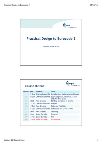
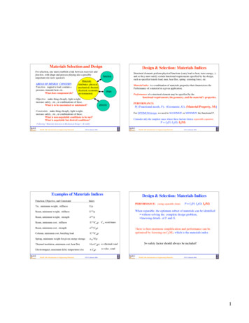
increased beyond that calculated for static design with the anchor bond zone locatedoutside of the Mononobe-Okabe active wedge of soil.McManus [2008] provides a detailed design procedure for earthquake resistant design oftied-back retaining walls based on the recommendations of Sabatini et.al. Numericalanalyses of several case studies showed that all of the walls designed using the procedurewere robust and would be expected to perform very well, including those designed only toresist gravity loads. In some cases large permanent deformations were calculated (up to400 mm) but these were for very large earthquakes (scaled peak ground acceleration of 0.6g). In all cases the walls remained stable with anchor forces safely below ultimate tensilestrength. Wall bending moments reached yield in some cases for the extreme earthquakes,but this is considered acceptable provided the wall elements are detailed for ductility.Walls designed to resist low levels of horizontal acceleration (0.1 g and 0.2 g) showedsignificant improvements in performance over gravity only designs in terms of permanentdisplacement for relatively modest increases in cost. Walls designed to resist higher levelsof horizontal acceleration (0.3 g and 0.4 g) showed additional improvements in performancebut at much greater increases in cost.The worked example given below uses the detailed procedure of Sabatini et. al [1999]“FHWA procedure” with modifications by McManus [2008] for the earthquake loading case.Increasingly, practitioners are relying on computer “black box” software to design tied-backwalls with methodologies that range from fully elastic “beam-on-elastic-foundation”approaches to limiting equilibrium approaches. Caution is required when using “black box”software to ensure that all possible failure modes have been considered.1.1Possible modes of failurePossible modes of failure for tied-back retaining walls are illustrated in cartoon fashion inFigure X.1. A complete design needs to address each of these modes of failurea) Tensile failure of tendon: The range of tendon loads must be established withsuitable margins for safety.b) Grout/ground bond failure: Generally this should always be established on site byproof testing given the difficulty in predicting the capacity and the dependence oninstaller skill and technique.c) Tendon/grout bond failure: Prevented by reference to proven, commercial anchordetails.d) Wall bending failure: Actual wall bending moments are very difficult to predictbecause of the interaction between soil and structure stiffness and the non-linearityof soil stiffness. However, wall hinging does not necessarily create a mechanismprovided the wall element is ductile.e) Passive failure at foot of wall: Insufficient embedment depth for poles leads topassive failure of the soil immediately in front of the wall and instability of the walland soil mass.f) Forward rotation of wall: Staging of excavation is necessary to prevent forwardrotation of wall prior to anchor installation. Wall needs sufficient bending strength2
to resist cantilever moments for staged excavation. Anchors need to be of sufficientcapacity and length to prevent forward rotation.g) Bearing failure underneath wall: Caused by downwards component of anchorforce. Check axial capacity of soldier piles, or, bearing capacity of foot of continuouswall. Bearing loads may be reduced by reducing the anchor inclination (15 degrees isa practical minimum).h) Failure by overturning: Essentially same as (f). Anchors need to be of sufficientcapacity and length to prevent forward rotation.i) Failure by sliding: Possible mode for cohesionless soils. Factor of safety controlledby increasing depth of embedment of wall and/or poles. Factor of safety calculatedusing limiting equilibrium “wedge” analysis.j) Failure by rotation: Possible mode for cohesive soils. Factor of safety controlled byincreasing depth of embedment of wall and/or soldier piles. Factor of safetycalculated using limiting equilibrium “Bishop” analysis or similar.3
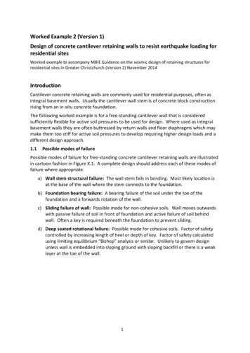
Figure X.1. Possible modes of failure for tied-back retaining walls[Source: Sabatini et. al., 1999].The following procedure addresses each of the above failure modes and is intended to bereadily calculated by hand, although use of calculation software such as Mathcad or Excelwill be useful for design iterations. The example calculations are made here using Mathcad.1.2Example WallThe example wall is shown in Figure X.2 and consists of a 4 m high timber pole wall withground anchor tie-backs. The wall is assumed to be protecting a levelled dwelling platformwith a steep, 20 degree hill slope above. The wall is assumed to be located in theChristchurch Port Hills.The following design assumptions were made:Soil type:Port Hills loessStrength parameters:c 0, φ 30 degrees(Drained strength parameters for Port Hills loess were assumed as recommended elsewherein the Guidelines)Wall situation:Case 4: Retaining wall protecting dwelling up-slopeSeismic parameters:𝐶(𝑇) 𝐶ℎ (𝑇)𝑍𝑍𝑍(𝑇, 𝐷)Ch(T)Equation (1.1) from Guidelines1.33 for Class C assuming shallow soil siteZ 0.3 for Christchurch for ULS4
R Return period factor 1.0 for Importance Level 2 walls, ULSN(T,D) Near fault factor which may be taken 1.0 for residential retaining wallsC(T) 0.3 x 1.33 0.4C(T,Atopo) C(T)AtopoEquation (1.2) from GuidelinesAtopo 1.0 assuming site is not near cliff edge or ridge topC(T,Atopo) 0.4 x 1.0 0.4kh C(T,Atopo)WdEquation (1.3) from GuidelinesWd wall displacement factor, given in Table 2 from Guidelines as 0.4kh 0.4 x 0.4 0.16Note that by adopting Wd 0.4 it is implicitly assumed that the wall and the retained groundare likely to yield and accumulate permanent displacement as a result of the designearthquake. Wall elements including the poles and anchor tendons must be sufficientlyrobust and ductile to accommodate the displacement.Figure X.2. Tied-back retaining wall example.The basic dimensions shown in Figure X.2 were developed as follows:5
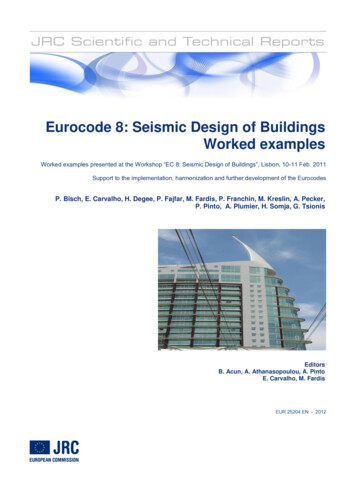
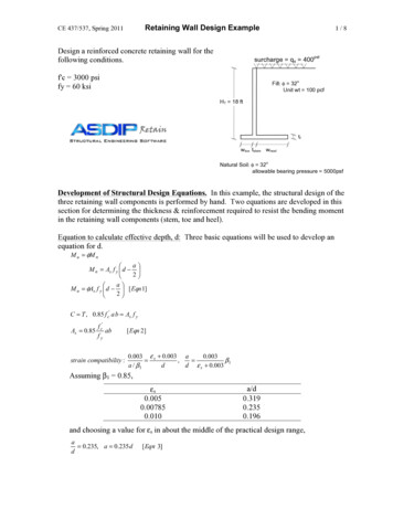
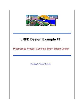
Distance of anchor from top of wall 1.2 m (from trial and error during calculations, seebelow)Anchor inclination 15 degrees minimum to permit efficient grouting, 20 degrees required inthis case to achieve recommended cover depth of soil over anchor bond zoneAnchor free length. Minimum 3 m for bar anchor, 4 m for strand anchor, must extendbeyond the failure plane for the active soil wedge (which will be different for the gravity andearthquake cases). For this example, anchor free length 4 m (see Figure X.2.)Anchor bond length: To be determined.Step 1. Initial trial geometryThe depth of excavation and depth to each row of anchors needs to be estimated as a firststep, based on experience or trial and error. Typically from 1m to 2 m.Step 2. Prepare apparent earth pressure diagram (gravity case)The total load acting against the wall from earth pressure for gravity only is based on theearth pressure envelopes recommended by Terzaghi & Peck [1967] (Figure X.3) andmodified by Sabatini et. al. [1999] for tied-back walls (Figure X.4). For the earthquake loadcase, KA should be calculated using the M-O equations as KAEH. The interface friction anglebetween the back of the wall and the soil should be conservatively assumed 0, becausethe active soil wedge and wall may both move downwards together (i.e. without any verticalcomponent of friction).Figure X.3. Apparent earth pressure envelope for sand for braced excavation[Terzaghi & Peck, 1967]6
Figure X.4. Apparent earth pressure diagram for tied-back walls with one level ofground anchors in sand. [Source: Sabatini et. al., 1999]7
Step 3. Calculate anchor design load and reaction force required at base of wall (gravitycase)Step 4. Calculate pole bending moments (gravity case)8
Step 5. Determine depth of pole embedment (gravity case)Calculate required depth of embedment for soldier piles to resist wall base reaction usingBroms [1965] or similar. If the pole spacing is less than three diameters, then treat as acontinuous wall. For the worked example, it was assumed that the poles will be set into 500mm diameter holes and concrete filled. Therefore, the following calculations treat theembedded poles as a continuous palisade.(Note that in this case the internal stability check below was found to govern the depth ofembedment).Step 6. Check internal stability of the wall (gravity case)A possible internal failure mechanism is shown in Figure X.5 with an active failure wedgeimmediately behind the wall, a passive wedge immediately in front of the embedded toe ofthe wall, and the anchor(s) developing their proven test capacity (normally 1.33 times thedesign load or 80 percent of the anchor tensile capacity).The factor of safety should be FS 1.5 for the gravity case.9
Figure X.5. Internal and external failure mechanisms for tied back walls.[Source: Sabatini et.al 1999]10
Step 7. Prepare apparent earth pressure diagram (earthquake case)Step 8. Calculate anchor design load and reaction force required at base of wall(earthquake case)Note that the earthquake case gives a much greater anchor design load than the gravitycase, cf. 100 KN from Step 3.11
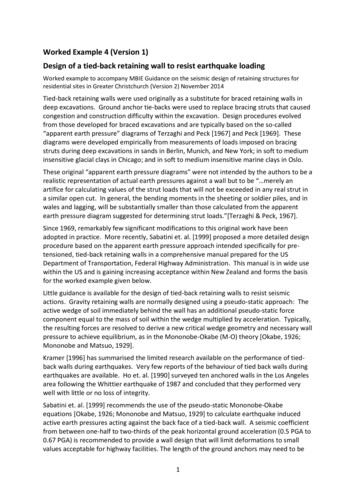
Step 9. Calculate pole bending moments (earthquake case)(Note that the critical factored bending moment in this case is similar to the gravity case inStep 4, cf. -31 KNm. Also, the load duration factor for timber (k1) is 1.0 for seismic and 0.6for long-term/permanent loading making the gravity case more critical for the example.However, both load-cases should be checked separately.)Step 10. Determine depth of embedment (earthquake case)Check that the depth of embedment of the poles is adequate for the earthquake case byconsidering a simplified sliding analysis as shown in Figure X.6. For the earthquake case, theundrained shear strength of the foundation soil may be assumed for Port Hills loess whencalculating the passive soil resistance, Su 50 KN/m2 was assumed for the example. Thepassive soil distribution is as shown in Figure X.6 with the cohesive contribution 2 c, c Su ,and Kp 1 for φ 0. Where the ground surface immediately in front of the wall is exposed,the cohesive component of passive resistance may be ineffective near to the ground surface12
because of desiccation and cracking. For the example, the upper 0.5 m of cohesive passiveresistance was neglected. For other situations where the ground surface is protected bypavement it may be appropriate to include the passive soil resistance over the full depth ofembedment, using judgement.Figure X.6. Analytical model for internal stability check (earthquake case).(Note that in this case the internal stability check below was found to govern the depth ofembedment).Step 11. Check internal stability of the wall (earthquake case)The factor of safety for the internal failure mechanism shown in Figure X.5 is checked againfor the earthquake case. Displacement of the wall during peak accelerations pulses maystretch the tendon and increase the amount of pre-load in the tendon. Rupture of the13
tendon is unlikely provided there is sufficient un-bonded free-length and the tendonmaterial is suitably ductile (e.g. Macalloy 1030 bar is rated at 6% minimum elongation,equivalent to 240 mm for the design example with a free length of 4 m)The factor of safety should be FS 1.0 for the earthquake case.Step 12. Selection of anchor.The earthquake case was found to govern the calculation of the design load for the anchor,with a required horizontal load of 171 KN @ 1.5 m spacing. A more efficient design mightbe to provide anchors at 3 m centres with short waler beams to spread the load betweenpairs of poles. For example: Anchor spacing 3 mAnchor inclination angle 20 degrees:Anchor design load 342 KN / Cos 20 364 KNAnchor test load 364 x 1.33 484 KNAnchor minimum characteristic tensile strength 484/0.8 605 KN(i.e. maximum test load 0.8 x anchor characteristic tensile strength)Refer to FHWA guidelines for more advice or BS 8081: 1989Step 13. External stability check.The external stability case (refer to Figure D5) is controlled by the total length of the groundanchor and should be checked once the anchor length has been determined. A wedgeanalysis may be undertaken using hand calculations or proprietary slope stability softwareused.For the worked example, analysis using PLAXIS indicated that a minimum anchor length of9.5 m would be required to achieve the desired FS 1 for the design acceleration kh 0.16.14
Other issues.The global stability of the wall and surrounds may need to be checked in certain cases, forexample where the ground in front of the retaining wall is sloping away. Also where there isweak ground below or in front of the toe of the wall.The axial capacity of the poles acting as piles may need to be checked in some cases, forexample where the anchor forces are very high or steeply inclined, and where the groundbelow the pole foundations is weak.15
Design of a tied-back retaining wall to resist earthquake loading . Worked example to accompany MBIE Guidance on the seismic design of retaining structures for residential sites in Greater Christchurch (Version 2) November 2014 . Tied-back retaining walls were used originally as a substitute for braced retaining walls in deep excavations.