Transcription
The Study on Disaster Risk Management for Narayangharh-Mugling HighwayTechnical GuideCHAPTER 6RETAINING AND REINFOCED EARTH WALL WORKS6.1GeneralRetaining walls are structures, which support and retain earth in order to prevent failure ofsediments in the places where stability of slope can not be assured by ground condition itself orby other slope protection works.Along the N-M highway, a lot of retaining walls, which consist mainly of gravity type concretewall, block masonry wall and gabion wall, have been constructed. However, a large number ofstructural deformation and failure on the retaining walls were visibly and clearly observable.The main problems regarding to the retaining walls are listed as follows:a) No or no enough geotechnical investigations were conducted to obtain foundationinformation for the design of retaining walls. Some retaining walls rest on loose and softground that has no enough bearing capacity to support the retaining structures.b) No or less foundation works were executed. Some retaining walls were placed on depositlayers without foundation treatment, which is the main cause of retaining structuredamage.c) In some cases, retaining walls are misused because of the failure masses or earth pressurethat may be the several time larger than the wedge of earth retained by these retainingwalls. To be effective, the wedge of earth supported by the wall should be similar orlarger in size to that of the failed or potential failure mass. If the potential failure mass ismuch larger than the wedge of earth that the retaining wall can potentially retain, atieback system or some other method of stabilization should be used in combination.d) In some cases, anti-proof sand treatment (geotextile and filter material) behind the wallswere not designed and executed. This may cause flow out of backfilling materials,leading to soil subsidence behind the wall and subsequent deformation and collapse ofthe retaining wall.e) Drainage treatment behind retaining walls was hardly done. High water pressure behindwall body was produced during and after heavy rainfall because of no drainage treatment,and deformed the retaining structures together with earth pressure. In principle, all wallsJICA6-1February 2009
The Study on Disaster Risk Management for Narayangharh-Mugling HighwayTechnical Guideshould be provided with weep holes. The weep holes are placed horizontally at the lowestpoints where free outlets for water may be obtained and should be spaced at not morethan 2.0 m center to center in a staggered manner. The length of the weep hole should notbe less than the thickness of the walls and should be at least 50 mm diameter PVC, andmust be provided with filter material covered with geotextile filter fabric.This chapter, focusing the above-mentioned problems, discusses consideration points inplanning, designing and constructing a retaining wall.In addition, as a new method, reinforced earth walls, which has the function of a retaining wall,has been widely used in unstable sites in mountainous areas in recent years. It is a technicallyattractive and cost-effective technique for increasing the stability of natural soil andconstructed fill slopes and for reducing earth pressures against retaining walls. The method isideal for very high or heavily loaded retaining walls because of its high load-carryingcapacity. The method is thus introduced in this technical guide, in consideration of itsapplicability in Nepal in the future.JICA6-2February 2009
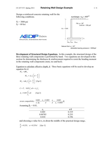
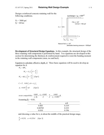
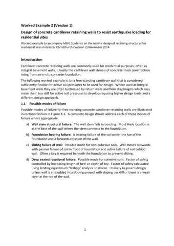
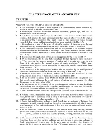
The Study on Disaster Risk Management for Narayangharh-Mugling Highway6.2General Considerations6.2.1Classification of Retaining WallsTechnical GuideRetaining walls are generally classified into the following types in accordance with shapes,characteristics, design criteria and applications.a) Stone (or block) masonry retaining wallb) Gravity type retaining wallc) Supported type retaining walld) Cantilever beam type retaining walle) Counterfort type retaining wallf)Buttress type retaining wallg) Gabion retaining wallTable 6.2.1 summarizes retaining wall types and their characteristics.6.2.2Application of Retaining WallsAs summarized in Table 6.2.1 below, selection of the type of retaining wall is generally based onthe topographical and geological conditions at the place of the wall construction, work conditions,purpose of retaining wall, and height of wall.Retaining walls are used to correct highway failures by increasing the forces tending to resistfailures. Generally, retaining wall is placed at the toe of the distressed area or potential slopefailure.Retaining walls have some potential applications as follows:a) To maintain the stability of the foot part of a slope after being distressed (Figure 6.2.1),b) To prevent small-scale shallow collapse and toe collapse of large-scale slope failures,c) To support slope fattening and berm fills,d) To function as a foundation for other slope protection works such as crib works,e) To catch rock fall mater in order to protect vehicles from rock fall (Figure 6.2.2), andf) To provide road space especially where right of way is limited.JICA6-3February 2009
The Study on Disaster Risk Management for Narayangharh-Mugling everCounterfortJICATable 6.2.1 Types and Characteristics of Retaining WallsHeight andShapeCharacteristicsGradientTechnical GuideTechnical Note Normally lessthan 7.0 m inheight. Up to 15.0 m inheight for largeblock masonry. Front slope is1:0.3 to 1:0.6(V:H) Frequentlyused to preventsmall scalecollapse at thefoot of theslope or toprotect theslope. Less than 5.0 min height. The width ofwall base isabout 0.5 to 0.7times theheight of thewall. Supports theearth pressureby itsdeadweight. Less than 10.0m in mostcases. Up to 15.0 m insome cases. Front slope is1:0.3 to 1:0.6(V:H) Supports theearth pressureby its owndeadweightwhile beingsupported bythe earth at therear or by thebackfill. Applicable forwidening theexisting road inmountainousterrain. Frequentlyused in placeswith land andtopographicalconstraints. 3.0 to 10.0 m inheight. The width ofwall base isabout 0.5 to 0.8times theheight of wall. Vertical wallresist the lateralload or earthpressure. The weight ofbackfill overthe heel slabcan be used tosupport theearth pressure. Applicable forpilefoundations. Precastconcrete isfrequentlyused. More than 10.0m in height. The width ofwall base isabout 0.5 to 0.7times theheight of wall Vertical walland bottom slabas slab issupported onthree sides. Counterforttype is morebeneficial thancantilever typefor higherwalls. Construction ofwall body andbackfill isdifficult. Applicable forpilefoundations.6-4 Mainlyapplicable forlight earthpressure loadswhere the soilbehind the wallis dense orgood soilsediment. Structurallyweak to resistthe effects ofan earthquake. Applicable ongood groundfoundationsbecause ofgreat groundreaction. Inapplicablefor pilefoundations.February 2009
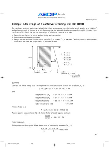
The Study on Disaster Risk Management for Narayangharh-Mugling HighwayTechnical GuideColluvial depositColluvial depositGabion wallConcrete retaining wallGabion wallBedrockRoadRoada) Slope foot protection by gabion wallb) Slope foot protection by retaining wallFigure 6.2.1 Schematic Diagram of Slope Foot ProtectionOriginal ground lineGabion catch wallCatch fenceCatch ditchConcret catch walllRoadRoadb) Catch wall Catch fencea) Catch ditch Catch wallFigure 6.2.2 Schematic Diagram of Rock Fall Protection6.2.3Design Procedure of Retaining WallFigure 6.2.3 shows the design procedure of retaining wall works. The following sections willgive brief descriptions of design procedures for retaining walls.(1)Selection of types of structuresAs shown in Table 6.2.1 before, there are many types of structures for retaining walls and theselection of type of structures are dependent mainly on the topographical and geologicalconditions at the place of the wall construction, work conditions, purpose of retaining wall, andheight of walls.(2)Selection of foundation typesThe types of foundations for a retaining wall are principally classified into spread foundationsJICA6-5February 2009
The Study on Disaster Risk Management for Narayangharh-Mugling HighwayTechnical Guideand pile foundations. The preferable type of foundations for a retaining wall are spreadfoundation in view of their movement together with the bearing stratum and the filling materialat the back. In some cases, if surface layer is soft, spread foundations can also beused withthe replacement or improvement of the soft layer. Pile foundations are used when theapplication of spread foundations are difficult.1) Selection of Structural Types2) Selection of Foundation Type3) Determination of Design Condition4) Examination of Earquake Effect5) Assumption of Sectional Shape of Wall6) Calculation and Conbination of Loads7) Stability Analysis for Wall andFoundation GroundFigure 6.2.3 Flowchart of Retaining Wall Design(3)Determination of Design Conditionsa)Parameters for shearing strength of soilThe parameters for shear strength of soil are generally obtained from either unconfinedcompression test or the triaxial compression test. The empirical relationship with N value can beused to obtain parameters of soils as follows:Cohesion c of clayey soilsc 6 N 10 N(kN/m2)Internal friction angle φ of sandy soilφ 15 15 N 45 b)N 5Unit weight of soilThe unit weight of soil γ(kN/m3) used for the calculation of earth pressure is obtained fromJICA6-6February 2009
The Study on Disaster Risk Management for Narayangharh-Mugling HighwayTechnical Guidelaboratory of soil samples. If it is difficult to conduct soil test, the values shown in Table 6.2.2can be used instead of soil test results.Table 6.2.2 Unit Weight of Soils (Unit: kN/m3)Type of GroundSoil TypeNatural groundEmbankmentLoose soilDense soilSand and gravel1820Sandy soil1719Clayey soil1418Sand and gravel20Sandy soil19Clayey soil (WL 50%)18Note: the value achieved by subtracting 9 kN/m3 from the values in the table can be used as the unit weight of soilbelow the groundwater level.Source: Manual for Retaining Wall, Published by Japan Road Association, March 1999c)Allowable bearing capacity of groundThe allowable bearing capacity of ground is, in principle, determined by conducting an in-situtest (standard penetration test). When it is difficult to conduct an in-situ test for retaining wall,the values shown in Table 6.2.3 can be used.Table 6.2.3 Estimated Design Constant of Bearing GroundBearing ueSlightly cracked hard rock1000.7Over 100―Highly cracked hard rock600.70ver 100―Soft rock300.70ver 100―Dense300.6――Loose300.6――Dense300.630 – 50Slightly dense200.515 – 30Stiff or very firm200.52.0 – 4.015 – 30Firm100.451.0 – 2.08 – 15Soft or slightly firm50.5 – 1.04-8Note: qa Allowable bearing capacity, μ Coefficient of friction between bearing ground and wall base, qu uniaxial compressive strength.Source: Manual for Retaining Wall, Published by Japan Road Association, March 1999JICA6-7February 2009
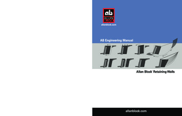
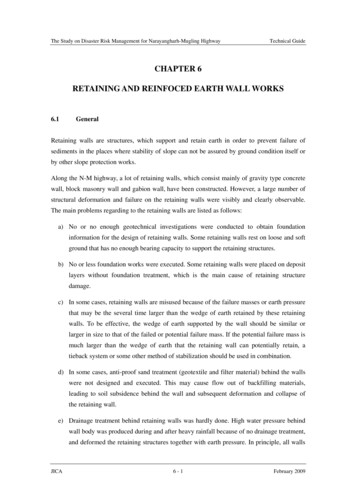
The Study on Disaster Risk Management for Narayangharh-Mugling Highwayd)Technical GuideFriction angle φB and cohesion cB between foundation base and groundWhen the shear parameters c and φ of the bearing stratum are obtained by soil test, thefriction angle of the foundation baseφB is determined to beφB φfor cast-in-place concreteretaining wall andφB 2/3φ for precast concrete retaining wall.If it is difficult to conduct a soil test, the values shown in Table 6.2.4 can be used.Table 6.2.4 Friction Coefficient and Cohesion between Foundation Base and GroundCondition of shearing l layer0.6―Sandy soil0.6―Clayey soil0.5―Type of bearing groundRock/Gravel and ConcreteLaying of rubble or crushed stone betweenfoundation ground and concreteNotes: 1) ― not considered, 2) in the case of precast concrete, the friction coefficient is regarded as notexceeding 0.6 even if the foundation is bedrock.Source: Manual for Retaining Wall, Published by Japan Road Association, March 1999(4)Examination of Earthquake EffectsIn Japan, the effects of earthquakes need to be considered when designing retaining walls higherthan 8 meters. Accordingly, it is suggested that analysis of stability against earthquake should bemade for retaining wall of up to 8 m in height when the importance of retaining wall and thedifficulty of it restoration demand such analysis.(5)Calculation and Combination of LoadsGenerally, loads acting on a retaining wall include a) deadweight, b) surcharge, c) earth pressure,d) buoyancy below the base of wall body, e) water pressure behind wall body, and f) earthquakeload.However, for design purposes, loads acting on a retaining wall are normally considered as (a)deadweight, (b) surcharge and (c) earth pressure.Design calculations against earthquakes are generally not required for ordinary retaining wallsbecause the load increase due to the seismic force can be compensated by a slightly increasedfactor of safety for the normal design calculations and by a resisting force which can not beconsidered in the calculations.In addition, as a retaining wall is a structure which is in contact with the earth, it is subject toearth pressure to the wall. The earth pressure caused by about-to-collapse bank soil due toJICA6-8February 2009
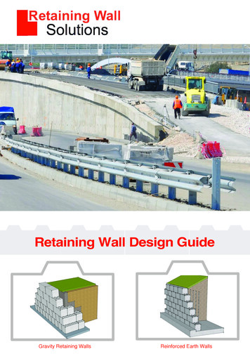
The Study on Disaster Risk Management for Narayangharh-Mugling HighwayTechnical Guideforward movement of the wall, i.e. in the direction away from the embankment; it called theactive earth pressure. As the purpose of a retaining wall is to support an about-to-collapse soilmass, it is generally designed based on the active earth pressure.The active earth pressure acting on movable walls is calculated by the following Coulomb’sformula:123435W3HαHδP3R3 φω(b) Assumed Soil Wedge(a) Wedge AnalysisP390 -(α δ)90 -(ω-φ-α-δ)R3W3ω-φ(c) Link Polygon1) Assumption of slip surfaceAssume a glide slip surface from the heel of
In addition, as a new method, reinforced earth walls, which has the function of a retaining wall, . Figure 6.2.3 shows the design procedure of retaining wall works. The following sections will give brief descriptions of design procedures for retaining walls. (1) Selection of types of structures As shown in Table 6.2.1 before, there are many types of structures for retaining walls and the .