Transcription
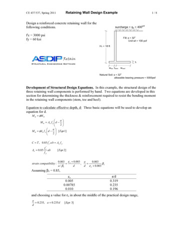
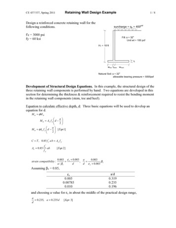
Retaining Wall Design ExampleCE 437/537, Spring 2011Design a reinforced concrete retaining wall for thefollowing conditions.1/8surcharge qs 400f'c 3000 psify 60 ksipsfFill: φ 32oUnit wt 100 pcfHT 18 fttfwtoe tstem wheelNatural Soil: φ 32oallowable bearing pressure 5000psfDevelopment of Structural Design Equations. In this example, the structural design of thethree retaining wall components is performed by hand. Two equations are developed in thissection for determining the thickness & reinforcement required to resist the bending momentin the retaining wall components (stem, toe and heel).Equation to calculate effective depth, d: Three basic equations will be used to develop anequation for d.M u φM na M n As f y d 2 a M u φAs f y d [ Eqn 1]2 C T , 0.85 f c' a b As f yAs 0.85f c'abfystrain compatibility :[ Eqn 2]0.003 ε s 0.003 a0.003 , β1a / β1dd ε s 0.003Assuming β1 0.85,εs0.0050.007850.010a/d0.3190.2350.196and choosing a value for εs in about the middle of the practical design range,a 0.235, a 0.235 dd[ Eqn 3]
CE 437/537, Spring 2011Retaining Wall Design Example2/8Substituting Eqn. 2 into Eqn. 1: f' a M u φ 0.85 c ab f y d f2 y And substituting Eqn. 3 into the above:M u φ 0.85f c'0.235 d 0.235d b f y d fy2 0.883dInserting the material properties: f'c 3 ksi and fy 60 ksi, and b 12in (1-foot-widestrip of wall, in the direction out of the paper).kM u 0.90(0.85) 3ksi (12 in )(0.235)(0.883)d 2M u 5.71 in d 2Equation for area of reinforcement, As. The area of reinforcement required is calculatedfrom Eqn. 1:M u φ As f y 0.883d 0.90 As 60 ksi 0.883 dM u 47.7 ksi As dDesign Procedure (after Phil Ferguson, Univ. Texas)1. Determine HT. Usually, the top-of-wall elevation is determined by the client. Thebottom-of-wall elevation is determined by foundation conditions.HT 18 feet.2. Estimate thickness of base. tf 7% to 10% HT (12" minimum)Tf 0.07 (18' x 12"/') 15.1"use tf 16"
Retaining Wall Design ExampleCE 437/537, Spring 20113/83. Design stem (tstem, Asstem). The stem is a vertical cantilever beam, acted on by thehorizontal earth pressure.ftinh 8 – 16 /12fth 16.67in/fthtf 16inka γ hka qswtoe tstem wheelcalc. d:Pfill Pfill 1( k a γ h ) h (1 ft out of page)21 sin φ 1 sin( 32 o )ka 0.311 sin φ 1 sin( 32 o )1(0.31)(100 pcf )(16.67 ft ) 2 (1 ft ) 4310 lb2Psur k a q sur h (1 ft ) 0.31 ( 400 psf )(16.67 ft )(1 ft ) 2070 lbhhM u ( Earth Pressure LoadFactor)( Pfill )( ) ( Live LoadFactor)(Psur )( )32ftft16.6716.67M u (1.6)(4310 lb )() (1.6)(2070 lb )() 65.9 k ft32Mu kin5.71d2kin) 5.71 in d 2 , d 11.8inft1t stem 11.8in 2 in cover (1.0 in ) 14.3in , ( assume #8 bars )2ininind 15 2 0.5 12.5in65.9 k ft (12use t stem 15in
CE 437/537, Spring 2011Retaining Wall Design Example4/8calc. As:M u 47.7 ksi As d65.9 k ft (12in) 47.7 ksi As (12.5in ), As 1.33 in 2ftAs of one #8 bar 0.79 in 2in 2ininbar12 7.13,2ftbarin1.33ft of wall0.79use #8 @ 6 in4. Choose Heel Width, wheel Select wheel to prevent sliding. Use a key to force slidingfailure to occur in the soil (soil-to-soil has higher friction angle than soil-to-concrete).12inNeglect soil resistance in front of thewall.Fresist FslidingFSFS Factor of Safety 1.5 for slidingset18ftFresist (Vertical Force)(coefficient of friction)Fresist WT (tan φnatural soil )tf 16intan φnatural soil tan(32 o ) 0.62WT W fill Wstem W foundW fill (100 pcf )(16.67 ft )( wheel )(1 ft ) 167015inlbwheelft12 in 15in 1 ft(1 ft ) 2810 lbin212 )1615 (150 pcf )( ft )( wheel ft 3 ft )(1 ft ) 200 plf wheel 8501212Wstem (150 pcf )(16.67 ft )(W foundFsliding Pfill Psur1(0.31 100 pcf )(18 ft ) 2 (1 ft ) 5020 lb2 (0.31 400 psf )(18 ft )(1 ft ) 2230 lbPfill PsurFsliding 5020 lb 2230 lb 7250 lb
CE 437/537, Spring 2011Retaining Wall Design Example5/8 lblblblb 1670 ft wheel 2810 200 ft wheel 850 (0.62) 7250lb 1.51.5lb7250lb 3660lb 1870 wheel , wheel 7.42 ft ,0.62ftuse wheel 7.5 ft5. Check Overturning.12in18 ft18 ft) Psur ()32 5.02 k (6 ft ) 2.23k (9 ft ) 50.2 k ftM over P fill (M over18ft7.5 ft 15 ft 3 ft ), assume wtoe 3 ft2121.25 ft Wstem (3 ft )23' 15" 7.5'11.75 ft W found ()2 (1.67 klf 7.5 ft )(8 ft ) ( 2.81k )(3.625 ft ) (0.20klf 7.5 ft 0.85k )(5.875 ft )M resist W fill (M resist12.53k2.35kM resist 124.2 k ftM resist 124.2 k ft 2.47 2.0 FSover , OKM over50.2 k ft6. Check Bearing.WTML , equation is valid only if e bL bL266 W foundσ v at end of toe WT W fill WstemWT 12.45 k 2.81k 2.35 k 17.69 k7.5 ft1.25 ft) Wstem (7.5 ft 5.875 ft ) W found (0)22 12.53k ( 2.125 ft ) 2.81k ( 2.25 ft ) 29.9 k ftM M over W fill (5.875 ft M 50.2 k ftCheck that e L/6:e m29.9 k ftL 11.75 ftLft 1.68, 1.96 ft , e , OKkWT66617.69tf 16in
Retaining Wall Design ExampleCE 437/537, Spring 2011σv 17.69 kftft(1 )(11.75 ) 29.9 k ft1 ft(1 )(11.75 ft ) 266/8 2.80 ksf 5.0 ksf allowable bearing capacity, OK7. Heel Design.Max. load on heel is due to the weight of heel fill surcharge as the wall tries to tip over.Flexure:W Wheel W fill Wsur16ft )(1 ft )12 1.2(100 pcf )(16.67 ft )(1 ft )W 1.2(150 pcf )( 1.6( 400 plf )W 2.88Mu Vuwu16Mu7.5inftklfwu L2 2.88klf (7.5 ft ) 2 81.0 k ft22k 2dinink81.0 k ft (12 ) 5.71 d 2 , d 13.0in for flexureftinM u 5.71Shear:Vu wu (7.5 ft ) 2.88 klf (7.5 ft ) 21.6 kφVc (0.75) 2 f c' bw d (0.75) 2 3000 psi (12 in ) dsetVu φVc ,21,600lb (0.75) 2 3000 psi (12 in ) d , d 21.9 in for shear, controlsShear controls the thickness of the heel.1t heel 21.9 in 2 in cover in 24.4 in (assume #8 bar ),2use t heel 21.5 inReinforcement in heel:M u 47.7 ksi As din81.0 k ft (12 ) 47.7 ksi As (21.9 in ), As 1.07in 2ftin 20.79bar (12 in ) 8.83 in ,ftin 21.07ftuse #8 @ 8"
Retaining Wall Design ExampleCE 437/537, Spring 20117/88. Toe Design.Earth Pressure at Tip of Toe:WuMu bL 1 2bL6Wu 1.2(W fill Wstem W found ) 1.6 (Wsur )σv Wu 1.2(12.53k 2.81k 2.35k ) 1.6(0.4 ksf )(18 ft )(1 ft ) 32.7 k , (did not recalc foundation wt b.c. neglible change)M u 1.6 M over 1.2(Wsoil 2.125 ft Wstem 1.0 ft )3' 1.25'7.5'[]M u 1.6(50.2 k ft ) 1.2 12.53k ( 2.125 ft ) 2.81k (1 ft ) 45.0k ft32.7 k45.0k ft (1 ft )(11.75 ft ) 1 (1 ft )(11.75 ft ) 26ksf 2.78 1.96ksf 4.74 ksfσv σ vAσ vC 2.78ksfσ vB 0.82 ksf 1.96ksf 0.82 ksfAB4.74 ksf 0.82 ksf(8.75 ft ) 3.74 ksf11.75 ftd for flexure:M u (3.74 ksf )(3 ft )(1 ft )(3 ft12) (1.00 ksf )(3 ft )(1 ft )( 3 ft ) 19.8k ft223k 2dinink19.8k ft (12 ) 5.71 d 2 , d 6.5in for flexureftinM u 5.71d for shear:Assume theel ttoe 21.5inCritical section for shear occurs at "d" from face of stem, d 21.5" – 3"cover-1/2" 18"σ vcritical sec tion 0.82 ksf Vu 4.74 ksf 0.82 ksf18(8.75 ft ft ) 4.24 ksfft1211.75118( 4.74 ksf 4.24 ksf )(3 ft ft )(1 ft ) 6.74 k212φVc (.75)2 3000 psi (12in )(18in ) 17,750lb Vu , OK , d for flexure controlsC
CE 437/537, Spring 2011Retaining Wall Design Example8/8Reinforcement in toe:M u 47.7 ksi As d19.8k ft (12in) 47.7 ksi As (18in ), As 0.28 in 2ftin 2bar (12 in ) 33in , try smaller bars , say #4ftin 20.28ft0.79in 2bar (12 in ) 8.6inftin 20.28ft0.20use #4 @ 8"
Design a reinforced concrete retaining wall for the following conditions. f'c 3000 psi fy 60 ksi Natural Soil Development of Structural Design Equations. In this example, the structural design of the three retaining wall components is performed by hand. Two equations are developed in this section for determining the thickness & reinforcement required to resist the bending moment in the .