Transcription
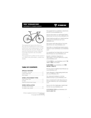
Product Data SheetJune 201300813-0100-4030, Rev GBRosemount 2120Full-featured Vibrating Fork Liquid Level Switch Function virtually unaffected by flow, bubbles,turbulence, foam, vibration, solids content,coating products, liquid properties, andproduct variations Adjustable switching delay for turbulent orsplashing applications Magnetic test point makes functional test easyNo need for calibration and requires aminimum amount of installation “Fast Drip” fork design gives quicker response Explosion-proof/Flameproof andIntrinsically Safe options Easy terminal access, polarity insensitive,and short circuit protection Electronic self-checking and conditionmonitoring
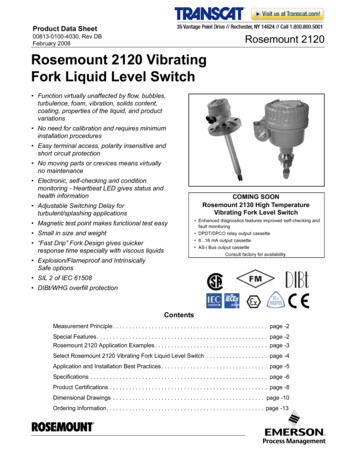
Rosemount 2120June 2013Overview of the Rosemount 2120Measurement principleThe Rosemount 2120 is designed using the principle of a tuning fork.A piezo-electric crystal oscillates the forks at their natural frequency.Changes to this frequency are continuously monitored. The frequencyof the vibrating fork sensor changes depending on the medium inwhich it is immersed. The denser the liquid, the lower the frequency.When used as a low level alarm, the liquid in the tank or pipe drainsdown past the fork, causing a change of natural frequency that isdetected by the electronics and switches the output state.Adjustable Mode and Switching DelayWhen the 2120 is used as a high level alarm, the liquid rises in the tankor pipe, making contact with the fork which then causes the outputstate to switch.Key features and benefits‘Fast Drip’ Forks Virtually unaffected by turbulence, foam, vibration, solids content,coating products, or liquid properties The 2120 is designed for operation in process temperatures from–40 to 302 F (–40 to 150 C) A ‘heartbeat’ LED indicates its operating state. The LED also flasheswhen the switch output is ‘off’ and is constantly lit when 'on' Adjustable switching delay prevents false switching in turbulent orsplashing applications ‘Fast Drip’ fork design gives quicker response time, especially withviscous liquids Rapid wet-to-dry and dry-to-wet time setting for highly responsiveswitching Fork shape is optimized for hand polishing to meet hygienicrequirements No moving parts or crevices for virtually no maintenanceContentsOverview of the Rosemount 2120 . . . . . . . . . . . . . . page 2Product certifications . . . . . . . . . . . . . . . . . page 11Rosemount 2120 level switch ordering . . . . . . . . . page 4Dimensional drawings . . . . . . . . . . . . . . . . page 13Specifications . . . . . . . . . . . . . . . . . . . . . . . . . . . . . . . page 82www.rosemount.com
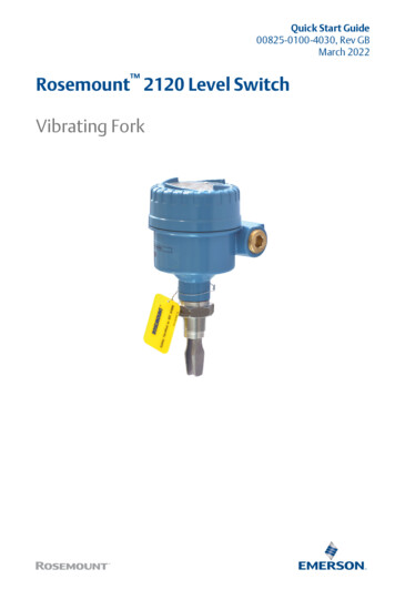
June 2013Rosemount 2120Fit and forget Once installed, the 2120 is ready to go.It needs no calibration and requires minimum installation The ‘heartbeat’ LED gives an instant visual indication that the unit isoperational Functional testing of the instrument and system is easy with a magnetictest point High And Low Level AlarmYou can install, and forget itSuperior performance The 2120 is a popular choice for high and low level alarm and pump controlduties for its simplicity, ease of use, and reliability Functionality is virtually unaffected by flow, turbulence, bubbles, foam, orvibration The ‘Fast Drip’ design allows the liquid to be quickly drawn away from thefork tip when mounted horizontally, making the 2120 quicker and moreresponsive in high density or viscous liquid applications High-temperature ApplicationsWith a user-selectable time delay feature, the risk of false switching isminimized in turbulent or splashing applicationsApplications Overfill protection High and low level alarms Pump control or limit detection Run dry or pump protection Hygienic applications High-temperature applications Wireless applicationsPump Control / Limit DetectionWireless Applications using aRosemount 702 Discrete Transmitterwww.rosemount.com3
Rosemount 2120June 2013Rosemount 2120 level switch orderingTable 1. 2120 ordering information The Standard offering represents the most common models and options. These options should be selected for best delivery.The Expanded offering is manufactured after receipt of order and is subject to additional delivery lead time.ModelProduct Description2120Vibrating Fork Liquid Level Switch / –40 302 F (–40.150 C)Materials of Construction: Process Connection/ForkStandardStandard D316/316L Stainless Steel (1.4401/1.4404) dual certifiedExpandedF(1)ECTFE/PFA copolymer, coated 316/316L SST (1.4401/1.4404)C(2)Alloy C (UNS N10002), Alloy C-276 (UNS N10276), SolidProcess Connection Size / TypeStandardStandard0A3/4-in. BSPT (R) Thread 0B3/4-in. BSPP (G) Thread 0D3/4-in. NPT Thread 1A1-in. BSPT (R) Thread 1B1-in. BSPP (G) Thread 1D1-in. NPT Thread – (2-in. NPT Thread available by adding “R2105” to the model number ) 1P1-in. BSPP (G), O-ring, Hygienic Fitting 5R11/2-in. (38 mm) Tri-Clamp, Hygienic Fitting 2R2-in. (51 mm) Tri-Clamp, Hygienic Fitting 1G1-in. ASME B16.5 Class 150 Raised Face (RF) Flange 1H1-in. ASME B16.5 Class 300 Raised Face (RF) Flange 1J1-in. ASME B16.5 Class 600 Raised Face (RF) Flange (3)5G1 /2-in. ASME B16.5 Class 150 Raised Face (RF) Flange 5H11/2-in. ASME B16.5 Class 300 Raised Face (RF) Flange 2G2-in. ASME B16.5 Class 150 Raised Face (RF) Flange 2H2-in. ASME B16.5 Class 300 Raised Face (RF) Flange 3G3-in. ASME B16.5 Class 150 Raised Face (RF) Flange 3H3-in. ASME B16.5 Class 300 Raised Face (RF) Flange 4G4-in. ASME B16.5 Class 150 Raised Face (RF) Flange 4H4-in. ASME B16.5 Class 300 Raised Face (RF) Flange 1KDN25, EN1092 PN 10/16 Flange 1LDN25, EN1092 PN 25/40 Flange 1MDN25, EN1092 PN 63 Flange 1NDN25, EN1092 PN 100 Flange 5KDN40, EN1092 PN 10/16 Flange 5LDN40, EN1092 PN 25/40 Flange 2KDN50, EN1092 PN 10/16 Flange 2LDN50, EN1092 PN 25/40 Flange 7KDN65, EN1092 PN 10/16 Flange 7LDN65, EN1092 PN 25/40 Flange 3KDN80, EN1092 PN 10/16 Flange 3LDN80, EN1092 PN 25/40 Flange 4KDN100, EN1092 PN 10/16 Flange 4LDN100, EN1092 PN 25/40 FlangeExpanded 15J11/2-in. ASME B16.5 Class 600 Raised Face (RF) Flange2J2-in. ASME B16.5 Class 600 Raised Face (RF) Flange3J3-in. ASME B16.5 Class 600 Raised Face (RF) Flange4www.rosemount.com
June 2013Rosemount 2120Table 1. 2120 ordering information The Standard offering represents the most common models and options. These options should be selected for best delivery.The Expanded offering is manufactured after receipt of order and is subject to additional delivery lead time.4J4-in. ASME B16.5 Class 600 Raised Face (RF) Flange5MDN40, EN1092 PN 63 Flange5NDN40, EN1092 PN 100 Flange2MDN50, EN1092 PN 63 Flange2NDN50, EN1092 PN 100 Flange7MDN65, EN1092 PN 63 Flange7NDN65, EN1092 PN 100 Flange3MDN80, EN1092 PN 63 Flange3NDN80, EN1092 PN 100 Flange4MDN100, EN1092 PN 63 Flange4NDN100, EN1092 PN 100 FlangeSA25A, 10K, JIS B2220 FlangeSB25A, 20K, JIS B2220 FlangeTA40A, 10K, JIS B2220 FlangeTB40A, 20K, JIS B2220 FlangeUA50A, 10K, JIS B2220 FlangeUB50A, 20K, JIS B2220 FlangeVA80A, 10K, JIS B2220 FlangeVB80A, 20K, JIS B2220 FlangeZA100A, 10K, JIS B2220 FlangeZB100A, 20K, JIS B2220 FlangeXX(4)Customer SpecificElectronic TypeAvailable CertificationsStandardStandardTDirect load switching (Mains 2-wire) 20 to 264 Vac 50/60Hz, 20 to 60 VdcNA, E1, E2, E5, E6, E7, G5, G6 GPNP/PLC low voltage (3-wire) 20 to 60 VdcNA, E1, E2, E5, E6, E7, G5, G6 VRelay DPCO – (9.30 Vdc version available by adding “R2257” to model number(3)(5))NA, E1, E2, E5, E6, E7, G5, G6 KNAMURAll H8/16 mAAll Surface FinishAvailable ConnectionsStandardStandard1Standard surface finish2Hand polished (Ra 0.4 μm)Product CertificationsAll Hygienic Connection Only Electronic Types AllowedAvailable HousingsAll except 9.30 Vdc RelayAll StandardStandardNANo Hazardous Locations CertificationsG5(6)FM Ordinary Locations (unclassified, safe area)AllY, T G6(7)CSA Ordinary Locations (unclassified, safe area)All except 9.30 Vdc RelayY, T E1ATEX FlameproofAll except 9.30 Vdc RelayX, S E2INMETRO FlameproofAll except 9.30 Vdc RelayX, S E5(6)FM Explosion-proofAllY, T E6(7)CSA Explosion-proofAll except 9.30 Vdc RelayY, T E7IECEx Explosion-proofAll except 9.30 Vdc RelayX, S I1ATEX Intrinsic SafetyK, HAll I2INMETRO Intrinsic SafetyK, HAll I5FM Intrinsic SafetyK, HAll CSA Intrinsically SafeK, HAll IECEx Intrinsic SafetyK, HAll I6I7www.rosemount.com5
Rosemount 2120June 2013Table 1. 2120 ordering information The Standard offering represents the most common models and options. These options should be selected for best delivery.The Expanded offering is manufactured after receipt of order and is subject to additional delivery lead time.HousingAvailable for CertificationsStandardStandardAGlass Filled Nylon, M20 conduits/cable threadsNA, I1, I2, I5, I6, I7 DGlass Filled Nylon, 1/2-in. NPT conduits/cable threadsNA, I1, I2, I5, I6, I7 XAluminum Alloy, M20 conduits/cable threadsAll except G5, G6, E5, E6 YAluminum Alloy, 3/4-in. NPT conduits/cable threadsAll except E1, E2, and E7 SStainless Steel, M20 conduits/cable threadsAll except G5, G6, E5, E6 TStainless Steel 3/4-in. NPT conduits/cable threadsAll except E1, E2, and E7 Fork LengthAvailable ConnectionStandardAStandard length 1.7 in. (44 mm)H(8)EStandard(9)All except flanged and 2-in. NPT All flanged models All except 1-in. BSPP O-ring (1P) All except 1-in. BSPP O-ring (1P) Standard length flange 4.0 in. (102 mm)Extended, customer specified length in tenths of inches(9)MExtended, customer specified length in millimetersSpecific Extended Fork LengthStandardStandard0000Factory default length (only if Fork Length A or H is selected) XXXX(9)OPTIONSSpecific customer specified length in tenths of inches, or millimeters (XXXX mm or XXX.X inches) Calibration Data CertificationStandardStandard Q4Certificate of functional testMaterial Traceability CertificationStandardStandard Q8(8)(10)Material traceability certification per EN 10204 3.1Material CertificationStandardQ15(8)(10)Standard NACE MR0175 / ISO 15156 Q25(8)(10) NACE MR0103Special ProceduresStandardStandard P1(11)Hydrostatic testing with certificateTypical Model Number: 2120 D 0A K 1 I1 A 0000 Q8(1) ECTFE/PFA copolymer coating is only available for a flanged 2120 but excludes 1-in./DN25/25A flanges.Flanges are dual certified 316 and 316L Stainless Steel (1.4401 and 1.4404).(2) Available for threaded process connection codes 0A, 0D, 1A, and 1D and flanged process connections as standard, other upon request.(3) For a combination of 2-in. threaded process connection and 9 to 30 Vdc (12 Vdc nominal) version of the Relay electronics, add “R2258” to the model code.(4) Other process connections available upon request.(5) The 9 to 30 Vdc (12 Vdc nominal) version of the Relay electronics is available with Product Certification codes G5 or E5.(6) See “Product certifications” on page 11. E5 includes G5 requirements. G5 is for use in unclassified, safe area locations only.(7) See Product Certifications on page page 11. E6 includes G6 requirements. G6 is for use in unclassified, safe area locations only.(8) Not available for hand polished wet side.(9) Minimum length available for 3/4-in. threaded connection is 3.8 in. (95 mm); for 1-in. and 2-in. threaded, it is 3.7 in. (94 mm);for flanged, it is 3.5 in. (89 mm); and for Tri-Clamp, it is 4.1 in. (105 mm). Maximum length is 157.5 in. (4000 mm), except for ECTFE/PFA copolymer coating andhand-polished process where the maximum length is 59.1 in. (1500 mm) and 39.4 in. (1000 mm) respectively. Examples: Code E1181 is 118.1 inches. Code M3000 is 3000millimeters.(10) Only available for wetted parts.(11) Option limited to units with extended lengths up to 59.1-in. (1500 mm). Option is not available for ECTFE/PFA coating.6www.rosemount.com
June 2013Rosemount 2120Spare parts and accessoriesTable 2. Spare parts and accessories The Standard offering represents the most common models and options. These options should be selected for best delivery.The Expanded offering is manufactured after receipt of order and is subject to additional delivery lead time.Spares and Accessories (1) (2)StandardStandard02100-1000-0001Seal for 1-in. BSPP (G1A). Material: Non-asbestos BS7531 grade X carbon fiber with rubber binder 02100-1040-0001Seal for 3/4-in. BSPP (G3/4A). Material: Non-asbestos BS7531 grade X carbon fiber with rubber binder 02100-1010-0001Hygienic adaptor boss 1-in. BSPP. Material: 316 SST fitting. FPM/FKM O-ring 02100-1020-00012-in. (51 mm) Tri-clamp kit (vessel fitting, clamp ring, and seal). Material: 316 SST, NBR Nitrile 02100-1030-0001Telescopic test magnet 02120-2000-0001(3)11/2-in. BSPP adjustable 316 SST clamp gland for 1-in. extended lengths. Silicone (Si) rubber seal 02120-2000-0002(3)11/2-in. NPT adjustable 316 SST clamp gland for 1-in. extended lengths. Silicone (Si) rubber seal 02120-7000-0001Replacement Cassette: Direct load switching (2 Wire) (Red) 02120-7000-0002Replacement Cassette: PNP/PLC, low voltage (Yellow) 02120-7000-0003Replacement Cassette: NAMUR (Light Blue) 02120-7000-0004Replacement Cassette: Relay (DPCO), standard version (Green) 02120-7000-0005Replacement Cassette: 8/16 mA output (Dark Blue) 02120-7000-0007Replacement Cassette: Relay (DPCO), 9.30 Vdc (12 Vdc nominal) version (Green) (1) Check the Electronic Type and Product Certification sections in Table 1 on page 4 for availability conditions.(2) Intrinsically Safe (IS) approved cassettes can only be replaced with the same type of IS cassette. Non-IS cassette types can be interchanged with other non-IS cassettes, butthe new label must be fitted and the original part number transferred to the new label.(3) The adjustable clamp gland is not explosion-proof.www.rosemount.com7
Rosemount 2120June 2013Specifications Gasket material for 3/4-in. and 1-in. BSPP (G) is non-asbestos BS7531Grade X carbon fiber with rubber binderGeneralDimensional drawings See “Dimensional drawings” on page 13Product Rosemount 2120 Full-featured Vibrating Fork Liquid Level SwitchMeasuring principlePerformanceHysteresis (water) Vibrating Fork 0.039-in. ( 1 mm) nominalApplications Most liquids including coating liquids, aerated liquids, and slurriesSwitching point (water) 0.5 in. (13 mm) from tip (vertical) / from edge (horizontal) of fork(this will vary with different liquid densities)MechanicalFunctionalHousing / EnclosureMaximum operating pressureTable 3. Housing / Enclosure specification The final rating depends on the selected process connectionAHousingMaterialNylon PA6630%GFLED WindowConduit EntryIngressProtectionXYAl alloy ASTMB85 A360.0ST316C12 SSTYesNoNoNotApplicableNylon alHousing PaintD1/2-in.NPTIP66/67 toEN60529M20M203/4-in.NPTIP66/67 toEN60529,NEMA 4XM203/4-in.NPTIP66/67 toEN60529,NEMA 4XConnections Threaded, hygienic, and flanged process connections.See “Process Connection Size / Type” on page 4 for a complete listExtended lengths The maximum extended length is 157.5 in. (4000 mm) except forECTFE/PFA copolymer coating and hand-polished process connectionoptions which have a maximum length of 59.1 in. (1500 mm) and39.4 in. (1000 mm) respectivelyTable 4. Minimum extended lengths Threaded connection: see Figure 1 for operating pressuresNote: Clamp glands 02120-2000-0001 and 02120-2000-0002(page 7) limit the maximum pressure to 18.85 psig (1,3 bar g) Hygienic connection: 435 psig (30 bar g) Flanged connection:See Figure 1 or Table 5 (whichever gives the lowest pressure)Figure 1. Process pressureProcess Pressure psig (barg)Housing Code1450 (100)1160 (80)32 (0)-14.5 (-1.0)-40 32(-40) (0)122(50)302 Process(150) Temperature F ( C)Table 5. Maximum flange pressure ratingStandardClass/RatingSST FlangesASME B16.5Class 150275 psig(1)ASME B16.5Class 300720 psig(1)Process ConnectionMinimum Extended LengthASME B16.5Class 6001440 psig(1)3/4–in. Threaded3.8 in. (95 mm)EN1092-1PN 1010 barg(2)1–in. and 2-in. Threaded3.7 in. (94 mm)EN1092-1PN 1616 barg(2)Flanged3.5 in. (89 mm)EN1092-1PN 2525 barg(2)Tri-Clamp4.1 in. (105 mm)EN1092-1PN 4040 barg(2)EN1092-1PN 6363 barg(2)Process connection materialsEN1092-1PN 100100 barg(2) 316/316L Stainless Steel (1.4401/1.4404 dual certified)JIS B222010K14 barg(3) Alloy C (UNS N10002) and Alloy C-276 (UNS N10276)JIS B222020K34 barg(3)– available for flanged, and BSPT and NPT threaded process connections(3/4-in. and 1-in. BSPT (R), and 3/4-in. and 1-in. NPT) ECTFE/PFA co-polymer coated 316/316L Stainless Steel(1.4401/1.4404 dual certified)– only available for a flanged 2120 but excludes 1-in./DN25/25A flanges Hand-polished to better than 0.4 m option for hygienic connections8(1) At 100 F (38 C), the rating decreases with an increasing processtemperature.(2) At 122 F (50 C), the rating decreases with an increasing processtemperature.(3) At 248 F (120 C), the rating decreases with an increasing processtemperature.www.rosemount.com
June 2013Rosemount 2120Minimum and maximum operating temperatures See Figure 2 for operating temperatures Clamp glands 02120-2000-0001 and 02120-2000-0002 (page 7)limit the maximum temperature to 257 F (125 C) The ambient temperature for a 8/16 mA cassette is limited to158 F (70 C) in dust applicationsElectricalSwitching modeUser selectable switching mode (Dry on or Wet on)Protection Polarity insensitive– Relay (except 12 Vdc nominal version) and Direct Load electronicsFigure 2. Operating temperaturesAmbient Temperature F ( C) Over-current protection – Direct Load and PNP/PLC electronics Short-circuit protection – Direct Load and PNP/PLC electronics Load-missing protection – Direct Load and PNP/PLC electronics176 (80) Surge protection (to IEC61326) – Direct Load and PNP/PLC electronics122 (50)Heartbeat LED The 2120 has a status-indicating heartbeat LED, which can be seen at32 (0)-40 (-40)all times and from all angles through a lens in the cover (no lens inmetal housings)-40 32(-40) (0)140(60)302(150)Process Temperature F ( C)Liquid density requirement Minimum 37.5 lb/ft3 (600 kg/m3)Liquid viscosity range 0.2 to 10000 cP (centiPose)Solids content and coating Maximum recommended diameter of solid particles in the liquid is0.2 in. (5 mm) For a coating product, avoid bridging of forksSwitching delay User selectable 0.3, 1, 3, 10, 30 seconds delay for dry-to-wet andwet-to-dry switchingCIP (Clean In Place) and SIP (Steam In Place) cleaning Withstands cleaning routines up to 275 F (135 C) The LED flashes when the output is ‘off’ and is constantly lit when it is‘on’. The LED gives a constant indication that the 2120 is functioningcorrectly (different flash rates are used to indicate a productmalfunction) and gives a local indication of the process stateMagnetic test point A magnetic test point is located on the side of the housing, allowing afunctional test of the 2120 and a system connected to it. By holding amagnet to the target, the 2120 output changes state for as long asthe magnet is held thereTerminal connection (wire diameter) Minimum 26 AWG, Maximum 14 AWG (0.13 to 2.5 mm2).Note national regulations.Conduit plugs/cable gland Metal housing:Conduit entries for explosion-proof areas are shipped with one Exdplug (loose in bag) and two dust caps fitted. Use suitably rated cableglands. Unused conduit entries must be sealed with a suitably ratedblanking plug Glass-filled nylon housing with direct load, PNP/PLC and IS electronicsNACE NACE compliance to MR0175 / ISO 15156 or MR0103, depending onthe option code selected for the model numberare shipped with one PA66(1) cable gland and one blanking plug Glass-filled nylon housing with relay electronics are shipped withtwo PA66(1) cable glandsGrounding The 2120 must always be grounded either through the terminals orusing the external ground connection provided.(1)www.rosemount.comCable diameter 0.2 to 0.3 in. (5 to 8 mm)9
Rosemount 2120June 2013Electrical connections DPCO dual relay cassette (standard version). Direct load switching (mains two wire) cassette.Electronic Type code V (see Table 1 on page 4)0.312RPE(Ground)Fuse 2A(T)31030Neutral LiveSeconds Delay8VdcDryWetFuse 0.5 (T)Live0VWet On ModeDry On V12 VDC NOM.Wet On0.310.313103031030EN 50227 / NAMURU 20.60 VI 6 mA(dc)2(dc) Vac:UMAX 250 VPMAX 875 VAdc:UMAX 30 VPMAX 240 WPMAX 170 WCNONCCNO456789NCCNONCCNOResistive Loadcos φ 1 ;L/R 0 msIMAX 2 AInductive Loadcos φ 0.4 ;L/R 7 msIMAX 1 Aac:UMAX 125 Vac:UMAX 125 VPMAX 62.5 VAdc:UMAX 30 VPMAX 37.5 VAdc:UMAX 30 VPMAX 60 WPMAX 30 WElectronic Type code G (see Table 1 on page 4)Dry On0.318/16 mA OUT-0.313310103030PLC/PNPOPERATION MODEWet OnDry On ModeDryWetDryWetSeconds Delay132PE(Ground) 15 . 17 mAU 24 Vdc NominalI OFF 7.5 . 8.5 mA V34Fuse 2A(T)Dry On ModeDryWetWet On Mode-ac:UMAX 250 VPMAX 1250 VAdc:UMAX 30 V Solid state PNP output for direct interface to a PLC.WetDryExIMAX 5 AInductive Loadcos φ 0.4 ;L/R 7 msIMAX 3.5 A3Fuse 0.5 (T)OPERATION MODEEx9NO10 Dry30 WetU 9.30 VI 4 mAElectronic Type code H (see Table 1 on page 4)I ON8CIsolate Supply Before Removing3PE(Ground) 8/16 mA (dark blue) cassette.PE(Ground)7NCWet On1Seconds Delay0V26NO0.3 Wet131030A certified intrinsically safeisolating amplifier to IEC 60947-5-615CNCDPST 4OPERATION MODESeconds DelayDry OnDry On Wet On Dry ExNONCResistive Loadcos φ 1 ;L/R 0 msU 20.264 V (ac)(50/60 Hz)I 6 mA0.31IOFF 0.8 . 1.0 mA-CElectronic Type code V (see Table 1 on page 4)ION 2.2 . 2.5 mAExNC10 Dry30 Wet3NOPERATION MODE2NO DPCO dual relay cassette (12 Vdc nominal version).Dry On ModeDryWet C3DPSTElectronic Type code K (see Table 1 on page 4)12PE(Ground) NAMUR (light blue) cassette.-Isolate Supply Before RemovingNC0.3 Wet1Wet On1U 20 - 60 V(dc)IOFF 4 mAIL 20 - 500 mAIPK 5 A, 40 ms (inrush) V0.3131030Isolate SupplyBefore RemovingR External load (must be fitted )ILLWARNINGU 20 - 264 V (ac) (50/60Hz )IOFF 4 mAIL 20 - 500 mAIPK 5 A, 40 ms (inrush)DPST0V31030Wet On Mode30.31OPERATION MODESeconds DelayDry OnDry On Wet On DryNDryWet1Wet OnRELAYLOAD LINEDry OnWarningDirect LoadSwitchingOPERATION MODEDry On ModeDryWetRELAYElectronic Type code T (see Table 1 on page 4)O/P 0VDry On0.310.313310103030Wet On ModeU 20 - 60 VI 4 mA I LWet OnIsolate SupplyBefore RemovingSeconds Delay(dc)IL (MAX) 0 - 500 mAIPK 5 A, 40 ms (inrush)UOUT(ON) U - 2.5 VIL (OFF) 100 A A certified intrinsically safe barriermust be used to meet IS requirements- Drives 4-20 mA Analog Input10www.rosemount.com
June 2013Rosemount 2120Product certificationsEuropean directive informationHazardous locations certificationsThe EC declaration of conformity for all applicable Europeandirectives for this product can be found on the Rosemountwebsite at www.rosemount.com. A hard copy may be obtainedby contacting your local sales office.North american approvalsFactory Mutual (FM) explosion-proof approvalE5ATEX Directive (94/9/EC)Complies with the ATEX Directive.Pressure Equipment Directive (PED) (97/23/EC)Project ID: 3012658Explosion-proof for Class I, Div. 1, Groups A, B, C, and DTemperature Class: T6 (Tamb –40 to 75 C)Enclosure: Type 4XThe Rosemount 2120 is outside the scope of PED Directive.Factory Mutual (FM)intrinsically safe approval and non-incendiveL.V. DirectiveI5EN61010-1 Pollution degree 2, Category II (264 V maximum),Pollution degree 2, Category III (150 V maximum)Electro Magnetic Compatibility (EMC) DirectiveEN61326 Emissions to Class B.Immunity to industrial location requirements.CE-markComplies with applicable directives (EMC, ATEX, and LVD)Ordinary location certification for FMG5Project ID: 3021776The switch has been examined and tested to determinethat the design meets basic electrical, mechanical, and fireprotection requirements by FM, a nationally recognizedtesting laboratory (NRTL) as accredited by the FederalOccupational Safety and Health Administration (OSHA).NOTEA certified isolating amplifier or barrier must be used for intrinsic safety.Canadian approvalsCanadian Standards Association (CSA) explosion-proofE6Certificate Number: 06 CSA 1805769The switch has been examined and tested to determinethat the design meets basic electrical, mechanical, and fireprotection requirements by CSA, a nationally recognizedtesting laboratory as accredited by the Standards Councilof Canada (SCC). Single sealCanadian Registration NumberCRN 0F04227.2CNOTEThe requirements of CRN are met when a Rosemount 2120 CSAIS-approved (I6 code) vibrating fork level switch model is configuredwith 316/316L stainless steel (1.4401/1.4404) wetted parts and eitherNPT threaded or 2 to 8-in. ASME B16.5 flanged process connections.www.rosemount.comProject ID: 1786345Explosion-proof for Class I, Div. 1, Groups A, B, C, and DTemperature Class: T6 (Tamb –40 to 75 C)Enclosure: Type 4XSingle sealOrdinary location certification for CSAG6Project ID: 3011456Intrinsically Safe for Class I, Div. 1, Groups A, B, C, and DClass I, Zone 0, AEx ia IICNon-incendive for Class I, Div. 2, Groups A, B, C, and DClass I, Zone 2, IICTemperature Code: T5 (Tamb –40 to 80 C, Tproc 80 C)Control Drawing: 71097/1154 (with NAMUR electronics)Control Drawing: 71097/1314 (with 8/16 mA electronics)Canadian Standards Association (CSA)intrinsically safe and non-incendiveI6Certificate Number: 06 CSA 1786345Intrinsically Safe for Class I, Div. 1, Groups A, B, C, and DClass 1, Zone 0, Ex ia IICNon-Incendive for Class I, Div. 2, Groups A, B, C, and DTemperature Code: T5 (Tamb –40 to 80 C, Tproc 80 C)Control Drawing: 71097/1179 (with NAMUR electronics)Control Drawing: 71097/1315 (with 8/16 mA electronics)Single sealNOTEA certified isolating amplifier or barrier must be used for intrinsic safety.11
Rosemount 2120June 2013European approvalsInternational approvalsATEX flameproof approvalINMETRO flameproof approvalE1E2Certificate: Sira 05ATEX1129XFlameproof and Dust:ATEX MarkingII 1/2 G DEx d IIC T6.T2 Ga/GbEx tb IIIC T85 C.T265 C DbATEX intrinsically safe approvalI1Certificate: Sira 05ATEX2130XIntrinsic Safety and Dust:ATEX MarkingII 1 G DEx ia IIC T5.T2 GaEx ia IIIC T85 C.T265 C DaNOTEA certified isolating amplifier or barrier must be used for intrinsic safety.Certificate Number: TÜV 12.1285 XFlameproof and Dust:Ex d IIC T6 to T2 Gb, Ex tb IIIC T85 C to T265 C DbEx d IIC T6 to T2 Ga/Gb, Ex tb IIIC T85 C to T265 C DbINMETRO intrinsically safe approvalI2Certificate Number: TÜV 12.1391 XIntrinsically Safe and Dust:Ex ia IIC T* Ga, Ex ia IIIC T* Da (* See table in the certificate)Ta* (* See table in the certificate)Security parameters:NAMUR:Ui 15 V / Ii 32 mA / Pi 0,1 W / Ci 12 nF / Li 0,06 mH8/16 mA:Ui 30 V / Ii 93 mA / Pi 0,65 W / Ci 12 nF / Li 0,035 mHSafe use special condition:Non-metallic parts of the equipment casing can generateelectrostatic charges under extreme conditions. The equipmentshould only be cleaned with a damp cloth.NOTEA certified isolating amplifier or barrier must be used for intrinsic safety.International Electrotechnical Commission (IEC)flameproof approvalE7Certificate: IECEx SIR 06.0051XFlameproof and Dust:Ex d IIC T6.T2 Ga/GbEx tb IIIC T85 C.T265 C DbInternational Electrotechnical Commission (IEC)intrinsically safe approvalI7Certificate: IECEx SIR 06.0070XIntrinsically Safe and Dust:Ex ia IIC T5.T2 GaEx ia IIIC T85 C.T265 C DaNOTEA certified isolating amplifier or barrier must be used for intrinsic safety.12www.rosemount.com
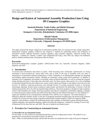
June 2013Rosemount 2120Dimensional drawings3/4 and 1-in. threaded mounting (standard length) . . . . . . . . . . . . . . . . . . . . . . . . . . . . . . page 133/4 and 1-in. thread mounting (extended length) . . . . . . . . . . . . . . . . . . . . . . . . . . . . . . . page 142-in. thread mounting . . . . . . . . . . . . . . . . . . . . . . . . . . . . . . . . . . . . . . . . . . . . . . . . . . . . page 15Flange mounting (standard length) . . . . . . . . . . . . . . . . . . . . . . . . . . . . . . . . . . . . . . . . . page 16Flange mounting (extended length) . . . . . . . . . . . . . . . . . . . . . . . . . . . . . . . . . . . . . . . . . page 17/ and 1-in. threaded mounting (standard length)3 4Note: Dimensions are in inches (millimeters)GLASS-FILLED NYLON HOUSINGALUMINUM/SST HOUSING3.5 (89)Allow 1.2 (30)To Remove LidAllow 1.2 (30)To Remove Lid4 (102)5(127)A4.7 (120)5.9(151)BCCD2.7(691.7(44)0.5 (13)Switchpoint (WhenMounted Horizontally)0.5 (13)Switchpoint (WhenMounted Vertically)2.7(69)D1.7(44)0.5 (13)Switchpoint (WhenMounted Horizontally)0.5 (13)Switchpoint (WhenMounted Vertically)NOTE: FOR HYGIENIC 2120 DIMENSIONS, SEE TYPE 1 DRAWING DOWNLOADS ON WEB SITEA. Cable Entry M20x1.5 or 1/2-in. NPTB. Cable Entry M20x1.5 or 3/4-in. NPTC. 1.6 (40) A/F HexagonD. 3/4-in. or 1-in. Threadwww.rosemount.com13
Rosemount 2120June 2013/ and 1-in. thread mounting (extended length)3 4Note: Dimensions are in inches (millimeters)GLASS-FILLED NYLON HOUSINGALUMINUM/SST HOUSING3.5 (90)Allow 1.2 (30)To Remove LidAllow 1.2 (30)To Remove Lid4 (102)5.9(151)A4.7 (120)B6.7(171)CCDDE(M)E(M)Ø1.1 (28) for 1-in. ThreadØ0.9 (23) for 3/4-in. Thread1.7(44)Ø1.1 (28) for 1-in. ThreadØ0.9 (23) for 3/4-in. Thread1.7(44)0.5 (13)Switchpoint (WhenMounted Horizontally)0.5 (13)Switchpoint (WhenMounted Vertically)0.5 (13)Switchpoint (WhenMounted Vertically)0.5 (13)Switchpoint (WhenMounted Horizontally)NOTE: FOR HYGIENIC 2120 DIMENSIONS, SEE TYPE 1 DRAWING DOWNLOADS ON WEB SITEA. Cable Entry M20x1.5 or 1/2-in. NPTB. Cable Entry M20x1.5 or 3/4-in. NPTC. 1.6 (40) A/F HexagonD. 3/4-in. or 1-in. ThreadTable 6. Fork length for 3/4 and 1-in. threaded 2120ProcessConnection3/4-in. Thread1-in. ThreadStandard LengthFork Length Code AMinimum LengthFork Length Code E (M)Maximum LengthFork Length Code E (M)(1)1.7 in. (44 mm)1.7 in. (44 mm)3.75 in. (95 mm)3.74 in. (94 mm)157.5 in. (4000 mm)157.5 in. (4000 mm)(1) Maximum extended length of fork with hand-polished option is 39.4 in. (1000 mm).14www.rosemount.com
June 2013Rosemount 21202-in. thread mountingNote: Dimensions are in inches (millimeters)GLASS-FILLED NYLON HOUSINGALUMINUM/SST HOUSING3.5 (90)Allow 1.2 (30)To Remove LidAllow 1.2 (30)To
Rosemount 2120 level switch ordering Table 1. 2120 ordering information The Standard offering represents the most common models and options. These options should be selected for best delivery. The Expanded offering is manufactured after receipt of order and is subject to additional delivery lead time. Model Product Description 2120 Vibrating .