Transcription
Proceedings of the 7th World Congress on Civil, Structural, and Environmental Engineering (CSEE'22)Lisbon, Portugal Virtual Conference – April 10 – 12, 2022Paper No. ICGRE 173DOI: 10.11159/icgre22.173Instrumented Bidirectional Load Test to 157000kN for Deep FoundationDesignAnil Cherian11Strainstall Middle East LLC (James Fisher and Sons plc, United Kingdom), Dubai, United Arab EmiratesEmail:anil@strainstall.aeAbstract - Accurate assessment of the soil-pile structure interaction and distribution of soil resistance along the shaft is complex andindispensable in any civil engineering construction project. The invention and use of the Bi-Directional Static Load Test (BDSLT), aself-balanced biaxial test method, for the high capacity static load testing of deep bored piles gives an innovative and powerful qualitycontrol tool to check the initial pile design. BDSLT is now becoming common practice around the Middle East and global constructionindustry, more convenient, economical, safe and accurate than traditional top-down loading tests. The specially designed, calibrated,sacrificial hydraulic jacks, can be installed at the tip or within the desired stratum at any elevation on the reinforcement cage of a boredpile. It offers the required static loading virtually to any high loads without any overhead load frame or other external reaction systems.An attempt has been made to check the initial pile design values and the results of subsequent BDSLT carriedout for a 2000mm diameterdeep foundation pile using bi-directional sacrificial jacks and Geokon embedded vibrating strain gauges to a test load of 157000kN atthe proposed mixed-use high-rise tower project in Dubai, United Arab Emirates. The results show that the test pile was capable ofsustaining ultimate shaft capacity due to the high shaft friction in the rock strata at a small settlement. This paper describes the installationand instrumentation of the pile, data analysis, and unambiguous information obtained, which can be directly applied to the permanentpile design procedure.Keywords: Bidirectional,Load test, Pile design, Skin friction, Settlement, Strain gauges1. IntroductionThe design of the pile foundation involves suitable assessment and optimization of key aspects of safety, serviceability,and cost. The United Arab Emirates, the construction hub of the Middle East, has been designing and implementing largescale high-rise building and infrastructure construction projects for the last three decades. The developments in contemporarygeotechnical foundation engineering make it possible to improve pile construction and testing practices. Most of ourGeotechnical designers, academic researchers, and consultants have many tools and data available to them, includingnumerous formulas, computer software, basic and sophisticated laboratory testing, and experience. Frequently, theseresources are used to estimate nominal pile parameters, to which a safety resistance factor is applied to determine anallowable pile capacity [1]. However, the advanced BDSLT method of high load testing provides an improved estimate ofshaft and bearing resistances to providing an economically viable design to reduce the geotechnical risk in the foundationindustry. BDSLT, a self-balanced test, loads the bored pile in compression using sacrificial jacks from the middle/bottomsection. As the hydraulic jack expands, the bottom side shear and tip resistance provide reaction for the upper side shear, andtop side shear provides reaction for the bottom segment of the pile. In the BDSLT method, side shear and tip resistancecomponents are measured separately [2].The application of bored shafts and their axial testing is increasing due to their excellence, economic efficiency, and tothe trend of high-rise and complex of structures. Foundation quality problems generated due to design flaws, concretestrength deficiency, improper construction due to less skilled workmanship and adverse weather conditions can be minimizedto a large extend by using the instrumented ultimate pile load test. Last three decades, the static loading test has advancedinto the bidirectional method of testing, which does provide the required information. BDSLT has become common toevaluate the geotechnical capacity of deep foundations, particularly bored and drilled foundations. The bidirectional staticload test (BDSLT) has been around since the early 1970s [3-4]. Subsequently, an independent development took place inBrazil [5], which led to an industrial production offered commercially in the Brazil piling industry. Later in the USA, the testwas carried out in full scale commercial use by hydraulic jack arrangement placed at or near the pile toe to pursue theICGRE 173-1
bidirectional technique now often referred to it as BDSLT [6-8]. Subsequently, this method was used in different parts of theworld to test the capacity of drilling shafts [9-10]. Schmertmann and Hayes have mentioned that bidirectional tests using OCell were first performed experimentally and commercially [11]. Poulos and Salem and Fellenius highlight the differentcharacteristics of the tests to help the building foundation industry [12-13]. This testing method was successfully used in thelast two decades for cost effective value engineering of foundation piles and barrettes in the Middle East Region [14-18 and1].The ultimate capacity of a deep foundation is often defined with reference to a pile head settlement. A widely useddefinition of the ultimate resistance of deep foundations installed in the ground is the load that would cause a deep foundationto settle by an amount equal to 10% of its diameter [19-20]. This method is internationally accepted and referred to in thedifferent standards [21-24].With an increase in demand for the high-rise building entities that utilize pile construction for their foundation design inDubai, it is evident that this study will play a key role in the current rapid infrastructure growth. Hence this paper articulatesthe initial pile design verification with the BDSLT result for the proposed high-rise tower on plot no. 336-210 and 336-299,Dubai, United Arab Emirates.2. Geological SettingsThe geology of the United Arab Emirates, and the Arabian Gulf area, have been substantially influenced bythe deposition of marine sediments associated with numerous sea-level changes during the relatively recentgeological time [25]. The Geology of the study area is characterized by the presence of the Barzaman Formation,which extends up to 23m depth. The Barzaman formations include reddish brown conglomerates, brecciateddolomitic calcisitites and breccia with clasts of coarse gravel and cobble size of limestone [26]. This formation isoverlaid by the reddish brown sandstones, which are extremely weak with localized medium beds of calcilutitebreccia. The sandstones are fine to medium sand size with a cementing material that imparts a very inconsistentstrength to the rock. The reddish brown sandstones are overlain by a brown to light brown Calcarenite. Localizedmedium beds of imperfectly laminated or massive Calcarenite with fine to medium clasts are also encountered[14]. Based on the borehole data (BH 01 to BH07), the design parameters (Unconfined Compressive Strength(UCS), Rock Quality Designation (RQD) with depth (m DMD – meter Dubai Municipality Datum) of the pilefoundations is summarized in Table 1. Unconfined compressive strength was applied to estimate the ultimate unitshaft resistance at each depth.Table 1: The general geotechnical parameters.Layer no.Description12Loose to medium dense silty SandVery weak to weak moderately fracturedSandstone/CalcareniteWeak to moderately weak moderately fracturedConglomerateVery weak to weak moderately fracturedSiltstone / CalcisiltiteWeak to moderately weak fractured Siltstone /Calcisiltite345Elevation(mDMD) 3.36 to -13.00-13.00 to -31.00UCS(MPa)0.9RQD(%)40-31.00 to -33.502.040-33.50 to -65.001.455-65.00 to -78.002.5453. MethodologyFull-scale BDSLT was performed for one instrumented deep bored concrete pile, viz. TP-1 (Test Pile) using eightsacrificial bidirectional hydraulic jacks embedded between upper and lower steel bearing plates within the pile foundationelement (Table 2 and Fig.1). When required hydraulic pressure is applied during testing, the jack assembly can expand inICGRE 173-2
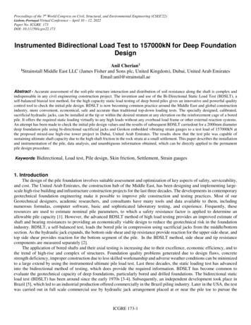
both directions, and loads are applied to the pile in an upward and downward direction. Hydraulic jack positioning isdetermined based on the geotechnical parameters. This is used as a basis to compute the expected skin friction and endbearing capacities of the piles. The main purpose of positioning the jack assembly precisely will be to equalize the bidirectional forces in the pile. This will avoid the premature failure of piles in one direction and thereby complete the fullscale load test. This requires not only the knowledge of geotechnical parameters but also the native experience gained fromvarious similar projects. From the initial geotechnical report, unconfined compressive strength (UCS) of a borehole near topile load test is extracted and the unit shaft friction (kN – kilo Newton) is calculated. From unit shaft friction obtained, thetotal shaft friction of the pile is calculated and the mid-value of the shaft friction is used as the position of the hydraulic cellassembly [16].Table 2: Test pile details.Pile TypePile Diameter(mm)Cut offLevel (mDMD)Toe Level(mDMD)Workingload (kN)Test load(kN)628001570002000-13.09-78.00Strain gauge level -13.60, -17.20, -20.80, -24.40, -28.00, -31.60, -35.20, -38.80, -42.40, -46.00, -49.60,-53.20, -59.80, -62.30, -64.80, -67.30, -69.80, -72.30, -74.80, -77.50 and jack level at (m DMD)56.50TP – 1The instrumentation of the pile includes twenty levels of Geokon vibrating wire concrete embedded strain gauges,hydraulics jacks, tell-tale rod extensometers in conjunction with displacement transducers. Vibrating wire strain gaugesembedded at different depths are to measure strain during load application, and to calculate the shaft friction and loaddistribution. Tell-tales extensometers as well as displacement transducers measure displacement at cell top and cell bottom.Pile top movement under an applied load will be measured directly from the shaft top using two displacement transducersthat are installed at the testing platform level (Fig.1 and Fig. 2). Once the required concrete strength is attained, generally 14days after casting or as per the specification, the pile test will be started. During the application of load, the hydraulic cellbegins working in the opposite direction, upward against upper skin friction and downward against lower skin friction andbase resistance. The test is considered to be complete after reaching the ultimate capacity above or below the hydraulic cellor upon reaching the maximum capacity of the hydraulic cells. The load increments were applied as specified in the loadingschedule and each successive load increment was held constant by adjusting the hydraulic jack pressure until the settlementcriteria were met. Data acquisition of all embedded instruments was connected to a data logger and a laptop allowing thedata to be recorded and stored automatically at stipulated intervals and displayed in real-time. The unit shaft resistanceobtained from the load test results was compared with the initial ground test parameters using Eurocode 7 [27] proceduresto understand the soil-pile interaction process.ICGRE 173-3
Fig. 1: BDSLT pile installation.Fig.2: BDSLT test setup.ICGRE 173-4
4. Results and Discussion4.1. Settlement and shaft frictionThe bidirectional load displacement data obtained from the pile test is analysed to obtain the required Equivalent TopLoading Curve (ETL). The ETL curve (Fig. 3) is an assessment of the applied load-displacement performance of the test pilewhich would result from a traditional top-loading static compression test. Since bi-directional test loads are applied at somedepth within the foundation element, such load-displacement relationships are not measured but must be constructed usingthe assumptions [8]. BDSLT site data are typically presented in a butterfly-shaped plot giving load-displacement behaviourof the pile in both directions, governed by upper shaft, lower shaft and base resistances developed during the test. The jackmovement data obtained from the test is analysed using an equivalent top loading method to identify the elastic settlementcurve [28-29]. The equivalent top load curve is constructed by selecting a displacement value from the tests data. Thisselected value will be used for both the top and bottom cells because the pile is assumed to be rigid. To obtain the load forboth up and down curves, draw a line from the selected value until it meets the load displacement curve. Add thecorresponding loads to obtain the total load which is equivalent to the load on the pile head. Continue the procedures toconstruct the equivalent top-load curve and modify the curve by including the elastic shortening of the pile foundation [8].Fig. 3: Settlement values obtained from BDSLT.The settlement values (Fig 3) obtained during the test at working load were 17.60mm and the ultimate load was 38.60mmrespectively. The increase of settlement values in the ultimate load is perhaps due to the soil types, varying density, andimplies that the load-carrying capacity is dominated by shaft resistance. It is difficult to estimate the possible differentialsettlement undergoing various loading forces after the completion of the superstructure [30]. The inferences of settlementfrom the pile load test data may be conservative, although it must be noted that the general foundation settlement behaviouris dependent on the individual pile characteristics as well as the ground conditions within the zone of influence of theICGRE 173-5
structure. Therefore, during the design of this foundation, the side resistance of the pile was the only capacity criterionaccounted for in the overall design, and the settlement value was not considered. The mobilized shaft friction obtained duringthe test from strain gauge readings at the ultimate load and ground test is presented in Table 3.Table 3: Mobilized unit shaft friction from load test and ground test.Strain gauge level(from pile top tobottom)1 to 22 to 33 to 44 to 55 to 66 to 77 to 88 to 99 to 1010 to 1111 to 1212 to Jack13 to Jack13 to 1414 to 1515 to 1616 to 1717 to 1818 to 1919 to 20StratumLoose to medium dense silty SandVery weak to weak moderatelyfractured Sandstone/CalcareniteWeak to moderately weakmoderately fractured ConglomerateVery weak to weak moderatelyfractured Siltstone / CalcisiltiteWeak to moderately weak fracturedSiltstone / CalcisiltiteLoad test (at 157000 332936340GroundtestkPa2373532963954.2. Load transfer mechanismThe pile-element relation is called the load-transfer function (t - z curve), which is a mathematical expression of theload and movement relation [31]. All load-transfer functions are curves that either rises steeply at first and become less steepas the movement increases or reduce after having reached a peak at a certain movement. Occasionally, a shaft resistanceseems constant after having reached a maximum value and thus demonstrating a plastic response. Nevertheless, the loadmovement behavior to shaft resistance along with a pile segment, after an initial movement, is only rarely plastic [31].The axial pile performance of deep foundation was analyzed using the relationship between mobilized soil- pile sheartransfer and pile vertical deflection/settlement (t-z curve) of the bored pile during stages of loading. There are numerousdifferent methods for interpreting this kind of axial load transfer and pile displacement curves [32]. The most commonapproach is by demonstrating the mobilization of shaft friction displayed as a set of springs distributed along the pile shaft,and the axial elastic stiffness of the pile [33]. The distribution of stiffness of both the pile and soil, pile geometry, and soildistribution are all influential factors. The construction of t-z analysis, by using the unit resistance values based on strainICGRE 173-6
gauge data and settlement from the BDSLT data, describes the soil-pile behavior over the entire length of the pile. In orderto estimate the load transfer mechanism, calculations of the pile settlement can be performed using the pile settlement as afunction of unit shaft friction. The plot obtained for the test pile is given in Fig.4.Fig.4: Skin friction – settlement (t-z) plot from load testThe maximum average unit skin resistance mobilized from the pile load test to 1193 kPa and at a normalized pilesettlement of 38.60mm (Fig 4). The unit shaft friction kept increasing linearly and not reached its maximum stress, even atthe ultimate test load. Based on the t-z curve, it is suggested that plastic deformation did not reach along the pile shaft atdifferent loads. It can be due to the fact that the majority of the load is consumed by the deeper stiff layers. This behaviourcan be a result of a stiff pile and partly dependent on a minor pile settlement as observed from the load tests. This indicatesthat the test piles are not fully mobilized and the settlement is within the general permissible limit of less than 2% of the pilediameter at the working load [16, 34].The t-z functions analysis of the results of the load test enables the settlement of the foundation supported on the pile tobe determined. This ultimately eliminates the need for a theoretical assessment of capacity and applying some factor of safetyto arrive at a presumed safe working load that may or may not give an acceptable level of settlement, which are removedfrom the test result that the pile toe resistance is very small. The load-distribution analysis will enable an estimate on thelong-term settlement behaviour of a foundation supported on a similar pile for which the analysis of the pile response wouldhave to include the effect of adjacent foundation and other related influencing factors [35]. Moreover, the analysis will aidin the sectioning and execution of a suitable length and diameter and excavation around the piles or back-filling to the site,etc. In order to assess the performance of the test piles further and to derive suitable shaft friction design values, optimizationof pile design was carriedout using Eurocode 7 procedure before execution of production piles of the project.ICGRE 173-7
4.3.Design shaft resistanceThe introduction of Eurocode in the foundation testing allows for the application of modern unified technological toolsfor the design of structures and different combinations of loads with the application of all types of construction materials. Itapplies the principles of ultimate limit states for analysis of shaft bearing capacity, which is, factoring resistances and loadsseparately [36]. In this study, the shaft capacity of a single pile that is subjected to compression is calculated using Eurocode7. Eurocode harmonises the geotechnical design with structural design through the introduction of a common design methodand provide a flexible code through the introduction of different design approaches to use partial material factors or partialresistance factors, and therefore can be applied to different national and international design practices.Eurocode 7 describes the procedures for obtaining the characteristic compressive resistance of a pile [37]:a) Directly from the load testb) By calculation from profiles of ground test results from the soil reportThe design pile resistances derivation requires applying the resistance partial factors to the characteristic values. Sinceonly one test was carried out, the obtained unit shaft friction parameters from a maximum load of 250% have been consideredin the evaluations and a correlation factor of ξ1 1.3. The combinations of partial factor values that should be used for DesignApproach I are as follows:DAI.CI: A1 M1 R1DAI.C2: A2 M1 or M2 R4The combinations of sets of partial factor values that ought to be used for Design Approach 2DA2: A1 M1 R2Whereas Design Approach 3 is computed as:DA3: A1 M2 R3are as follows:where:A1/A2 denotes partial factors on action.M1/M2 denotes partial factors for soil parameters.R1/R2/R3/R4 denotes partial factors for resistance.Characteristic resistance obtained using a partial factor of 1.30 was calculated based on shaft friction within the rocklayers of the pile embedded. Based on the results obtained from the load test and the ground result, the recommended designshaft friction values are calculated by subtracting half of the standard deviation from the average value of the load test andground test results (Table 4).Table 4: Adopted design unit shaft friction after BDSLTLoad test (at 157000kN)Strain gauge level(from top to bottom)Stratum1 to 2Loose to medium dense siltySandkPa2 to 33 to 4RecommendedvaluekPa578ICGRE 173-8Groundtest basedEurocodekPa18294
4 to 55 to 66 to 77 to 88 to 99 to 1010 to 1111 to 1212 to Jack13 to Jack13 to 1414 to 1515 to 1616 to 1717 to 1818 to 1919 to 20Very weak to weakmoderately fracturedSandstone/CalcareniteWeak to moderately weakmoderately fracturedConglomerateVery weak to weakmoderately fracturedSiltstone / CalcisiltiteWeak to moderately weakfractured Siltstone 4107332936340271296227262304318The initial test pile was mainly performed prior to the installation of the production piles to check the pile capacity,construction quality and the performance of the foundations. A linear increase of unit skin friction values was observed anddoes not display evidence of developing geotechnical failure, giving a comfortable margin of safety. This indicates that thepile can be still loaded to mobilize ultimate skin friction resistance along the complete shaft length without any geotechnicalrisk. The shaft friction obtained from the load test was more than adequate to resist loads in excess of the pile working loadand hence not able to mobilize any tip resistance. Since the skin friction in the upper and lower part of the shaft segmentdoes not seem to have been fully mobilized during a load test, it was proposed that the ground test data in that location beused during the final design. The results of the preliminary pile load testing program were compared with those obtainedfrom the ground test. It can be concluded that the load test can appropriately represent the characteristics of soil strata andthe side resistances determined are larger than the design values adopted. On the basis of load test data, recommended unitskin friction values were used for the final design of production piles.Table 5: Revised pile design used in the projectPile IDDiameter (mm)Cutoff level (m)Toe level (m)Pile capacity (kN)TP-12000-13.09-57.89566694Based on the above result, for a compression load of 66694 kN for the piles with a length of 51.91m is found to besufficient for the foundation design. Accordingly, the piles were redesigned with a length reduction of 20% and wereimplemented in the project (Table 5). BDSLT results and subsequent analysis reconfirmed the pile length reduction of 13.0mto provide a suitable value engineering design by saving in foundation costs by reducing drilling costs, material costs,ICGRE 173-9
construction time, labor and less expensive to load test. The results obtained from the load test were accurate as there wasno indication of pile defects due to poor construction and quality control.5. Conclusions and suggested future researchThe effective performance of this full-scale instrumented load test provides the confirmation of soil characteristics andthe pile-soil interaction for a reliable and economical foundation design. Load test results indicate that the pile design can beoptimized in length up to 20%, reducing the current pile length from 64.91m to 51.91m deep. This study has proven thatinstrumented BDSLT method can be effectively performed in any part of the world to provide a quality control tool of thedesign resistance parameters. The results derived from the testing have to lead to a reassessment of the original pile designto benefit future stakeholders in designing economically viable high-rise building projects by changing the pile geometry.The results of this instrumented BDSLT on a large bored pile emphasized the necessity of using preliminary load tests forefficient design and an excellent model for such prestigious future high-rise building projects in the region. Further studieson similar high capacity fully instrumented BDSLT in different geotechnical conditions will be a reliable, cost-effective toolto improve confidence in the deep foundation design.AcknowledgementThe author is grateful to Strainstall Middle East LLC (James Fisher and Sons plc, United Kingdom), Dubai, United ArabEmirates for their continued support and encouragement.References[1] A. Cherian, “Geotechnical evaluation of multi-layered Simsima Limestone using Bidirectional Static load test,” J. Geo.Soc Ind., vol.97,pp.670-674, 2021a.[2] J.H.Schmertmann, J.A.Hayes, A. John , M. Thomas and J.O. Osterberg, “O-Cell testing case histories demonstrate theimportance of bored pile (drilled shaft) construction technique,” in Proceedings of the fourth international conferenceon case histories. Missouri,1998.[3] G.L.Gibson and D.W. Devenny, “Concrete to bedrock testing by jacking from the bottom of a borehole,” Can. GeotechJ., 10, pp. 304-306, 1973.[4] J.M.Amir, “Interpretation of load tests on piles in rock,” in Proceedings of the 7th Asian Regional Conference on SoilMechanics and Foundation Engineering, Haifa, 1983, pp 235-238.[5] P.C.A.Elisio, “Celula Expansiva Hidrodinamica – Uma nova maneira de executar provas de carga (Hydrodynamicexpansive cell. A new way to perform loading tests) ,” Independent publisher, Belo Horizonte, Minas Gerais State,Brazil, 1983.[6] J.O.Osterberg, “A New Simplified Method for Load Testing Drilled Shafts,” Foun Drill Vol. XXIII ADSC, p 9, 1984.[7] J.O.Osterberg, “New Load Cell Testing Device,” in Proceedings of the 14th Annual Conference. Deep FoundationsInstitute, pp. 17 – 28, 1989.[8] J.O.Osterberg, “The Osterberg load test method for bored and driven piles- The first ten year,” in Proceedings of theSeventh International Conference and Exhibition on Piling and Deep Foundations, Vienna, Austria, 1989.[9] J.W.Goodwin, “Bi-Directional Load Testing of Shafts to 6000 Tons,” Am. Soc. of Civil. Eng. (ASCE) Geot Sp Publ,vol.58, p 204, 1993.[10] B.J.Meyer and P.R.Shade, “Touchdown for the O-cell Test,” Civil. Eng. Vol.65, 45-57, 1995.[11] J.H.Schmertmann and J.A.Hayes, “The Osterberg cell and bored pile testing – a symbiosis,” Proceedings, 3rd IGEC,Cairo, Egypt,1997.[12] H.G.Poulos, “Tall building foundations: design methods and applications,” Innov Infra Solu., vol.1, pp.1-51, 2016.[13] H.Salem and B.H. Fellenius, “Bidirectional pile testing - what to expect,” in Proceedings of the 70th Annual CanadianGeotechnical Conference, Ottawa, 2017.[14] A.Cherian, “Value engineering of foundation design using Bidirectional Static Load Test (BDSLT): A Case Studyfrom Dubai, United Arab Emirates,” Int Jour Ear Sci and Eng., vol.11 pp.270-273, 2018.ICGRE 173-10
[15]A. Cherian, “ Geotechnical and geological aspects of Structural Health Monitoring in high-rise buildings ,” J IndGeoph Union, vol.24, pp. 10-24 . 2020a.[16] A.Cherian, “Assessment of pile capacity using Bidirectional Static Load Test (BDSLT) ,” Ind Geot J ., vol. 51, pp.369375, 2020b.[17] A. Cherian , “Characterization of Simsima Limestone for foundation design in Qatar: A Case Study J Rock Mech TunTech ,” vol.26 pp.109-122, 2020c.[18] A.Cherian, “Bidirectional Static load test using instrumented pile: An innovative testing method in the constructionindustry,” in Proceedings of the 7th, ICRAGEE (Seismic Design and Performance), India, pp. 361-364 , 2021b.[19] British Standards Institution, “Code of practice for foundations,” BS8004, London, 1986.[20] R.Salgado R, “The engineering of foundation,” 1st Ed. McGraw-Hill, New York, 2008.[21] ASTM D8169, “Standard test methods for deep foundations under Bi-Directional Static Axial Compressive Load,”ASTM International, USA, 2018.[22] ICE, “Manual of Geotechnical Engineering,” 1458-1460, 2012.[23] Federation of Piling Specialists, “Handbook on pile load testing. Federation of Piling Specialists,” Beckenham,2006.[24] IRC 78, “Standard specifications and code of practice for road bridges, Section VII Parts 1 and 2, Foundations andSubstructure,” 2014.[25] H.G.Poulos, “A review of geological and geotechnical features of some Middle Eastern countries,” Inn Infra Sol.,vol.3, pp.45-58, 2018.[26] S.Macklin and A. Gaba “Engineering in the Barzaman Formation, Coastal Dubai, UAE,” Civil Eng J., vol.162, pp.18-24, 2009.[27] Eurocode 7, “Geotechnical design: The European Union Report no. EUR 26227 EN doi: 10.2788/3398,” 2013.[28] M.England, “Review of methods of analysis of test results from bi- directional static load tests,” in Proceedings of DeepFoundations on Bored and Auger Piles, Taylor & Francis, pp 235–239, 2009.[29] S.Hoyoung, B.M.Rozbeh and D.L. William, “Assessment of methods for construction of an equivalent top loading curvefrom O-cell test data,” Soil and Found, vol. 56, pp. 889–903, 2016.[30] A. Mandolini, G.Russo, G and C.Viggiani, “Pile foundations: Experimental investigations, analysis and design,”Ground. Eng., vol.38(9), pp.34-35, 2005.[31] B.H.Fellenius and M.M. Rahman, “Load-movement Response by t-z and q-z Functions,” Geot Eng J SEAGS andAGSSEA, vol. 50 pp.11-19, 2019.[32] The American Petroleum Institute, “Recommended Practice for Planning, Designing and Constructing Fixed OffshorePlatforms,” 22nd Ed. Washington DC, USA, 2007.[33] K.Karlsrud, “Ultimate shaft friction and load-displacement response of axially loaded piles in clay based on instrum
Strain gauge level (m DMD) -13.60, -17.20, -20.80, -24.40, -28.00, -31.60, -35.20, -38.80, -42.40, -46.00, -49.60, . 56.50 . The instrumentation of the pile includes twenty levels of Geokon vibrating wire concrete embedded strain gauges, hydraulics jacks, tell-tale rod extensometers in conjunction with displacement transducers. Vibrating wire .