Transcription
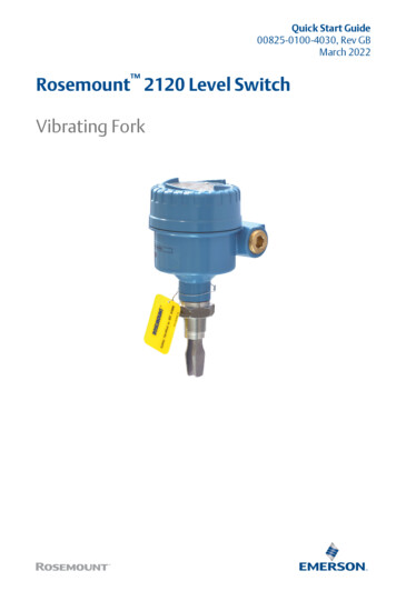
Quick Start Guide00825-0100-4030, Rev GBMarch 2022Rosemount 2120 Level SwitchVibrating Fork
Quick Start GuideMarch 2022ContentsAbout this guide.3Installation. 5Prepare the electrical connections.11Connect wiring and power up.26Configuration.30Operation.322Rosemount 2120 Level Switch
March 20221Quick Start GuideAbout this guideThis Quick Start Guide provides basic guidelines for the Rosemount 2120.Refer to the Rosemount 2120 Reference Manual for more instructions. Themanual and this guide are also available electronically atEmerson.com/Rosemount.1.1Safety messagesWARNINGFailure to follow safe installation and servicing guidelines could result indeath or serious injury.Ensure the level switch is installed by qualified personnel and in accordancewith applicable code of practice.Use the level switch only as specified in this manual. Failure to do so mayimpair the protection provided by the level switch.The weight of a level switch with a heavy flange and extended fork lengthmay exceed 37 lb. (18 kg). A risk assessment is required before carrying,lifting, and installing the level switch.Repair, e.g. substitution of components, etc. may jeopardize safety and isunder no circumstances allowed.WARNINGExplosions could result in death or serious injury.Verify the operating atmosphere of the level switch is consistent with theappropriate hazardous locations certifications.Before connecting a handheld communicator in an explosive atmosphere,ensure the instruments are installed in accordance with intrinsically safe ornon-incendive field wiring practices.In explosion-proof/flameproof and non-incendive installations, do notremove the housing cover when power is applied to the level switch.The housing cover must be fully engaged to meet flameproof/explosionproof requirements.Quick Start Guide3
Quick Start GuideMarch 2022WARNINGElectrical shock could cause death or serious injury.Avoid contact with the leads and terminals. High voltage that may bepresent on leads can cause electrical shock.Ensure the power to the level switch is off, and the lines to any other externalpower source are disconnected or not powered while wiring the level switch.Ensure the wiring is suitable for the electrical current and the insulation issuitable for the voltage, temperature, and environment.WARNINGProcess leaks could result in death or serious injury.Ensure the level switch is handled carefully. If the process seal is damaged,gas might escape from the vessel (tank) or pipe.WARNINGPhysical accessUnauthorized personnel may potentially cause significant damage to and/ormisconfiguration of end users’ equipment. This could be intentional orunintentional and needs to be protected against.Physical security is an important part of any security program andfundamental to protecting your system. Restrict physical access byunauthorized personnel to protect end users’ assets. This is true for allsystems used within the facility.CAUTIONHot surfacesThe flange and process seal may be hot at high process temperatures. Allowto cool before servicing.4Rosemount 2120 Level Switch
March 2022Quick Start Guide2Installation2.1Fork alignment in a pipe installationThe fork is correctly aligned by positioning the groove or notch as indicated(Figure 2-1).Figure 2-1: Correct Fork Alignment for Pipe InstallationABOKABOKA. Tri Clamp process connections have a circular notchB. Threaded process connections have a groove2.2Fork alignment in a vessel (tank) installationThe fork is correctly aligned by positioning the groove or notch as indicated(Figure 2-2).Figure 2-2: Correct Fork Alignment for Vessel (Tank) InstallationABCOKOKOKA. Tri Clamp process connections have a circular notchB. Threaded process connections have a grooveC. Flanged process connections have a circular notchQuick Start Guide5
Quick Start GuideMarch 20222.3Mounting the threaded version2.3.1Threaded vessel (tank) or pipework connectionProcedure1. Seal and protect the threads. Use anti-seize paste or PTFE tapeaccording to site procedures.A gasket may be used as a sealant for BSPP (G) threaded connections.2. Screw the level switch into the process connection.NoteTighten using the hexagon nut only.Figure 2-3: Vertical InstallationAA. Gasket for BSPP (G) threaded connectionFigure 2-4: Horizontal InstallationAA. Gasket for BSPP (G) threaded connection6Rosemount 2120 Level Switch
March 20222.3.2Quick Start GuideThreaded flange connectionProcedure1. Place the customer-supplied flange and gasket on the vessel (tank)nozzle.AA. Gasket (customer supplied)2. Tighten the bolts and nuts with sufficient torque for the flange andgasket.3. Seal and protect the threads. Use anti-seize paste or PTFE tapeaccording to site procedures.A gasket may be used as a sealant for BSPP (G) threaded connections.Quick Start Guide7
Quick Start GuideMarch 20224. Screw the level switch into the flange thread.NoteTighten using the hexagon nut only.AA. Gasket for BSPP (G) threaded connection2.4Mounting the flanged versionProcedure1. Lower the level switch into the nozzle.AA. Gasket (customer supplied)8Rosemount 2120 Level Switch
March 2022Quick Start Guide2. Tighten the bolts and nuts with sufficient torque for the flange andgasket.2.5Mounting the Tri Clamp versionProcedure1. Lower the level switch into the flange face.AA. Seal (supplied with Tri Clamp)Quick Start Guide9
Quick Start GuideMarch 20222. Fit the Tri Clamp.10Rosemount 2120 Level Switch
March 20223Prepare the electrical connections3.1Cable selectionQuick Start GuideUse 26–14 AWG (0.13 to 2.5 mm2) AWG wiring. Twisted-pairs and shieldedwiring is recommended for environments with high EMI (electromagneticinterference). Two wires can be safely connected to each terminal screw.3.2Cable glands/conduitsFor intrinsically safe, explosion-proof/flameproof, and dust-proofinstallations, only use certified cable glands or conduit entry devices.Ordinary location installations can use suitably rated cable glands or conduitentry devices to maintain the Ingress Protection (IP) rating.Unused conduit entries must always be sealed with a suitably ratedblanking/stopping plug.NoteDo not run signal wiring in conduit or open trays with power wiring or nearheavy electrical equipment.3.3Power supplyThe power supply requirements are dependent on the electronics selected. Direct load switching: 20 - 60 Vdc or 20 - 264 Vac (50/60 Hz) PNP/PLC electronics: 20 - 60 Vdc Relay DPCO (Double Pole Changeover) electronics (standard):20 - 60 Vdc or 20 - 264 Vac (50/60 Hz) Relay DPCO electronics (12 Vdc nominal): 9 - 30 Vdc NAMUR electronics: 8 Vdc 8/16 mA electronics: 24 Vdc3.4Hazardous areasWhen the device is installed in hazardous areas (classified locations), localregulations and the conditions-of-use specified in applicable certificatesmust be observed. Review the Rosemount 2120 Product Certificationsdocument for information.Quick Start Guide11
Quick Start Guide3.5March 2022Wiring diagramsCAUTION Before use, check the cable glands and blanking plugs are suitably rated. Isolate supply before connecting the switch or removing the electronics. The Protective Earth (PE)earthing system.12terminal must be connected to an externalRosemount 2120 Level Switch
March 20223.5.1Quick Start GuideDirect load switching cassetteFigure 3-1: Direct Load Switching (2-wire) Cassette (Red Label) – Code T123RFuse 2A(T)DPSTILNL0V VR External load (must be fitted)N NeutralL LiveNoteA DPST (Double Pole, Single Throw) on/off switch must be fitted for safedisconnection of the power supply. Fit the DPST switch as near as possible tothe level switch. Keep the DPST switch free of obstructions. Label the DPSTswitch to indicate it is the supply disconnection device for the level switch.Table 3-1: Electrical ParametersParameterValueU20 - 60 Vdc or 20 - 264 Vac (50/60 Hz)IOFF 4 mAIL20 - 500 mAIPK5 A, 40 ms (inrush)Quick Start Guide13
Quick Start GuideMarch 2022Table 3-2: Direct Load FunctionsMode: dry on, high level alarm132IL1U12 VR321ILFILRL VLED on continuouslyF32 4 mAN0VL VLED flashes everysecond1U12 VRDPSTDPSTN0VMode: wet on, low level alarm32 4 mAILFRDPSTDPSTN0VN0VL VLED on continuouslyFL VLED flashes everysecond Load on Load off14Rosemount 2120 Level Switch
March 20223.5.2Quick Start GuidePNP/PLC cassetteFigure 3-2: PNP/PLC (3-wire) Cassette (Yellow Label) – Code GWet On Mode1234F V O/P 0VF Fuse 2A(T)Table 3-3: Electrical ParametersParameterValueU20 - 60 VdcI 4 mA ILI L (OFF) 100 μAIL(MAX)0 - 500 mAIPK5 A, 40 ms (inrush)UOUT(ON)U - 2.5 Vdc (20 C)U - 2.75 Vdc (-40 to 80 C)Quick Start Guide15
Quick Start GuideMarch 2022Table 3-4: PNP/PLC Cassette FunctionsMode: dry on, high level alarmMode: wet on, low level alarmPLC (positive input)1234123U 3V 412IL 3VIL-I/P PLC34123U 100 μA-I/P PLC4 100 μAILIL-I/P PLC-I/PPLCPNP dc12341234123U1234U 3V 3VRRFFIL 4 FFIL 100 μA-RRIL- IL 100 μA- -LEDLED on continuously16LED flashes everysecondLED on continuouslyLED flashes everysecondRosemount 2120 Level Switch
March 20223.5.3Quick Start GuideRelay DPCO cassette (standard version)Figure 3-3: Relay DPCO Cassette, Standard Version (Green Label) – CodeV123Fuse 0.5 (T)456789NCCNONCCNODPSTNL0V VNoteA DPST (Double Pole, Single Throw) on/off switch must be fitted for safedisconnection of the power supply. Fit the DPST switch as near as possible tothe level switch. Keep the DPST switch free of obstructions. Label the DPSTswitch to indicate it is the supply disconnection device for the level switch.Table 3-5: Electrical ParametersParameterValueU20 - 60 Vdc or 20 - 264 Vac (50/60Hz)I 6 mAQuick Start Guide17
Quick Start GuideMarch 2022Table 3-6: NC, C, and NO TerminalsParameterResistive loadInductive loadcos ϕ10.4L/R0 ms7 msIMAX5A3.5 Aac250 V250 Vdc30 V30 Vac1250 VA875 VAdc240 W170 WUMAXPMAXTable 3-7: Relay Cassette FunctionsMode: dry on, high level alarmNC C NONC C NOLED on continuously18NC C NONC C NOLED flashes everysecondMode: wet on, low level alarmNC C NONC C NOLED on continuouslyNC C NONC C NOLED flashes everysecondRosemount 2120 Level Switch
March 20223.5.4Quick Start GuideRelay DPCO cassette (12 Vdc nominal version)Figure 3-4: Relay DPCO Cassette, 12 Vdc Nominal Version (Green Label)– Code EFuse 0.5 (T)NCCNONCCNODPST0V VNoteA DPST (Double Pole, Single Throw) on/off switch must be fitted for safedisconnection of the power supply. Fit the DPST switch as near as possible tothe Rosemount 2120. Keep the DPST switch free of obstructions. Label theDPST switch to indicate it is the supply disconnection device for theRosemount 2120.Table 3-8: Electrical ParametersParameterValueU9 - 30 VdcI 4 mATable 3-9: NC, C, and NO TerminalsParameterResistive loadInductive loadcos ϕ10.4L/R0 ms7 msIMAX2A1AUMAX30 V30 VPMAX60 W30 WQuick Start Guide19
Quick Start GuideMarch 2022Table 3-10: Relay Cassette FunctionsMode: dry on, high level alarmNC C NONC C NOLED on continuously20NC C NONC C NOLED flashes everysecondMode: wet on, low level alarmNC C NONC C NOLED on continuouslyNC C NONC C NOLED flashes everysecondRosemount 2120 Level Switch
March 20223.5.5Quick Start GuideNAMUR cassetteFigure 3-5: NAMUR Cassette (Light Blue Label) – Code K- AA. A certified intrinsically safe isolating amplifier to IEC 60947-5-6Note This cassette is suitable for Intrinsically Safe (IS) applications and requiresa certified isolating barrier. See the Rosemount 2120 ProductCertifications document for Intrinsically Safe approvals. This electronics cassette is also suitable for non-hazardous (safe) areaapplications. It can only be interchanged with the 8/16 mA cassette. Do not exceed 8 Vdc.Table 3-11: Electrical ParametersParameterValueION2.2 - 2.5 mAIOFF0.8 - 1.0 mAIFAULT 1.0 mAQuick Start Guide21
Quick Start GuideMarch 2022Table 3-12: NAMUR Cassette FunctionsMode: dry on, high level alarmMode: wet on, low level alarm(-)1(-)1( )2(-)1( )2( )2(-)1( )2 2.2 mA 1.0 mA 2.2 mA 1.0 mALED on continuouslyLED flashes everysecondLED on continuouslyLED flashes everysecond22Rosemount 2120 Level Switch
March 20223.5.6Quick Start Guide8/16 mA cassetteFigure 3-6: 8/16 mA Cassette (Dark Blue Label) – Code H123- AA. A certified intrinsically safe isolating amplifier to IEC 60947-5-6Note This cassette is suitable for Intrinsically Safe (IS) applications and requiresa certified isolating barrier. See the Rosemount 2120 ProductCertifications document for Intrinsically Safe approvals. This electronics cassette is also suitable for non-hazardous (safe) areaapplications. In this case, U 11 - 36 Vdc. It can only be interchanged with a NAMUR cassette.Table 3-13: Electrical ParametersParameterValueU24 Vdc NominalION15 - 17 mAIOFF7.5 - 8.5 mAIFAULT 3.7 mAQuick Start Guide23
Quick Start GuideMarch 2022Table 3-14: 8/16 mA Cassette FunctionsMode: dry on, high level alarm1(-)( )23 15 mALED on continuously241Mode: wet on, low level alarm(-)( )23 8.5 mALED flashes everysecond1(-)( )231 15 mA(-)( )23 8.5 mALED on continuouslyLED flashes everysecondRosemount 2120 Level Switch
March 20223.6Quick Start GuideGroundingMake sure grounding is done according to national and local electricalcodes. Failure to do so may impair the protection provided by theequipment.3.6.1Signal cable shield groundingMake sure the instrument cable shield is: Trimmed close and insulated from touching the housing. Continuously connected throughout the segment. Connected to a good earth ground at the power supply end.Figure 3-7: Signal Cable Shield Grounding at Power Supply EndBBDA.B.C.D.3.6.2CCATrim shield and insulateMinimize distanceTrim shieldConnect shield back to the power supply groundGrounding the housingThe most effective grounding method for the metal housing is a directconnection to earth ground with minimal impedance. Housings with NPTconduit entries do not have an earth ground point and must use the forkearth.Figure 3-8: Ground ScrewsAA. External ground screwQuick Start Guide25
Quick Start Guide4March 2022Connect wiring and power upProcedure1.Verify the power supply is disconnected.2. Remove the field terminals cover.In an explosion-proof/flameproof installation, do not remove thelevel switch cover when power is applied to the unit. The cover mustalso not to be removed in extreme environmental conditions. Versions of the Rosemount 2120 with a metal housing areexplosion-proof/flameproof. They have a cover-lock to beundone first. Versions of the Rosemount 2120 with a glass-filled-nylon housingare not explosion-proof/flameproof. They do not have a coverlock.3. Remove the plastic plugs.Versions of the Rosemount 2120 with a glass-filled-nylon housing donot have plastic plugs fitted.26Rosemount 2120 Level Switch
March 2022Quick Start Guide4. Pull cables through the cable gland/conduits. Cassettes with a single terminal only require one cable.Identification of thread size and type:M20 x 1.5¾-in. ANPTM20M20 x 1.5¾-in. ANPTM20 Cassettes with two or more terminals may require more than onecable.5. Connect the cable wires (see Wiring diagrams for other cassettes).Metal housing:Glass-filled-nylon housing:6. Ensure proper grounding.Quick Start Guide27
Quick Start GuideMarch 20227. Tighten the cable glands.Apply PTFE tape or other sealant to the threads.Metal housing:Glass-filled-nylon housing:NoteMake sure to arrange the wiring with a drip loop.28Rosemount 2120 Level Switch
March 2022Quick Start Guide8. Plug and seal the unused conduit connection to avoid moisture anddust accumulation inside the housing.Apply PTFE tape or other sealant to the threads.Metal housing:Glass-filled-nylon housing:9. Attach and tighten the cover.Make sure the cover is fully engaged.10.Required for explosion-proof/flameproof installations only:The cover must be fully engaged to comply with explosion-proofrequirements.11. Re-lock the cover.12. Connect the power supply.Quick Start Guide29
Quick Start GuideMarch 20225Configuration5.1Output mode and time delayAll electronics cassettes have a rotating switch for setting the output to be"Dry On" (on when the fork is sufficiently dry) or "Wet On" (on when the forkis sufficiently wet).The electronics uses hysteresis to help prevent constant switching of theoutput from dry-to-wet and wet-to-dry states due to splashing orintermediate conditions. To further prevent false switching, the rotatingswitch also sets a time delay of up to 30 seconds before the output changes.A small cut-out in the rotating switch indicates the present mode and timedelay.Figure 5-1: Top-down View: Example Cassette Inside HousingABPLC/PNPOPERATION MODE OUT-Dry On ModeDryWetDryWet1234Wet On ModeDry On0.31Wet On0.313310103030Isolate SupplyBefore RemovingSeconds DelayA. 'Heartbeat' LEDB. Rotating switch for setting output mode and time delayThe recommended mode for high level alarm installations is the "Dry On"mode (Figure 5-2).30Rosemount 2120 Level Switch
March 2022Quick Start GuideFigure 5-2: Typical Settings for High Level ApplicationsADry On0.31Wet On0.313310103030Seconds DelayA. Mode “Dry On” and 1 second time delayThe "Wet On" mode is recommended for low level alarm installations (Figure5-3).Figure 5-3: Typical Settings for Low Level ApplicationsADry On0.31Wet On0.313310103030Seconds DelayA. Mode “Wet On” and 1 second time delay5.1.1Set the mode switch and switching time delayProcedure1. Select “Dry on” or “Wet on” mode.2. Select 0.3, 1, 3, 10, or 30 seconds for the delay before switchingoutput state.NoteThere is a five second delay before changes to the mode and timedelay become active.Quick Start Guide31
Quick Start GuideMarch 20226Operation6.1LED indication statusTable 6-1 shows the different operation statuses and how they are indicatedby the LED.Table 6-1: LED IndicationsLED flash rate32Switch statusContinuousOutput state is on.1 every secondOutput state is off.1 every 2 secondsUncalibrated.1 every 4 secondsLoad fault; load current too high; loadshort circuit.2 times / secondIndication of successful calibration.3 times / secondInternal PCB fault.OffProblem (e.g. supply).Rosemount 2120 Level Switch
March 2022Quick Start GuideQuick Start Guide33
Quick Start Guide34March 2022Rosemount 2120 Level Switch
March 2022Quick Start GuideQuick Start Guide35
*00825-0100-4030*Quick Start Guide00825-0100-4030, Rev. GBMarch 2022For more information: Emerson.com 2022 Emerson. All rights reserved.Emerson Terms and Conditions of Sale areavailable upon request. The Emerson logois a trademark and service mark ofEmerson Electric Co. Rosemount is a markof one of the Emerson family ofcompanies. All other marks are theproperty of their respective owners.
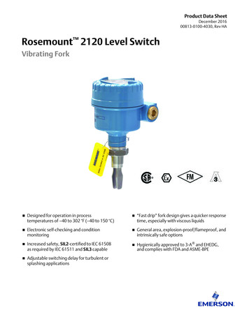
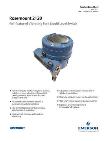
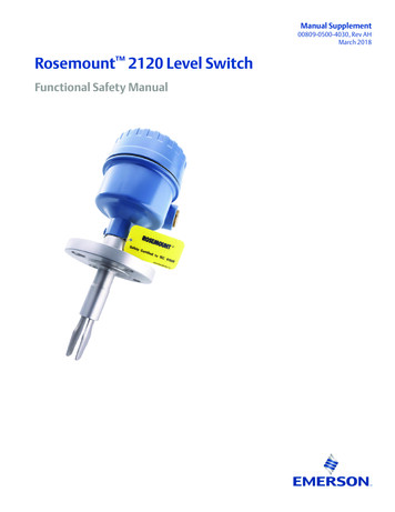
Rosemount 2120 Level Switch Vibrating Fork. . Use the level switch only as specified in this manual. Failure to do so may impair the protection provided by the level switch. The weight of a level switch with a heavy flange and extended fork length may exceed 37 lb. (18 kg). A risk assessment is required before carrying,