Transcription
Reference Manual00809-0100-4030, Rev DAJune 2007Rosemount 2120Vibrating Fork Liquid Level Switchwww.rosemount.com
Reference Manual00809-0100-4030, Rev DAJune 2007Rosemount 21202120 Vibrating Fork Liquid Level SwitchIMPORTANT NOTICERead this manual before working with the product. For personal and system safety, andfor optimum product performance, make sure you thoroughly understand the contentsbefore installing, using, or maintaining this product.The United States has two toll-free assistance numbers and one International number.Customer Central1-800-999-9307 (7:00 a.m. to 7:00 P.M. CST)International1-(952) 906-8888National Response Center1-800-654-7768 (24 hours a day)Equipment service needsCAUTIONThe products described in this document are NOT designed for nuclear-qualifiedapplications. Using non-nuclear qualified products in applications that require nuclearqualified hardware or products may cause inaccurate readings.For information on Emerson Process Management nuclear-qualified products, contactyour local Emerson Process Management Sales Representative.CAUTIONRosemount pursues a policy of continuous development and product improvement. Thespecification in this document may therefore be changed without notice. To the best of ourknowledge, the information contained in this document is accurate and Rosemountcannot be held responsible for any errors, omissions or other misinformation containedherein. No part of this document may be photocopied or reproduced without the priorwritten consent of Rosemount.www.rosemount.com
Reference ManualRosemount 212000809-0100-4030, Rev DAJune 2007
Reference Manual00809-0100-4030, Rev DAJune 2007Rosemount 2120Table of ContentsSECTION 1IntroductionSwitch Overview . . . . . . . . . . . . . . . . . . . . . . . . . . . . . . . . . . . . . . . . . . . . . . . . . . . . . . . .1-2Short Fork Technology . . . . . . . . . . . . . . . . . . . . . . . . . . . . . . . . . . . . . . . . . . . . . . . .1-2Rosemount 2120 Application and Mounting Examples. . . . . . . . . . . . . . . . . . . . . . . . . . .1-2Overfill Protection . . . . . . . . . . . . . . . . . . . . . . . . . . . . . . . . . . . . . . . . . . . . . . . . . . . .1-3Limit Detection . . . . . . . . . . . . . . . . . . . . . . . . . . . . . . . . . . . . . . . . . . . . . . . . . . . . . .1-3Pipe Installation (Pump Protection) . . . . . . . . . . . . . . . . . . . . . . . . . . . . . . . . . . . . . .1-3High and Low Level Alarm . . . . . . . . . . . . . . . . . . . . . . . . . . . . . . . . . . . . . . . . . . . . .1-3Hygienic Applications . . . . . . . . . . . . . . . . . . . . . . . . . . . . . . . . . . . . . . . . . . . . . . . . .1-3Application Considerations: . . . . . . . . . . . . . . . . . . . . . . . . . . . . . . . . . . . . . . . . . . . .1-4Handling the 2120 . . . . . . . . . . . . . . . . . . . . . . . . . . . . . . . . . . . . . . . . . . . . . . . . . . . . . . .1-4Device Identification . . . . . . . . . . . . . . . . . . . . . . . . . . . . . . . . . . . . . . . . . . . . . . . . . . . . .1-5Installation Considerations and Recommendations . . . . . . . . . . . . . . . . . . . . . . . . . . . . .1-6Switchpoint . . . . . . . . . . . . . . . . . . . . . . . . . . . . . . . . . . . . . . . . . . . . . . . . . . . . . . . . .1-8Service Support. . . . . . . . . . . . . . . . . . . . . . . . . . . . . . . . . . . . . . . . . . . . . . . . . . . . . . . . .1-8Warranty . . . . . . . . . . . . . . . . . . . . . . . . . . . . . . . . . . . . . . . . . . . . . . . . . . . . . . . . . . .1-8SECTION 2InstallationSafety Messages. . . . . . . . . . . . . . . . . . . . . . . . . . . . . . . . . . . . . . . . . . . . . . . . . . . . . . . .2-1Mechanical Installation . . . . . . . . . . . . . . . . . . . . . . . . . . . . . . . . . . . . . . . . . . . . . . . . . . .2-2Correct Fork Alignment . . . . . . . . . . . . . . . . . . . . . . . . . . . . . . . . . . . . . . . . . . . . . . . . . . .2-2Pipe Installation . . . . . . . . . . . . . . . . . . . . . . . . . . . . . . . . . . . . . . . . . . . . . . . . . .2-3Vessel Installation . . . . . . . . . . . . . . . . . . . . . . . . . . . . . . . . . . . . . . . . . . . . . . . .2-3Cable Gland Orientation . . . . . . . . . . . . . . . . . . . . . . . . . . . . . . . . . . . . . . . . . . . . . . . . . .2-4Set Mode Switch / Switching Time Delay . . . . . . . . . . . . . . . . . . . . . . . . . . . . . . . . . . . . .2-4LED Indication . . . . . . . . . . . . . . . . . . . . . . . . . . . . . . . . . . . . . . . . . . . . . . . . . . . . . . . . . .2-6Electrical Installation . . . . . . . . . . . . . . . . . . . . . . . . . . . . . . . . . . . . . . . . . . . . . . . . . . . . .2-72120 Direct Load Switching . . . . . . . . . . . . . . . . . . . . . . . . . . . . . . . . . . . . . . . . . . . .2-72120 PNP/PLC Version . . . . . . . . . . . . . . . . . . . . . . . . . . . . . . . . . . . . . . . . . . . . . . .2-92120 Relay Output . . . . . . . . . . . . . . . . . . . . . . . . . . . . . . . . . . . . . . . . . . . . . . . . . .2-112120 Intrinsically Safe NAMUR . . . . . . . . . . . . . . . . . . . . . . . . . . . . . . . . . . . . . . . .2-13www.rosemount.com
Reference ManualRosemount 212000809-0100-4030, Rev DAJune 2007SECTION 3Service & TroubleshootingMagnetic Test Point. . . . . . . . . . . . . . . . . . . . . . . . . . . . . . . . . . . . . . . . . . . . . . . . . . . . . .3-1Inspection . . . . . . . . . . . . . . . . . . . . . . . . . . . . . . . . . . . . . . . . . . . . . . . . . . . . . . . . . . . . .3-22120 Maintenance. . . . . . . . . . . . . . . . . . . . . . . . . . . . . . . . . . . . . . . . . . . . . . . . . . . . . . .3-2Troubleshooting. . . . . . . . . . . . . . . . . . . . . . . . . . . . . . . . . . . . . . . . . . . . . . . . . . . . . . . . .3-3Spare Parts . . . . . . . . . . . . . . . . . . . . . . . . . . . . . . . . . . . . . . . . . . . . . . . . . . . . . . . . . . . .3-3Replacement and Calibration of Electronic (PCB) Cassettes . . . . . . . . . . . . . . . . . . . . . .3-4Replacement Sequence . . . . . . . . . . . . . . . . . . . . . . . . . . . . . . . . . . . . . . . . . . . . . . .3-4To replace the cassette, do the following: . . . . . . . . . . . . . . . . . . . . . . . . . . . . . .3-5Calibration Sequence . . . . . . . . . . . . . . . . . . . . . . . . . . . . . . . . . . . . . . . . . . . . . . . . .3-6APPENDIX AReference DataSpecifications . . . . . . . . . . . . . . . . . . . . . . . . . . . . . . . . . . . . . . . . . . . . . . . . . . . . . . . . . A-1Physical . . . . . . . . . . . . . . . . . . . . . . . . . . . . . . . . . . . . . . . . . . . . . . . . . . . . . . . . . . A-1Mechanical . . . . . . . . . . . . . . . . . . . . . . . . . . . . . . . . . . . . . . . . . . . . . . . . . . . . . A-1Performance . . . . . . . . . . . . . . . . . . . . . . . . . . . . . . . . . . . . . . . . . . . . . . . . . . . . . . . A-2Functional . . . . . . . . . . . . . . . . . . . . . . . . . . . . . . . . . . . . . . . . . . . . . . . . . . . . . . . . . A-2Electrical. . . . . . . . . . . . . . . . . . . . . . . . . . . . . . . . . . . . . . . . . . . . . . . . . . . . . . . A-4Dimensional Drawings. . . . . . . . . . . . . . . . . . . . . . . . . . . . . . . . . . . . . . . . . . . . . . . . . . . A-5Threaded Mounting. . . . . . . . . . . . . . . . . . . . . . . . . . . . . . . . . . . . . . . . . . . . . . . . . . A-5Flange Mounting . . . . . . . . . . . . . . . . . . . . . . . . . . . . . . . . . . . . . . . . . . . . . . . . . . . . A-6Hygienic Fitting . . . . . . . . . . . . . . . . . . . . . . . . . . . . . . . . . . . . . . . . . . . . . . . . . . . . . A-7Ordering Information . . . . . . . . . . . . . . . . . . . . . . . . . . . . . . . . . . . . . . . . . . . . . . . . . . . . A-8Spare Parts and Accessories . . . . . . . . . . . . . . . . . . . . . . . . . . . . . . . . . . . . . . . . A-11APPENDIX BProduct CertificationsOrdinary Location Certification for FM. . . . . . . . . . . . . . . . . . . . . . . . . . . . . . . . . . . . . . .Ordinary Location Certification for CSA . . . . . . . . . . . . . . . . . . . . . . . . . . . . . . . . . . . . .European Directive Information. . . . . . . . . . . . . . . . . . . . . . . . . . . . . . . . . . . . . . . . . . . .ATEX Directive (94/9/EC). . . . . . . . . . . . . . . . . . . . . . . . . . . . . . . . . . . . . . . . . .Pressure Equipment Directive (PED) (97/23/EC). . . . . . . . . . . . . . . . . . . . . . . .L.V. Directive . . . . . . . . . . . . . . . . . . . . . . . . . . . . . . . . . . . . . . . . . . . . . . . . . . .Electro Magnetic Compatibility (EMC) Directive. . . . . . . . . . . . . . . . . . . . . . . . .Vibration Resistance . . . . . . . . . . . . . . . . . . . . . . . . . . . . . . . . . . . . . . . . . . . . .CE-mark . . . . . . . . . . . . . . . . . . . . . . . . . . . . . . . . . . . . . . . . . . . . . . . . . . . . . . .Overfill protection . . . . . . . . . . . . . . . . . . . . . . . . . . . . . . . . . . . . . . . . . . . . . . . . . . . . . .Approved Manufacturing Locations. . . . . . . . . . . . . . . . . . . . . . . . . . . . . . . . . . . . . . . . .Hazardous Locations Certifications. . . . . . . . . . . . . . . . . . . . . . . . . . . . . . . . . . . . . . . . .North American and Canadian Approvals . . . . . . . . . . . . . . . . . . . . . . . . . . . . . . . . . . . .Factory Mutual (FM) Explosion Proof Approval . . . . . . . . . . . . . . . . . . . . . . . . . . . .Canadian Standards Association (CSA) Explosion Proof Approval . . . . . . . . . . . . .Instructions specific to hazardous area installations . . . . . . . . . . . . . . . . . . . . .Factory Mutual (FM) Intrinsically Safe Approval . . . . . . . . . . . . . . . . . . . . . . . . . . . .Canadian Standards Association (CSA) Intrinsically Safe Approval . . . . . . . . . . . 2B-2B-5B-5
Reference Manual00809-0100-4030, Rev DAJune 2007Rosemount 2120Canadian Standards Association (CSA) Non-Incendive Approval . . . . . . . . . . . . . . B-5Instructions specific to hazardous (classified locations) area installations. . . . . B-5European Approvals . . . . . . . . . . . . . . . . . . . . . . . . . . . . . . . . . . . . . . . . . . . . . . . . . . . B-10ATEX Flame Proof Approvals. . . . . . . . . . . . . . . . . . . . . . . . . . . . . . . . . . . . . . . . . B-10Instructions specific to hazardous area installations . . . . . . . . . . . . . . . . . . . . B-10(Reference European ATEX Directive 94/9/EC, Annex II, 1.0.6.) . . . . . . . . . . B-10ATEX Intrinsically Safe Approval . . . . . . . . . . . . . . . . . . . . . . . . . . . . . . . . . . . . . . B-12Instructions specific to hazardous area installations . . . . . . . . . . . . . . . . . . . . B-12IECEx Approvals . . . . . . . . . . . . . . . . . . . . . . . . . . . . . . . . . . . . . . . . . . . . . . . . . . . . . . B-14IECEx Flame Proof Approvals . . . . . . . . . . . . . . . . . . . . . . . . . . . . . . . . . . . . . . . . B-14Instructions specific to hazardous area installations . . . . . . . . . . . . . . . . . . . . B-14IECEx Intrinsically Safe Approval . . . . . . . . . . . . . . . . . . . . . . . . . . . . . . . . . . . . . . B-16Instructions specific to hazardous area installations . . . . . . . . . . . . . . . . . . . . B-16National Supervision and Inspection Centre (NEPSI) Approvals . . . . . . . . . . . . . . . . . B-18NEPSI Explosion Proof Approval . . . . . . . . . . . . . . . . . . . . . . . . . . . . . . . . . . . . . . B-18TOC-3
Reference ManualRosemount 2120TOC-400809-0100-4030, Rev DAJune 2007
Reference Manual00809-0100-4030, Rev DAJune 2007SECTION 1Rosemount 2120INTRODUCTIONSwitch Overview . . . . . . . . . . . . . . . . . . . . . . . . . . . . . . . . . . . . . . . . . . . . . page 1-2Rosemount 2120 Application and Mounting Examples . . . . . . . . . . . . . page 1-2Handling the 2120 . . . . . . . . . . . . . . . . . . . . . . . . . . . . . . . . . . . . . . . . . . . . page 1-4Device Identification . . . . . . . . . . . . . . . . . . . . . . . . . . . . . . . . . . . . . . . . . page 1-5Installation Considerations and Recommendations . . . . . . . . . . . . . . . . page 1-6Service Support . . . . . . . . . . . . . . . . . . . . . . . . . . . . . . . . . . . . . . . . . . . . . page 1-8Procedures and instructions in this manual may require special precautions to ensure thesafety of the personnel performing the operations. Information that raises potential safetyissues is indicated by a caution symbol ( ). The external hot surface symbol ( ) is usedwhen a surface is hot and care must be taken to award possible burns. If there is a risk of anelectrical shock the ( ) symbol is used. Refer to the safety messages listed at thebeginning of each section before performing an operation preceded by this symbol.Failure to follow these installation guidelines could result in death or seriousinjury. Protection afforded by compliance to EN61010-1 (2001) may be impaired if theequipment is not used as specified. The Rosemount 2120 is a liquid level switch. It must be installed, connected,commissioned, operated and maintained by suitably qualified personnel only,observing any national and local requirements that may apply. Ensure the wiring is suitable for the electrical current and the insulation is suitable forthe voltage, temperature and environment.External Surface may be hot. Care must be taken to avoid possible burns.Process leaks could result in death or serious injury. Do not remove the level switch while in operation. Removing while in operation maycause process fluid leaks.Electrical shock could cause death or serious injury. If the level switch is installed in a high voltage environment and a fault condition orinstallation error occurs, high voltage may be present on switch leads and terminals. Use extreme caution when making contact with the leads and terminals.www.rosemount.com
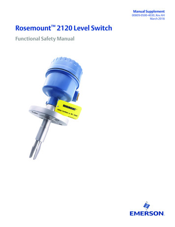
Reference Manual00809-0100-4030, Rev DAJune 2007Rosemount 2120Any substitution of non-recognized parts may jeopardize safety and is under nocircumstances allowed.Switch OverviewThe Rosemount 2120 is a liquid point level switch based on the vibrating short forktechnology making it suitable for virtually all liquid applications. Complete range of processconnections, wide choice of housing and wetted parts materials, four different switchingfunctions, extended fork lengths, hazardous area and overfill approvals makes itconfigurable to almost all requirements.Visible heartbeatLEDMode switch,adjustable timedelayIP66/67 or NEMA4Xhousings in plastic,aluminum or 316 SSTDirect Load, Relay PLC/PNP,or IS NAMUR electronicsMagnetic testpointTwo cable/ conduitentriesShort fork length orextensions up to 118-in. (3 m)‘Fast drip’fork designWetted material in SST, Hastelloy orHalar/PFA coating21210/2120 top off.tifThreaded, Flanged, orHygienic ConnectionsShort Fork TechnologyThe natural frequency ( 1300Hz) of the fork is chosen to avoid interference from plantvibration which may cause false switching. This also gives short fork length for minimalintrusion into vessel and pipe. Using Short Fork Technology, the Rosemount 2120 isdesigned for use in virtually all liquid applications. Extensive research has maximized theoperational effectiveness of the fork design making it suitable for almost all liquids, includingcoating liquids (avoid bridging of forks), aerated liquids, and slurries.Rosemount 2120 Application and Mounting ExamplesFor most liquids including coating and aerated liquids and slurries, the function is virtuallyunaffected by flow, turbulence, bubbles, foam, vibration, solid particles, build-up (avoidbridging of forks) or properties of the liquid. For use in Hazardous (IS or Exd) or safe areaand process temperatures up to 302 F (150 C).Mount in any position in the tank or pipe. Mounting is by a wide range of threaded,flanged, or hygienic connection.1-2
Reference Manual00809-0100-4030, Rev DAJune 2007Rosemount 2120Overfill ProtectionSpillage caused by overfilling can be hazardous to people and theenvironment, resulting in lost product, and clean up costs. The 2120 is alimit level switch with a built-in visible ‘heartbeat LED’ used to signal overfillat any time.Limit DetectionOften batch processing tanks contain stirrers/agitators to ensure mixingand product ‘fluidity’. The standard user selectable time delay ranging from0.3 to 30 seconds virtually eliminates the risk of false switching due tosplashing caused by stirrers/agitators.Pipe Installation (Pump Protection)Short forks mean minimum intrusion wetside and allow simple low costinstallation at any angle into your pipes or vessels. With the fork projectingonly 2-in. (50 mm) (dependent on connection type), the 2120 can beinstalled in even small diameter pipes. By selecting the option of direct loadswitching electronics, the 2120 is ideal for reliable pump control and can beused to protect against pumps running dry.High and Low Level AlarmMaximum and minimum level detection in tanks containing many differenttypes of liquids are an ideal application for the 2120. The robust 2120operates continuously at temperatures up to 302 F (150 C) and operatingpressure up to 1450 psig (100 barg) making it perfect for use as a high orlow level alarm.Hygienic ApplicationsWith the option of highly polished forks providing a surface finish (Ra)better than 0.8μm, the 2120 meets the principle design criteria of the moststringent hygienic requirements used in food and beverage, andpharmaceutical applications. Manufactured in stainless steel the 2120 isrobust enough to easily withstand steam cleaning (CIP) routines attemperatures up to 302 F (150 C).1-3
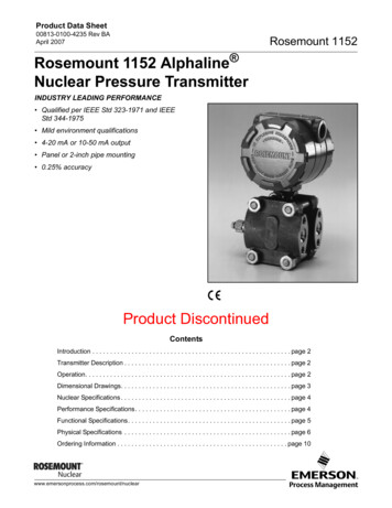
Reference Manual00809-0100-4030, Rev DAJune 2007Rosemount 2120Application Considerations: Ensure liquid is inside the temperature and pressure ranges (see specifications). Check that the liquid is inside recommended viscosity range 0.2 to 10,000 cP. Examples of products with too high of viscosity are chocolate syrup, ketchup, peanutbutter and bitumen. The switch will still detect these products but the drain time can bevery long. Check that the liquid density is above 37.5 lb/ft3 (600 kg/m3). Examples of products with too low of density are acetone, pentane and hexane. Check for risk of build-up on the forks. Avoid situations where drying and coating products may create excessive build-up. Ensure no risk of bridging the forks. If coating, bridging may occur ensure the Halar/PFA coated version is used to reducethe risk of build-up. Examples of products that can create bridging of forks are dense paper slurries andbitumen. Check the solids content in the liquid. Problems may occur if product coats and dries causing caking. As a guideline maximum solid particle diameter in the liquid is 0.2-in. (5 mm). Extra consideration is needed when dealing with particles bigger than 0.2-in. (5 mm),consult factory. Foam In almost all cases the 2120 is insensitive to foams (do not see the foam as a liquid). However in rare occasions some very dense foams may be seen as liquid, knownexample of this is found in ice-cream and orange juice manufacturing.Handling the 21201-4Figure 1-2. Do not alter the 2120 forks in any way.2120/fig2.jpg2120/fig1.jpgFigure 1-1. Do not hold the 2120 by forks.
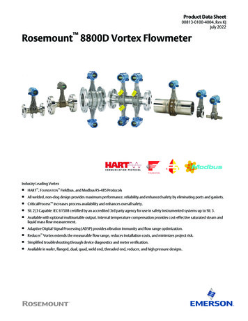
Reference Manual00809-0100-4030, Rev DAJune 2007Rosemount 2120Device IdentificationSee Appendix B: Product Certifications for specific product approvals.2120 Vibrating Fork Level IR E C T L OAD S WIT C HINGSupply 20 - 264V ac 50 - 60Hz20 - 60VdcOutput Rating:Load 20 - 500mA2120/2120 24aa.epswww.rosemount.comwww .rosemount.com1-5
Reference ManualRosemount 212000809-0100-4030, Rev DAJune 2007Installation Considerations and RecommendationsBefore you install the Rosemount 2120 Level Switch, consider specific installationrecommendations and mounting requirements. Install in any orientation in tank containing liquid. Always install in the normally “on” state. (See “Electrical Installation” on page 2-7) For high level the recommendation is Dry on. For low level the recommendation is Wet on. Always ensure the system is tested by using the local magnetic test point duringcommissioning. (See “Magnetic Test Point” on page 3-1) Ensure sufficient room for mounting and electrical connection (See “DimensionalDrawings” on page A-5 for switch dimensions.)2120/2120 28aa.epsFigure 1-3. Ensure Adequate Space Outside Tank Ensure that the forks do not come into contact with the tank wall or any internal fittingsor obstructions. Avoid installing the 2120 where it will be exposed to liquid entering the tank at the fillpoint. Avoid heavy splashing on the forks. Raising the time delay reduces accidental switching caused by splashing. Avoid product buildup. Ensure no risk of bridging the forks. Ensure there is sufficient distance between build-up on the tank wall and the fork. Ensure installation do not create tank crevices around the forks where liquid maycollect (important high viscosity and high density liquids).1-6
Reference Manual00809-0100-4030, Rev DAJune 2007Rosemount 21202120/fig9.epsFigure 1-4. Example of ok and not ok build-up on tank wall. Extra consideration is needed if the plant vibration is close to the 1300 Hz operatingfrequency of the 2120 Avoid Long Fork Length and Vibration without Supporting the ForkFigure 1-5. Support fork if high dynamic loads. 3.28 ft(1.0 m)3.28 ft(1.0 m)2120/2120 29aa.eps3.28 ft(1.0 m)1-7
Reference Manual00809-0100-4030, Rev DAJune 2007Rosemount 2120SwitchpointIn the top diagram a lowerdensity media will giveswitchpoint closer to theconnection. A higher densitymedia will give switchpointcloser to fork tip. 0.039-in. ( 1 mm)0.5-in. (13 mm)Switchpoint (H20) (SP)0.5-in. (13 mm)Switching hysteresis (HY) 0.039-in. ( 1 mm)2120/fig12.eps0.5-in. (13 mm)Service SupportTo expedite the return process outside of the United States, contact the nearest Rosemountrepresentative.Within the United States, call the Rosemount National Response Center using the1-800-654-RSMT (7768) toll-free number. This center, available 24 hours a day, will assistyou with any needed information or materials.The center will ask for product model and serial numbers, and will provide a Return MaterialAuthorization (RMA) number. The center will also ask for the process material to which theproduct was last exposed.Rosemount National Response Center representatives will explain the additionalinformation and procedures necessary to return goods exposed to hazardous substancecan avoid injury if they are informed of and understand the hazard. If the product beingreturned was exposed to a hazardous substance as defined by OSHA, a copy of therequired Material Safety Data Sheet (MSDS) for each hazardous substance identified mustbe included with the returned goods.WarrantyEmerson Process Management will replace a faulty or failed 2120 with a new unit providedthat the fault or failure is reported either directly or via an accredited representative, within 1year from the date of supply, and the product has been installed and used in accordancewith Emerson Process Management instruction manual 00809-0100-4030. EmersonProcess Management reserves the right to examine such product and to refuse replacementat its discretion if the above conditions are not met.1-8
Reference Manual00809-0100-4030, Rev DAJune 2007SECTION 2Rosemount 2120INSTALLATIONSafety Messages . . . . . . . . . . . . . . . . . . . . . . . . . . . . . . . . . . . . . . . . . . . . page 2-1Mechanical Installation . . . . . . . . . . . . . . . . . . . . . . . . . . . . . . . . . . . . . . . page 2-2Correct Fork Alignment . . . . . . . . . . . . . . . . . . . . . . . . . . . . . . . . . . . . . . . page 2-2Cable Gland Orientation . . . . . . . . . . . . . . . . . . . . . . . . . . . . . . . . . . . . . . page 2-4Set Mode Switch / Switching Time Delay . . . . . . . . . . . . . . . . . . . . . . . . . page 2-4LED Indication . . . . . . . . . . . . . . . . . . . . . . . . . . . . . . . . . . . . . . . . . . . . . . page 2-6Electrical Installation . . . . . . . . . . . . . . . . . . . . . . . . . . . . . . . . . . . . . . . . . page 2-7Safety MessagesProcedures and instructions in this manual may require special precautions to ensure thesafety of the personnel performing the operations. Information that raises potential safetyissues is indicated by a caution symbol ( ). The external hot surface symbol ( )is usedwhen a surface is hot and care must be taken to award possible burns. If there is a risk of anelectrical shock the ( )symbol is used. Refer to the safety messages listed at thebeginning of each section before performing an operation preceded by this symbol.www.rosemount.com
Reference ManualRosemount 212000809-0100-4030, Rev DAJune 2007Mechanical InstallationFigure 2-1. SealingNPT,BSPT (R)threadFigure 2-2. Tighten the SwitchPTFE(Teflon)GasketTri-Clamp2120/fig3, fig4.epsBSPP (G)threadSeal (supplied in02100-1020-0001)Correct Fork AlignmentAlignment groove2-22120/fig6.epsEnsure correct fork alignment.
Reference Manual00809-0100-4030, Rev DAJune 2007Rosemount 21202120/fig7.epsPipe Installation2120/fig8.epsVessel Installation2-3
Reference ManualRosemount 212000809-0100-4030, Rev DAJune 20072120/fig10.epsCable Gland OrientationSet Mode Switch / Switching Time DelayPLC/PNPOPERATION MODE OUT-Dry On ModeDryWetDryWet12-4234Wet On ModeDry On0.31Wet On0.313310103030Seconds Delay2120/fig11.epsModeSwitch/TimeDelayLED
Reference ManualRosemount 212000809-0100-4030, Rev DAJune 20071. Mode switchDry on or wet on mode selection.2. Switching time delay0.3, 1, 3, 10, or 30 seconds time delay selection.Figure 2-3. Mode Dry On, 1 second time delay (typical for high level applications)Wet On0.310.313310103030Seconds DelayMode Dry ON2120/fig11a, fig13b.epsDry OnFigure 2-4. Mode Wet On, 1 second time delay (typical for low level applications)Mode Wet On0.31Wet On0.313310103030Seconds Delay2120/fig11b, fig13c.epsDry OnNOTE: There is a five second delay when switching between modes and time delays. The small cut-out in the rotating switch indicates the delay/mode chosen. Recommended installation for high level is dry on and low level is wet on. Do not installin the normally ‘off’ state.2-5
Reference ManualRosemount 212000809-0100-4030, Rev DAJune 2007LED Indication2-6LED Flash RateSwitch StatusContinuousOutput state is on1 every secondOutput state is off1 every 2 secondsUncalibrated1 every 4 secondsLoad fault; load current too high; load short circuit2 times / secondIndication of successful calibration3 times / secondInternal fault (micro, ROM, or RAM)OffProblem (e.g. supply)
Reference ManualRosemount 212000809-0100-4030, Rev DAJune 2007Electrical InstallationIsolate supply before connecting the switch or removing the electronics.The functional earth terminal must be connected to an external earthing system.2120 Direct Load Switching Direct load switching (2-wire, Red label)OPERATION MODEDry On ModeDryWetLOAD LINEDryWet12PE(Ground)Wet On Mode3RDry OnWet On0.310.313310103030Seconds DelayFuse 2A(T)Direct LoadSwitchingWARNINGIsolate SupplyBefore RemovingR External load (must be fitted)R Charge externe (impératif)DPSTR Extern last (måste monteras som visas)ILNeutral0VR Externe Last (muß installiert sein)Live VU 20 - 264V (ac) (50/60Hz)IOFF 3mAIL 20 - 500mAî 5A, 40msU 20 - 60V (dc)IOFF 3mAIL 20 - 500mAî 5A, 40msR Carga exterior (debeinstalarse)R Externe belasting (moetaangesloten zijn)R Zewnetrzne obciazenie (musi byc podlaczone) Load Off Load OnNOTE:DPST ‘Double Pole, Single Throw’ (on/off) switch - must be fitted for safe disconnection ofthe power supply. Fit the switch as near to the 2120 as possible. Keep the switch free ofobstructions. Label the switch to indicate that it is the supply disconnection device for the2120.RELAY CONNECTION WARNING:The Rosemount 2120 requires a minimum current of 3mA, which continues to flow when the2120 is ‘off’. If selecting a relay to wire in series with the 2120, the user must ensure that thedrop-out voltage of the relay is greater than the voltage which will be generated across therelay coil when 3mA flows through it.2-7
Reference ManualRosemount 212000809-0100-4030, Rev DAJune 2007High level Dry ONDry On0.31Low level Wet ONDry OnWet On0.310.313333103010103030Seconds DelaySeconds Delay'U 3mAIL12VFuse2A(T)L VLED on continuously2-8'UFuse2A(T)DPSTDPSTN0V0.311030ILWet OnN0VIL12VFuse2A(T)DPSTL VLED flashes every secondN0V 3mAILFuse2A(T)DPSTL VLED on continuouslyN0VL VLED flashes every second
Reference ManualRosemount 212000809-0100-4030, Rev DAJune 20072120 PNP/PLC Version PNP output for load switching and direct PLC switching (3-wire, Yellow label)PLC/PNPOPERATION MODE Dry On ModeDryWet-OUTDryWet2Wet On Mode34O/P0V0.31Wet On0.313310103030Seconds DelayFuse 2A(T)1Dry OnEarth(Ground) VU 20 - 60VI 4mA IL(dc)IL (MAX) 0 - 500mAî 5A, 40msUOUT(ON) U - 2.5VIL (OFF) 100μA2-9
Reference ManualRosemount 212000809-0100-4030, Rev DAJune 2007High level Dry ONDry On0.31Low level Wet ONDry OnWet On0.310.313333103010103030Seconds DelayPLC (positive input)-OUTSeconds Delay -OUT PLCPNP dc ΔURIL -OUT Fuse1A(T)-OUT ΔUIL 100μA I/PPLCRFuse1A(T)IL -OUTR 3VLED on continuously LED flashes every second2-10 I/PPLCR 3VFuse1A(T) PLC-OUTILILI/P-OUT 100μA 3VILI/P ΔU 100μAIL-OUT ΔU 3V 0.311030 Wet OnILFuse1A(T) 100μA LED on continuously LED flashes every second
Reference ManualRosemount 212000809-0100-4030, Rev DAJune 20072120 Relay Output Relay output, SPCO (Green label)RELAYOPERATION MODENDry On ModeDryWetLDryWet12PE(Ground)Wet On0.310.313310103030Wet On Mode3Dry OnSeconds DelayFuse 0.5A (T)NCCNO456NCCNOUMAX 250V (ac)DPSTIMAX 5ANLivePMAX' 1250VA, cos φ 1U 20 - 264V (ac) (50/60Hz)PMAX' 1000VA, cos φ 0.7I 6mA Load Off0V VU 2
Rosemount 2120 June 2007 1-2 Switch Overview The Rosemount 2120 is a liquid point level switch based on the vibrating short fork technology making it suitable for virtually all liquid applications. Complete range of process connections, wide choice of housing and wetted parts materials, four different switching