Transcription
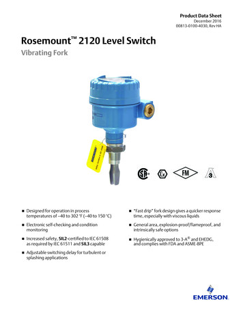
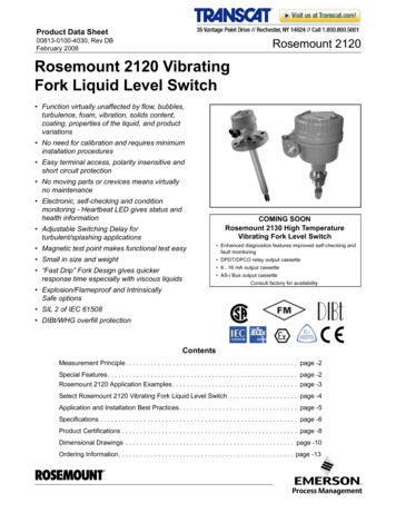
Product Data SheetRosemount 212000813-0100-4030, Rev DBFebruary 2008Rosemount 2120 VibratingFork Liquid Level Switch Function virtually unaffected by flow, bubbles,turbulence, foam, vibration, solids content,coating, properties of the liquid, and productvariations No need for calibration and requires minimuminstallation procedures Easy terminal access, polarity insensitive andshort circuit protection No moving parts or crevices means virtuallyno maintenance Electronic, self-checking and conditionmonitoring - Heartbeat LED gives status andhealth informationCOMING SOONRosemount 2130 High TemperatureVibrating Fork Level Switch Adjustable Switching Delay forturbulent/splashing applications Magnetic test point makes functional test easy Enhanced diagnostics features improved self-checking andfault monitoring Small in size and weight DPDT/DPCO relay output cassette “Fast Drip” Fork Design gives quickerresponse time especially with viscous liquids 8.16 mA output cassette AS-i Bus output cassetteConsult factory for availability. Explosion/Flameproof and IntrinsicallySafe options SIL 2 of IEC 61508 DIBt/WHG overfill protectionContentsMeasurement Principle . . . . . . . . . . . . . . . . . . . . . . . . . . . . . . . . . . . . . . . . . . . . . . . . page -2Special Features . . . . . . . . . . . . . . . . . . . . . . . . . . . . . . . . . . . . . . . . . . . . . . . . . . . . . page -2Rosemount 2120 Application Examples . . . . . . . . . . . . . . . . . . . . . . . . . . . . . . . . . . . page -3Select Rosemount 2120 Vibrating Fork Liquid Level Switch . . . . . . . . . . . . . . . . . . . page -4Application and Installation Best Practices . . . . . . . . . . . . . . . . . . . . . . . . . . . . . . . . . page -5Specifications . . . . . . . . . . . . . . . . . . . . . . . . . . . . . . . . . . . . . . . . . . . . . . . . . . . . . . . page -6Product Certifications . . . . . . . . . . . . . . . . . . . . . . . . . . . . . . . . . . . . . . . . . . . . . . . . . page -8Dimensional Drawings . . . . . . . . . . . . . . . . . . . . . . . . . . . . . . . . . . . . . . . . . . . . . . . page -10Ordering Information. . . . . . . . . . . . . . . . . . . . . . . . . . . . . . . . . . . . . . . . . . . . . . . . . page -13www.rosemount.com
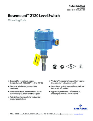
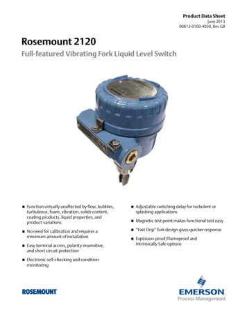
Product Data SheetRosemount 212000813-0100-4030, Rev DBFebruary 2008Superior Reliability in a Universal PackageThe Rosemount 2120 is a liquid point level switchbased on the vibrating short fork technology makingit suitable for virtually all liquid applications. Completerange of process connections, wide choice ofhousing and wetted parts materials, four differentswitching functions, extended fork lengths,hazardous area and overfill approvals make itconfigurable to almost all requirements.MEASUREMENT PRINCIPLEThe Rosemount 2120 is a liquid point level switchdesigned using the principle of a tuning fork. Apiezo-electric crystal is used to oscillate the forks attheir natural frequency. Changes to this frequencyare continuously monitored. When the 2120 is usedas a low alarm, the liquid in the vessel drains downpast the fork, resulting in a change of naturalfrequency; this is detected by the electronics whichswitch the output state. When used as a high alarm,the liquid rises in the vessel, makes contact with thefork and again the output switches.Short Fork TechnologyThe natural frequency ( 1300Hz) of the fork hasbeen chosen to avoid interference from plantvibration which may cause false switching. Thisallows for minimum intrusion into the vessel or pipethrough the use of a short fork. Using Short ForkTechnology, the Rosemount 2120 is designed for usein virtually all liquid applications. Extensive researchhas maximized the operational effectiveness of thefork design making it suitable for almost all liquids,including coating liquids (avoid bridging of forks),aerated liquids, and slurries.Heartbeat LEDThe Rosemount 2120 has a status indicatingheartbeat LED which can be seen at all times andfrom all angles through a lens in the cover (no lens inmetal housings). The LED will flash when the 2120 is‘off’ and will be constantly lit when it is ‘on’. The LEDgives constant indication that the 2120 is functioningcorrectly (different flash rates are used to indicateproduct malfunction) and gives local indication of theprocess state.Magnetic Test PointA magnetic test point is located on the side of thehousing, allowing the user to perform a functionaltest of the 2120 and the system connected to it. Byholding a magnet to the target, the 2120 output willchange state for as long as the magnet is held.Electrical HookupThe terminal blocks extend above the housing andgive easy terminal access. The polarity insensitivityand short circuit protection make electrical hook-upsafe and easy.Fork DesignThe “fast drip” fork design (liquid is drawn away fromthe fork tips) together with a short switching delayallow the 2120 to react more quickly and havegreater sensitivity to density variations.Visibleheartbeat LEDEasyterminalaccessSPECIAL FEATURESMode Switch/Adjustable Time DelayA mode switch allows the 2120 to be set to switchfrom wet to dry (typically low alarm) or from dry towet (typically high alarm). There is also a userselectable time delay from 0.3, 1, 3, 10, or 30seconds. Increasing the time delay in turbulent orsplashing applications virtually eliminates the risk offalse switching.2Mode switch,adjustable timedelayPolarityinsensitive andshort circuitprotectionMagnetictest point“Fast drip”fork designShort forklength
Product Data SheetRosemount 212000813-0100-4030, Rev DBFebruary 2008ROSEMOUNT 2120 APPLICATIONEXAMPLESOverfill witch High integrity Manual testfacilitySpillage caused by overfilling can be hazardous to people and the environment,resulting in lost product and potentially high clean up costs. The 2120 is a limitlevel switch used to signal overfill at any time. The 2120 is available withDIBt/WHG overfill protection approval. Heartbeat LEDwww.rosemo2120unt.comVibratingForkLevelSwitch Time delayswitching optionBatch processing tanks often contain stirrers/agitators to ensure mixing andproduct ‘fluidity’. The standard user selectable time delay ranging from 0.3 to 30seconds virtually eliminates the risk of false switching due to splashing causedby stirrers/agitators. Resistance tofalse switching2120 Choice ofelectronicoutputsLimit Pipe Installation (Pump Protection) Small forks Low cost Reliable IP66/67,Type 4Xwww.rosem2120ount.comVibratingForkLevelSwitch Range ofprocessconnectionsHigh and Low Level AlarmMaximum and minimum level detection in tanks containing many different typesof liquids are ideal applications for the 2120. The robust 2120 operatescontinuously at temperatures up to 302 F (150 C) and operating pressures upto 1450 psig (100 barg) making it perfect for use as a high or low level alarm. Itis common practice to fit an independent high level alarm switch as a backupdevice to any other level device installed in case of primary device ing Hightemperature High ing Plastic, SST, oraluminumhousingShort forks mean minimum intrusion wetside and allow simple low costinstallation at any angle into your pipes or vessels. With the fork projecting only2-in. (50 mm) (dependant on connection type), the 2120 can be installed ineven small diameter pipes. By selecting the option of direct load switchingelectronics, the 2120 is ideal for reliable pump control and can be used toprotect against pumps running dry.www.rosemoHygienic Applications2120unt.comVibratingFork Hygienicsurface finish Extended fork Install anywhereWith the option of highly polished forks providing a surface finish (Ra) betterthan 0.8µm, the 2120 meets the principle design criteria of the most stringenthygienic requirements used in food and beverage, and pharmaceuticalapplications. Manufactured in stainless steel the 2120 is robust enough toeasily withstand steam cleaning (CIP) routines at temperatures up to 302 F(150 C).3LevelSwitch
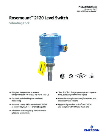
Product Data SheetRosemount 212000813-0100-4030, Rev DBFebruary 2008SELECT ROSEMOUNT 2120 VIBRATINGFORK LIQUID LEVEL SWITCHThe Rosemount 2120 switch consists of housing,tank connection, and forks. The tank connection andforks are the only wetted parts.Tank Connection and ForkFork LengthShort fork for minimum intrusion installation(minimum 2-in. [50 mm]) or fork extensions up to118-in. (3m) are available. See “DimensionalDrawings” on page 10.Threaded ConnectionThreads: R 3/4-in. and 1-in. (BSPT); G 3/4-in. and1-in. (BSPP); 3/4-in. and 1-in. NPTDirect Load,Relay,PLC/PNP, or ISNAMURelectronicsTwo cable/conduitentriesMaterial: 316L SST, Hastelloy CIP66/67 or Type 4Xhousings inplastic, aluminumor 316 SSTThreaded, Flanged, orHygienic ConnectionsShort fork length orextensions up to118-in. (3 m)Wetted material in SST,Hastelloy or Halar/PFA coatingSwitch HousingThe switch housing is available in glass filled nylon,aluminum or SST with two M20, 1/2-in., or 3/4-in. NPTcable/conduit entries. It can be ordered withIntrinsically Safe or Explosion Proof / Flame Proofapprovals. Approval depends on the housing type,see Product Certifications on page 14.ElectronicsStandard two core cable can be used with any powersupply from 20 to 264V ac (50/60 Hz) or 20 to 60V dcto connect the 2120 in series with a load to achievedirect load switching. The output acts as a simpleSPST switch that changes state with liquid presence.Alternatively the switching function of the SPCOrelay electronics output can be used. The 2120 alsohas the option of electronics that can be interfaceddirectly to a PLC using the PNP transistor outputmodel (three-wire). The Intrinsically Safe (IS) 2120 toATEX EEx ia approval interfaces directly withstandard NAMUR (DIN 19234, IEC60947-5-6,EN50227) isolation amplifiers.4Accessories: A stainless steel adjustable clampgland is available for use with extended length2120 (1-in. models only). This is threaded 11/2-in.BSPP for connection to the vessel, and allows the1-in. extended length 2120 to be raised orlowered as desired then clamped in position. SeeSpare Parts and Accessories on page 16.Flanged ConnectionsFlange: ANSI B16.5 (1.5-in. or larger), BS4504(DN40 or larger)Material: 316L SST, Halar/PFA coated,other on requestHygienic ConnectionsFittings: 1.5-in. (38 mm) or 2-in. (51 mm)Tri-Clamp, 1-in. BSPP (G) O-ring seal, or other onrequestMaterial: 316L SSTOptions: Hand polished wetside to a finish betterthan 0.8µm meets the principle design criteria ofthe most stringent hygienic requirements.Accessories: A mounting kit comprising vesselfitting, Nitrile seal and clamp ring is available foruse with 2-in. (51 mm) Tri-Clamp 2120. A fittingboss with Fluorocarbon (FPM/FKM) O-ring isavailable for use with O-ring seal 2120. SeeSpare Parts and Accessories on page 16.1.5-in. (38 mm)or 2-in. (51 mm)Tri-Clamp
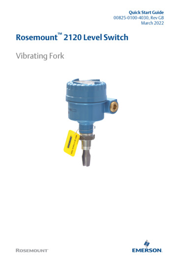
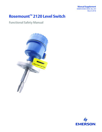
Product Data SheetRosemount 212000813-0100-4030, Rev DBFebruary 2008APPLICATION AND INSTALLATION BEST PRACTICESApplication Considerations: Ensure liquid is inside the temperature andpressure ranges (see specifications). Check that the liquid is inside recommendedviscosity range 0.2 to 10,000 cP. Examples of products that are too viscousare chocolate syrup, ketchup, peanut butterand bitumen. The switch will still detect products above10,000 cP, however, the drain times becomeprohibitively long or cleaning may becomenecessary to resume dry functioning. Check that the liquid density is above 37.5lb/ft3 (600 kg/m3). Examples of products with densities too loware propane and propylene. Check for risk of build-up on the forks. Avoid situations where drying and coatingproducts may create excessive build-up. Ensure there is no risk of bridging the forks. If coating or bridging may occur, ensure theHalar/PFA coated version is used to reducethe risk of build-up. Examples of products that can createbridging of forks are dense paper slurriesand bitumen. Recommended Installation: Always install in the normally “on” state. For high level is Dry on. For low level is Wet on. Always ensure the system is tested by usingthe local magnetic test point duringcommissioning. Ensure sufficient room for mounting andelectrical connection (See page -10 for switchdimensions). Avoid installing the 2120 where it will beexposed to liquid entering the tank at the fillpoint. Avoid heavy splashing on the forks. Raising the time delay reduces accidentalswitching caused by splashing. Ensure that the forks do not come into contactwith the tank wall or any internal fittings orobstructions. Ensure there is sufficient distance betweenbuild-up on the tank wall and the fork.FIGURE 1. Example of OK and not OK build-upon tank wall.Check the solids content in the liquid. Problems may occur if product coats anddries causing caking. As a guideline maximum solid particlediameter in the liquid is 0.2-in. (5 mm). Foam In almost all cases the 2120 is insensitive tofoams (does not see the foam).2120/fig9.eps Extra consideration is needed when dealingwith particles bigger than 0.2-in. (5 mm),consult factory. However in rare occasions some very densefoams may be seen as liquid, knownexample of this is found in ice-cream andorange juice manufacturing.5
Product Data SheetRosemount 212000813-0100-4030, Rev DBFebruary esis (water)Rosemount 2120 Vibrating Fork Liquid Level Switch 0.039-in. ( 1mm) nom.Measuring principleSwitching Point (water)Vibrating Fork0.5-in. (13 mm) from tip (vertical) / from edge (horizontal) of fork(this will vary with different liquid densities).ApplicationsMost liquids including coating liquids, aerated liquids, and slurriesMechanicalMaximum Operating PressureFinal rating depends on tank connectionHousing/EnclosureHousing CodeHousingmaterialADNylon PA6630%GFLED WindowConduit P66/67 toEN60529XYAl alloy ASTMB26 356-T6 orLM25 TFnoneM203/4-in.NPTIP66/67 toEN60529,Type 4XST316C12StainlessSteelnoneM203/4-in.NPTIP66/67 toEN60529,Type 4XThreaded ConnectionSee Figure 2.Note: Clamp gland (02120-2000-0001), see page -16, limitsthe maximum operating pressure to 18.85 psig (1.3 barg).Hygienic Connection435 psig (30 barg)Flanged ConnectionSee Figure 2 and Table 1 (whichever one is lower).FIGURE 2. Process PressureProcess Pressure psig (barg)See Process Connection Size / Type on page 13.Extended LengthsAvailable as standard to a maximum of 118-in. (3000 mm),other on requestProcess Material316L Stainless Steel (1.4404), Hastelloy C or Halar (ECTFE) / PFAco-polymer coating (39.37-in. [1000 mm] max). Hand polished tobetter than 0.8µm option available for hygienic connections.Gasket material for 3/4 in. and 1 in. BSPP (G) is Non-asbestosBS7531 Grade X carbon fiber with rubber binder.2120/2120 18AB.EPSConnections1450 (100)1160 (80)32 (0)-14.5 (-1.0)-40 32(-40) (0)122(50)302(150)Process Temperature F ( C)Dimensional DrawingsSee “Dimensional Drawings” on page 10TABLE 1. Maximum Flange Pressure RatingStandardClass/RatingSST FlangesANSIANSIANSIDINDINDINDIN150 lb.300 lb.600 lb.PN 10/16PN 25/40PN 64PN 100275 psig(1)720 psig(1)1,440 psig(1)10/16 barg(2)25/40 barg(2)64 barg(2)100 barg(2)(1) At 100 F (38 C), the rating decreases with increasing temp.(2) At 248 F (120 C), the rating decreases with increasing temp.6
Product Data SheetRosemount 212000813-0100-4030, Rev DBFebruary 2008TemperatureGroundingSee Figure 3.The 2120 should always be grounded either through the terminalsor using the external ground connection provided.FIGURE 3. Temperature Direct load switching (two-wire)176 (80)2120/2120 18AC.EPSAmbient Temperature F ( C)Electrical Connections122 (50)32 (0)-40 (-40)-40 32(-40) (0)140(60)OPERATION MODEDry On12RPE(Ground)103030ILLive0V VIsolate SupplyBefore RemovingSeconds DelayU 20 - 60V (dc)IOFF 3mAIL 20 - 500mAî 5A, 40ms Solid state PNP output for direct interface to PLC’s (three wire)Minimum 37.5 lb/ft3 (600 kg/m3)PLC/PNPOPERATION MODEDry On ModeDryWet-OUT Dry OnWetDry0.2 to 10,000 cP (centiPose)2Maximum recommended diameter of solid particles in the liquid is0.2-in. (5 mm). V0V33101030Seconds DelayU 20 - 60VI 4mA ILO/P0.3130Wet On Mode43Fuse 2A(T)1Earth(Ground)Wet On0.31Liquid Viscosity RangeSolids Content and CoatingWARNINGU 20 - 264V (ac) (50/60Hz)IOFF 3mAIL 20 - 500mAî 5A, 40msDPSTProcess Temperature F ( C)310R External load (must be fitted)Fuse 2A(T)Neutral0.313Wet On Mode3Direct LoadSwitchingWet On0.31WetDry302(150)Liquid Density RangeDry On ModeDryWetLOAD LINE(dc)IL (MAX) 0 - 500mAî 5A, 40msU OUT(ON) U - 2.5VFor coating product, avoid bridging of forks.IL (OFF) 100μASwitching DelayUser selectable 0.3, 1, 3, 10, 30 seconds delay dry towet/wet to dry SPCO single relay for voltage free contactsCIP (Clean In Place) CleaningDry On ModeDryWetLWithstands steam cleaning routines up to 302 F (150 C)WetDry1ElectricalDry OnWet On0.310.313310103030Wet On Mode32PE(Ground)NLive VProtection56NCCNOP MAX' 1250VA, resistive(dc)U MAX 60VI 6mA(dc)IMAX 5A, U 30VTerminal Connection (wire diameter)(2.5mm2)IMAX 1.5A, U 60V Intrinsically Safe (IS) NAMUR to DIN 19234, IEC 60947-5-6(Note national regulations)OPERATION MODE-Dry On ModeDryWet Conduit Plugs/Cable GlandWetDry Metal Ex d Housing: Conduit entries for explosion proof areasare shipped with two brass conduit plugs.1 Plastic housing with relay electronics are shipped with twoPA66(1) cable glands.Wet On Mode2Dry On0.31Wet On3310103030Intrinsically SafeEN 50227/ NAMUR0.31Seconds DelayION 2.2 . 2.5 mA Plastic housing with direct load, PNP/PLC and IS electronicsare shipped with one PA66(1) cable gland and one blankingplug.(1)4P MAX' 1000VA, inductiveU 20 - 60VPolarity insensitive. Over-current, short-circuit and load-missingprotection. Surge protection to IEC61326.Max.NOIMAX 5AU 20 - 264V (ac) (50/60Hz)I 6mA0VCU MAX 250V (ac)DPSTUser selectable (Dry on or Wet on)NCSeconds DelayFuse 0.5A (T)Switching Mode0.1-in2RELAYOPERATION MODENIOFF 0.8 . 1.0 mA Isolating amplifier to NAMUR (IEC60947-5-6, EN50227) —must be used to meet I.S. requirementsCable diameter 0.2 to 0.3-in. (5 to 8 mm)7
Product Data SheetRosemount 212000813-0100-4030, Rev DBFebruary 2008Product CertificationsORDINARY LOCATION CERTIFICATIONFOR FMG5Project ID: 3024095The switch has been examined and tested to determine thatthe design meets basic electrical, mechanical, and fireprotection requirements by FM, a nationally recognizedtesting laboratory (NRTL) as accredited by the FederalOccupational Safety and Health Administration (OSHA).HAZARDOUS LOCATIONSCERTIFICATIONSNorth American ApprovalsFactory Mutual (FM) Explosion Proof ApprovalE5ORDINARY LOCATION CERTIFICATIONFOR CSAG6Certificate Number: 06 CSA 1796535The switch has been examined and tested to determine thatthe design meets basic electrical, mechanical, and fireprotection requirements by CSA, a nationally recognizedtesting laboratory as accredited by the Standards Council ofCanada (SCC).Enclosure: Type 4XFactory Mutual (FM) Intrinsically Safe ApprovalI5EUROPEAN DIRECTIVE INFORMATIONThe EC declaration of conformity for all applicable Europeandirectives for this product can be found on the Rosemount websiteat www.rosemount.com. A hard copy may be obtained bycontacting your local sales office.Project ID: 3024095Explosion Proof for Class I, Div. 1, Groups A, B, C and DTemperature Class:T6 (Tamb -40 C to 75 C)Project ID: 3024095Intrinsically Safe for Class I, Div. 1, Groups A, B, C and DClass I, Zone 0, AEx ia IICTemperature Code:T5 (Tamb -40 C to 80 C, Tproc 80 C)Control Drawing: 71097/1154Ui 15 V, Ii 32 mA, Pi 0.1 W, Ci 211 nF, Li 0.06 mHNOTEA NAMUR isolating amplifier must be used for intrinsic safety.ATEX Directive (94/9/EC)Complies with the ATEX Directive.Pressure Equipment Directive (PED) (97/23/EC)Canadian Approvals2120 is outside the scope of PED Directive.Canadian Standards Association (CSA)Explosion Proof ApprovalsL.V. DirectiveE6EN61010-1 Pollution degree 2, Category II (264V max), Pollutiondegree 2, Category III (150V max)Electro Magnetic Compatibility (EMC) DirectiveEnclosure: Type 4XEN61326 Emissions to Class B.Immunity to industrial location requirements.Vibration ResistanceEN60721 level 3M6/4M6Project ID: 1796535Explosion Proof for Class I, Div. 1, Groups A, B, C, and DTemperature Class:T6 (Tamb -40 C to 75 C)Canadian Standards Association (CSA)Intrinsically Safe ApprovalI6CE-markComplies with applicable directives (EMC, ATEX, LVD)Overfill ProtectionCertificate Number: 06 CSA 1796535Intrinsically Safe for Class I, Div. 1, Groups A, B, C, and DClass 1, Zone 0, Ex ia IICTemperature Code:T5 (Tamb -40 C to 80 C, Tproc 80 C)Control Drawing: 71097/1179Ui 15 V, Ii 32 mA, Pi 0.1 W, Ci 211 nF, Li 0.06 mHOption available for DIBt/WHGSIL Declaration of ConformityRosemount 2120 IS Namur Vibrating Fork Level Sensor Models2120***C*I** has demonstrated proven reliability. It ismanufactured and supported in a manner suitable for applicationsup to SIL 2 of IEC 61508 as a Type B Safety Related Subsystemwhen configured as a high level alarm(1) in conjunction with aNamur Barrier(1).8(1)Refer to manual for IEC 61508 configuration details.
Product Data SheetRosemount 212000813-0100-4030, Rev DBFebruary 2008Canadian Standards Association (CSA)Non-Incendive ApprovalI6Certificate Number: 06 CSA 1796535Non-Incendive for Class I, Div. 2, Groups A, B, C, and DTemperature Code:T5 (Tamb -40 C to 80 C, Tproc 80 C)International ApprovalsNational Supervision and Inspection Centre forExplosion Protection and Safety Instrumentation(NEPSI) Intrinsically Safe ApprovalI3Control Drawing: 71097/1187Ui 15 V, Ii 32 mA, Pi 0.1 W, Ci 211 nF, Li 0.06 mHNOTEA NAMUR isolating amplifier must be used for intrinsic safety.European ApprovalsATEX Flameproof ApprovalE1Certificate: Sira 05ATEX1129Flame Proof:ATEX MarkingII 1/2 G DEEx d IIC T6 (Tamb -40 C to 75 C)Ui 15 V, Ii 32 mA, Pi 0.1 W, Ci 12 nF, Li 0.06 mHNOTEA NAMUR isolating amplifier must be used for intrinsic safety.International Electrotechnical Commission (IEC)Flame Proof ApprovalE7ATEX Intrinsically Safe ApprovalI1Certificate: Sira 05ATEX2130XIntrinsic Safety:ATEX MarkingII 1 G DEEx ia IIC T5 (Tamb -40 C to 80 C)Ui 15 V, Ii 32 mA, Pi 0.1 W, Ci 12 nF, Li 0.06 mHNOTEA NAMUR isolating amplifier must be used for intrinsic safety.Certificates:GYJ06530 (when manufactured in Slough, UK)GYJ06531 (when manufactured in Singapore, Singapore)Intrinsic Safety:Ex ia IIC T5 (Tamb -40 C to 60 C)Certificate: IECEx SIR 06.0051Flame Proof and Dust:Zone 0/1Ex d IIC T6 (Tamb -40 C to 75 C)Ex tD A21 T85 C (Tamb -40 C to 75 C) IP6XInternational Electrotechnical Commission (IEC)Intrinsically Safe ApprovalI7Certificate: IECEx SIR 06.0070XIntrinsically Safe and Dust:Ex ia IIC T5, Ex iaD 20 T85 (Tamb -40 C to 80 C)Ui 15 V, Ii 32 mA, Pi 0.1 W, Ci 12 nF, Li 0.06 mHNOTEA NAMUR isolating amplifier must be used for intrinsic safety.9
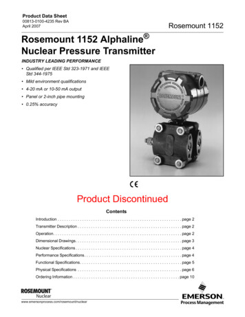
Product Data SheetRosemount 212000813-0100-4030, Rev DBFebruary 2008Dimensional DrawingsThreaded MountingGlass Filled NylonGlass Filled NylonBBAluminum/SSTBCCC5.60(142)2120 02AA, 2120 03AA, 2120 17BACable entryM20x1.5 or3/4-in. NPTD1.575 (40) A/Fhexagon3/4-or1-in.E (M)or1-in.2.72(69)DCable entryM20x1.5 or1/2-in. NPT3/4-CableGland1.575 (40) A/Fhexagon1.73(44)3/4- or 1-in.2.72(69)0.51 (13)Switchpoint0.91 0.040.51 (13)(23 1)Switchpoint1.14 0.04(29 1)0.51 (13)Switchpoint0.91 0.04(23 1)1.14 0.04(29 1)0.51 (13)Switchpoint1.73(44)0.51 (13)Switchpoint0.51 (13)Switchpoint0.91 0.04(23 1)1.14 0.04(29 1)NoteDimensions are in inches (millimeters)TABLE 2. Fork Length. Dimensions are in inches (millimeters)Standard LengthModel Code AMinimum LengthModel Code E (M)Maximum LengthModel Code E (M)/4-in.1.73 (44)3.74(95)118.11 (3000)1-in.1.73 (44)3.70 (94)118.11 (3000)Thread3TABLE 3. Housing Dimensions. Dimensions are in inches (millimeters)10MaterialBCDGlass Nylon3.52 (90)4.02 (102)4.72 (120)Aluminum2.68 (68)4.02 (102)6.14 (156)316 Stainless Steel2.76 (70)4.13 (105)6.30 (160)
Product Data SheetRosemount 212000813-0100-4030, Rev DBFebruary 2008Flange Mounting(Glass filled nylon housing shown)BCDCableGland0.51 (13)Switchpoint2120 09AAE (M)1.14 0.04(29 1)0.51 (13)SwitchpointNoteDimensions are in inches (millimeters)TABLE 4. Dimensions are in inches (millimeters)MaterialStandard LengthModel Code HMinimum LengthModel Code E (M)Maximum LengthModel Code E (M)Stainless Steel4 (102)3.50 (89)118.11 (3000)Halar/PFA co-polymer coated4 (102)3.50 (89)39.37 (1000)TABLE 5. Housing Dimensions. Dimensions are in inches (millimeters)MaterialBCD(1)Glass Nylon3.52 (90)4.02 (102)6.30 (160)Aluminum2.68 (68)4.02 (102)6.14 (156)Stainless Steel2.76 (70)4.13 (105)7.87 (200)(1) Will vary with flange rating and thickness. “D” is nominal maximum thickness and allows a flange up to 1.77-in. (45 mm) thick. This equates to a 4-in. ANSI,600lb. RF.11
Product Data SheetRosemount 212000813-0100-4030, Rev DBFebruary 2008Hygienic Fitting(Glass filled nylon housing shown)BBBCCCDD1-in. BSPPO-ring sealCableGland1.5-in. or 2-in.Tri-Clamp2.52(64)E (M)1.73(44)0.51 (13)Switchpoint0.51 (13)SwitchpointCableGlandCableGland3.07(78)1.5-in. or 2-in.Tri-Clamp0.51 (13)Switchpoint0.91 0.04(23 1)1.575 (40)A/F Hexagon0.91 0.04(23 1)0.51 (13)Switchpoint0.51 (13)Switchpoint0.51 (13)SwitchpointNoteDimensions are in inches (millimeters)1.14 0.04(29 1)TABLE 6. Dimensions are in inches (millimeters)ConnectionStandard LengthModel Code AMinimum LengthModel Code E (M)Maximum LengthModel Code E (M)Tri-Clamp1.7 (44)4.13 (105)118.11 (3000)O-ring Seal (1-in. BSPP)1.7 (44)NANATABLE 7.122120 05AA, 2120 10AA, 2120 20AADMaterialBCDGlass Nylon3.52 (90)4.02 (102)4.96 (126)Aluminum2.68 (68)4.02 (102)6.14 (156)Stainless Steel2.76 (70)4.13 (105)6.54 (166)
Product Data SheetRosemount 212000813-0100-4030, Rev DBFebruary 2008Ordering InformationModel2120CodeDN(1)(2)Product DescriptionVibrating Fork Liquid Level SwitchMaterial of Construction: Process Connection/Fork316L Stainless Steel (1.4404)316L SST (1.4404) with NACE compliance to MR 0175:2003 (ISO 15156:2003), MR 0103-2003F(3)Halar/PFA, coated 316L SST (1.4404)C(4)Hastelloy C, solid HastelloyCodeProcess Connection Size / TypeThreaded0A30B30D31A1-in. BSPT (R) thread1B1-in. BSPP (G) thread1D1-in. NPT thread/4-in. BSPT (R) thread/4-in. BSPP (G) thread/4-in. NPT threadHygienic fitting1P1-in. BSPP (G), O-ring5R1.5-in. (38 mm) Tri-Clamp2R2-in. (51 mm) Tri-ClampANSI Flanges5G1.5-in. ANSI, 150 lb. RF5H1.5-in. ANSI, 300 lb. RF5J1.5-in. ANSI, 600 lb. RF2G2-in. ANSI, 150 lb. RF2H2-in. ANSI, 300 lb. RF2J2-in. ANSI, 600 lb. RF3G3-in. ANSI, 150 lb. RF3H3-in. ANSI, 300 lb. RF3J3-in. ANSI, 600 lb. RF4G4-in. ANSI, 150 lb. RF4H4-in. ANSI, 300 lb. RF4J4-in. ANSI, 600 lb. RFDIN (EN) Flanges5KDN40, PN 10/165LDN40, PN 25/405MDN40, PN 645NDN40, PN 1002KDN50, PN 10/162LDN50, PN 25/402MDN50, PN 642NDN50, PN 1007KDN65, PN 10/167LDN65, PN 25/407MDN65, PN 647NDN65, PN 1003KDN80, PN 10/163LDN80, PN 25/403MDN80, PN 643NDN80, PN 1004KDN100, PN 10/1613
Product Data SheetRosemount 21204LDN100, PN 25/404MDN100, PN 644N00813-0100-4030, Rev DBFebruary 2008DN100, PN 100Other Process ConnectionXX(5)Customer SpecificCodeElectronic TypeAvailable for CertificationsSDirect load switching (2 wire) 20 to 264Vac 50/60Hz, 20 to 60 VdcNA, E1, E5, E6, E7, G5, G6BPNP/PLC low voltage switching (3 wire) 20 to 60VdcNA, E1, E5, E6, E7, G5, G6RRelay (SPDT/SPCO)NA, E1, E5, E6, E7, G5, G6C(6)CodeIS NAMUR (Ex ia)1Standard surface finish2Hand polished (Ra 0.8 µm)CodeI1, I3, I5, I6, I7Surface Finish (Wetted Parts)AllHygienic Connection OnlyAvailable for ElectronicAvailable for HousingNo Hazardous Locations CertificationsS, B, RA, DG5(7)FM Ordinary Locations (unclassified, safe area)S, B, RY, TG6(8)CSA Ordinary Locations (unclassified, safe area)S, B, RY, TNAProduct CertificationsAvailable for ConnectionsATEX FlameproofS, B, RX, SE5(7)FM Explosion ProofS, B, RY, TE6(8)CSA Explosion ProofS, B, RY, TIECEx Explosion ProofS, B, RX, SA, DE1E7I1ATEX Intrinsic SafetyCI3NEPSI Intrinsic SafetyCA, DI5FM Intrinsic SafetyCA, DI6CSA Intrinsically Safe and Non-IncendiveCA, DI7IECEx Intrinsic SafetyCA, DCodeHousingAvailable for CertificationsAGlass Filled Nylon, M20 conduits/cable threadsNA, I1, I3, I5, I6, I7DGlass Filled Nylon, 1/2-in. NPT conduits/cable threadsNA, I1, I3, I5, I6, I7XAluminum Alloy, M20 conduits/cable threadsYAluminum Alloy, 3/4-in. NPT conduits/cable threadsSStainless Steel, M20 conduits/cable threadsTStainless Steel 3/4-in. NPT conduits/cable threadsCodeAFork LengthStandard length 1.7-in. (44 mm)E1, E7E5, E6, G5, G6E1, E7E5, E6, G5, G6Available ConnectionAll except flanged modelsH(2)Standard length flange 4.0-in. (102 mm)B(2)Ext 5.9-in. (150 mm)All except Tri-clamp 5R and 2RAll flanged modelsC(2)Ext 11.8-in. (300 mm)All except Tri-clamp 5R and 2RD(2)Ext 19.7-in. (500 mm)All except Tri-clamp 5R and 2RL(9)Semi-ext 3.9-in. (98 mm)1A, 1B, and 1DSpecific Extended Fork LengthE(10)Extended, Customer Specified Length in tenth of InchesM(10)Extended, Customer Specified Length in Millimetersxxxx(10)CodeAll except 1-in. BSPP o-ring seal 1PSpecific customer specified length in inches or millimeters (only if fork length E or M is selected)OptionsCalibration Data CertificationQ4Certificate of functional testMaterial Traceability CertificationQ8(1)(2)Material Traceability Certification per EN 10204 3.1BSpecial ProceduresP1(11)14All except 1-in. BSPP o-ring seal 1PHydrostatic Testing
Product Data Sheet00813-0100-4030, Rev DBFebruary 2008Rosemount 2120OverfillU1(12)DIBt/WHG Overfill protectionTag PlatesSTTag plate SST engraved plate (maximum 16 digits)WTTag plate laminated paper (maximum 40 digits)Typical Model: 2120 D 0A C 1 I1 A A Q8 ST(1) Only available for wetted parts.(2) Not available for hand
Rosemount 2120 February 2008 4 SELECT ROSEMOUNT 2120 VIBRATING FORK LIQUID LEVEL SWITCH The Rosemount 2120 switch consists of housing, tank connection, and forks. The tank connection and forks are the only wetted parts. Switch Housing The switch housing is available in glass filled nylon, aluminum or SST with two M20, 1/2-in., or 3/4-in. NPT