Transcription
NDE 2017 Conference & Exhibition of the Indian Society for NDT (ISNT), 14-16 December 2017, Chennai, T.N., IndiaComparative study between ERS Sensors and VWSGHina Gupta1*, Debdutta Ghosh1, Siddharth Behera1, A K Mittal1More info about this article: http://www.ndt.net/?id 223401Structural Engineering Group, CSIR-Central Building Research Institute, Roorkee*cbrihina@gmail.comAbstractNon-destructive evaluation is widely used for condition assessment and monitoring of structures. NDT methodsinvolve determining certain physical and chemical properties of the material which can be related to strengthand durability of structures. The parameter measured in the present study is elastic/inelastic deformations i.e.strain in the structure under variable loading conditions. Various types of sensors are being used now days forstrain measurement in structures including electrical resistance strain gauge (ERS), fiber optic sensor (FOS) andvibrating wire strain gauge (VWSG) etc. Strain measurements based on ERS may not be suitable for long-termmonitoring due to electromagnetic interference and other complications associated with the endurance ofsensors but can be appropriately used for short term non-destructive evaluation (NDE) of structures. It can beused as a very cheap substitute of high cost VWSG and FOS. This paper describes the feasibility of ERS forNDE of structures. Comparative analysis on Vibrating wire strain gauge (VWSG) sensor and electrical straingauge for strain measurements has been carried out. Experimentation has been conducted at CSIR-CBRI, on asteel specimen and loaded under compression as well tension. A correlation has been generated between theresults obtained from both types of strain gauges and ERS are found suitable for NDE of various structures i.e.concrete, masonry etc.Keywords: Vibrating Wire Strain Gauge, Electrical Resistance Strain Sensors, Structural Health Monitoring,Non-Destructive Evaluation1. IntroductionThe fields of non-destructive testing (NDT) and structural health monitoring (SHM)have become of great importance to inspect and maintain structures. Non DestructiveEvaluation (NDE) of structures refers to assessment of the condition of materials in thestructure using equipment external to the structure. It generally involves on-going or repeatedassessment of response of structures due to various types of loads. Various NDT techniquesthat are used these days may include Accelerometers; Acoustic Emission (AE); Digital ImageCorrelation (DIC); Electrical Resistance Strain Gauges (ERS); Fiber Optics; GlobalPositioning System (GPS); Ground Penetrating Radar (GPR); Infrared Thermography; LinearPotentiometer; Linear Variable Differential Transformer (LVDT); Potential Measurements(Chloride Content); Tiltmeters/Inclinometers; Ultrasonic C Scan; Vibrating Wire StrainGauge (VWSG) etc. Sensors are the crucial elements in the measurement process. Over thepast few decades, new advanced sensors and sensing methodologies have been developed inlaboratories and evaluated in the field. Although a lot of work has been done for using newtechniques like Vibrating Wire Strain Gauge and Fiber optics, still the Electrical ResistanceStrain Gauges are most widely and commonly used sensors for strain measurements.A lot of investigations has been done on structures using various sensors to assess theperformance of structures under different types loading. Strain gauges are basically strainsensitive material whose internal properties like Electrical resistance, vibrational frequencyetc. are proportional to the instantaneous spatial average strain over its surface. [1] Differentcategories of commercially available strain sensors are discrete strain sensors (to measurelocalized strain at the point where the sensor is installed), quasi-distributed strain sensors(discrete sensors connected in series) and highly distributed strain sensors (to measure thecomplete strain profile along the entire length of the sensor). [2]1
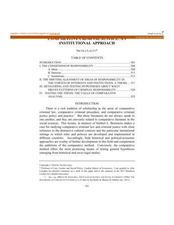
NDE 2017 Conference & Exhibition of the Indian Society for NDT (ISNT), 14-16 December 2017, Chennai, T.N., IndiaDifferent types of sensors are being employed for the monitoring of structuralresponses e.g. strain under various loadings in concrete, masonry and other materials. Thesesensors include electrical resistance strain gauge (ERS), fiber optic sensor (FOS) andvibrating wire strain gauge (VWSG) etc. Every sensor has its advantages and limitations likeVWSGs [3] and FOSs [4],[5],[6] are immune to electromagnetic interference whilemeasurement system from these two sensors is relatively expensive compared with ERSs. [7]Among these, FOS is the most expensive, fragile, and complicated to install. ERS and VWSGworks on simple measurement principles hence are appropriate for structural monitoring.[8]Vibrating Wire Strain Gauge is being used for measuring Small Strains in ConcreteBeams.[9], to monitor corrosion-induced deterioration of Concrete [10], measurement of lowamplitude hysteresis behavior of concrete [11] Also, durability and accuracy of embeddedvibrating wire strain gauges have been investigated for long-term measurement of strain inconcrete.[12] Analytical model has been developed for estimation of maximum normal stressin steel beam-columns using VWSG [13]. Numerous laboratory experiments have been doneto verify the precision and reliability of VWSGs over ERS sensors for measuring strain[4],[14],[15],[16], [17]. However, even though being the cheapest and simple, suitability ofERS sensors for Non Destructive Testing of structures is losing ground due to the its nonstatic behavior in measuring strains. This behavior of ERS has been investigated in thepresent study and suitability of these sensors has been established for strain measurements.2. Theory2.1 Vibrating wireVibrating wire strain gauge works on the principle that change in frequency f of atensioned wire corresponds to the change in the stress (Fig 1).LFigure 1 Schematic diagram of VWSG [16]The relation between fundamental natural frequency f of a tensioned wire and itsstress is given by 12where ρ is the density and l is the length of the wire. For any elastic material, inabsence of thermal effects, stressand strain Ɛ are related as E Ɛ, where E is theYoung’s Modulus of the material. For any change in frequency of a vibrating wire, change instrain is given byƐ k (f22-f12)2
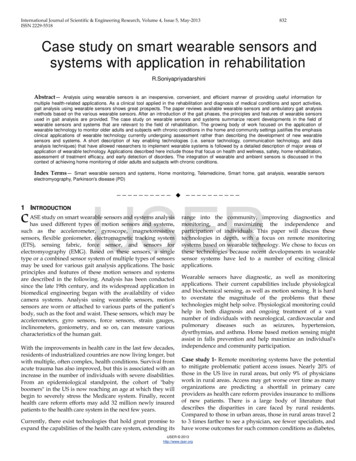
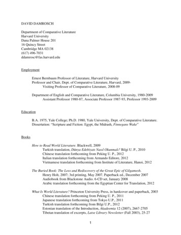
NDE 2017 Conference & Exhibition of the Indian Society for NDT (ISNT), 14-16 December 2017, Chennai, T.N., Indiawhere f1 and f2 are frequency of wire before and after change in loading. G is thegauge factor, which is a function of E, ρ and the gauge length. Operating principle for VWSGhas been well explained in the literatures [3], [11],[18],[19], [20], [21].2.2 ERS SensorsElectrical strain gauges (Fig 2) works on the principal that when its material isstretched, its length increases and its cross-section decreases; resulting an increase in itselectrical resistance. This change in resistance is a measure of its mechanical motion. Thus, astrain gauge uses change in electrical resistance to measure strain using principle ofWheatstone bridge.[1],[22],[23]Figure 2 Schematic diagram of ERS sensorThe relationship between change in resistance and strain in the wire used in straingauge is given as L 1 R RLwhere K is defined as the gauge factor of the wire, R is the change in resistance dueto strain, R is the initial resistance, L is the change in length, L is the original length of thewire, and L/L is the unit strain to which the wire is subjected.3. Experimental ResultsThe experimentation has been performed by setting up a steel box section under the 300 TUniversal Testing Machine (UTM) at the structural engineering laboratory of CentralBuilding Research Institute, Roorkee. The box section is made from welding two channelsection toe to toe. The cross sectional area of each channel section was 2088 mm2. Thesection is loaded and unloaded under the 300 T UTM in both tension and compression withsteps of 5 kN. Maximum 20 kN load in tension is applied to the composite box section.Thereafter unloaded and compression loading is applied. The respective strains are recordedfor each load increment using both ERS and VWSG. The experimental setup and dataacquisition system is shown in Figure 3a and b respectively. The fixing of VWSG and ERSsensor is shown in Figure 4 a and b respectively.3
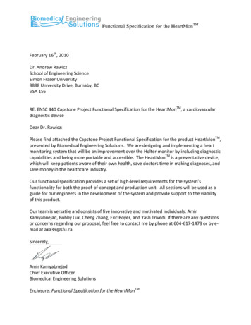
NDE 2017 Conference & Exhibition of the Indian Society for NDT (ISNT), 14-16 December 2017, Chennai, T.N., India(b)(a)Figure 3 a) Experimental setup b) Data acquisition system(a)(b)Figure 4 Fixing of a) Vibrating Wire Strain Gauge b) Electrical Resistance StrainGaugeBoth the sensors are installed in two opposite face of the box section. The data obtained fromVWSG are less fluctuating compared to ERS strain data. The variation of strains in ERS atdifferent instance of time during tension of the member is shown in Figure 5. It can be seenthat up-to /- 50 variation is present in the data. However, time averaging provides almostsimilar results obtained from the VWSG. Load application steps are shown in Figure 6a, b, c.4
NDE 2017 Conference & Exhibition of the Indian Society for NDT (ISNT), 14-16 December 2017, Chennai, T.N., IndiaFigure 5 Variation of micro strain with loading and unloading under Tension(b)(a)(c)Figure 6 (a) During loading under Tension, (b) unloading under Tension (c) Duringloading under CompressionAnalytical calculations have been done by using relation between the stress and strain i.e. E Ɛ, where E is the Young’s Modulus of the steel taken as 200 GPa. SinceA is area of cross section and P is the load applied. Thus, strain Ɛ wherecan be calculated foreach load.As we know the sectional property of the specimen, we can calculate the strain at anylocation of the member. Therefore, analytically strains are also calculated. The comparisonof micro-strain data for ERS, VWSG and analytical are shown in the Table 1 and 2respectively for tension and compression. Plot of this parameter is also shown in Figure 7.Table 1: Tension Load v/s micro strainTension Load 0Table 2: Compression Load v/s micro strainCompression Load(kN)0ERS (microstrain)3VWSG0Analytical05
NDE 2017 Conference & Exhibition of the Indian Society for NDT (ISNT), 14-16 December 2017, Chennai, T.N., 915417959.86197119.7239149.6549179.5859Figure 7 Plot of comparison ERS, VWSG and Analytical data4. ConclusionsThe paper focuses on appropriate NDE techniques for stress and strain measurements in steelstructures. VWSGs are widely used and established strain measuring technique for metallicstructures. These are known for its reading stability and accuracy. It can be seen from theabove results that, although ERS data is very fluctuating, stable results can be obtainedthrough appropriate time averaging scheme. ERS sensors are cheaper comparative to VWSGstrain measuring sensors. Another advantage is, this can be easily installed over any surfacesvery easily. New averaging of noise suppression technique may be developed for monitoringmuch steel members using ERS sensors.REFERENCES[1]E.J. Wilson, Chapter 17 Strain-Gage Instrumentation, in: Shock and Vibration Handbook, 1988: p. 17.1-17.15.[2]Y. Ge, M.Z.E.B. Elshafie, S. Dirar, C.R. Middleton, The response of embedded strain sensors in concrete beamssubjected to thermal loading, Construction and Building Materials. 70 (2014) ]Geokon, Vibrating Wire Strain Gage Model 4200ER- Instruction Manual, (2017).[4]M. Lydon, S.E. Taylor, D. Robinson, P. Callender, C. Doherty, S.K.T. Grattan, E.J. Obrien, Development of abridge weigh-in-motion sensor: Performance comparison using fiber optic and electric resistance strain sensorsystems, IEEE Sensors Journal. 14 (2014) 4284–4296. doi:10.1109/JSEN.2014.2332874.[5]C. Rodrigues, D. Inaudi, B. Glišić, Long-gauge fibre optic sensors: performance comparison and applications, Int. J.Lifecycle Performance Engineering Lifecycle Performance Engineering. (2005).[6]T. Dean, A. Hartog, T. Cuny, F. Englich, The Effects of Pulse Width on Fibre-optic Distributed Vibration SensingData, in: 78th EAGE Conference & Exhibition 2016 Vienna, Austria, 2016. doi:10.3997/2214-4609.201600684.[7]J.M.W. Brownjohn, Structural health monitoring of civil infrastructure, Philosophical Transactions of the RoyalSociety A: Mathematical, Physical and Engineering Sciences. 365 (2007) 589–622. doi:10.1098/rsta.2006.1925.6
NDE 2017 Conference & Exhibition of the Indian Society for NDT (ISNT), 14-16 December 2017, Chennai, T.N., India[8]H.M. Lee, H.S. Park, Measurement of maximum strain of steel beam structures based on average strains fromvibrating wire strain gages, Experimental Techniques, Society for Experimental Mechanics. 37 (2013) A. Neild, M.S. Williams, P.D. McFadden, Development of a vibrating wire strain gauge for measuring smallstrains in concrete beams, Strain. 41 (2005) 3–9. doi:10.1111/j.1475-1305.2004.00163.x.[10]X.C. Liu, J. Wei, Z.Y. Wang, Use of Vibrating Wire Strain Gauges to Monitor Corrosion-Induced Deterioration ofConcrete, Key Engineering Materials. 517 (2012) 357–362. . Neild, P.D. McFadden, M.S. Williams, A review of time-frequency methods for structural vibration analysis,Engineering Structures. 25 (2003) 713–728. doi:10.1016/S0141-0296(02)00194-3.[12]A. Simon, A. Courtois, T. Clauzon, E. Coustabeau, S. Vinit, Long-term measurement of strain in concrete :durability and accuracy of embedded vibrating wire strain gauges, in: SMAR 2015: Third Conference on SmartMonitoring, Assessment and Rehabilitation of Civil Structures, 2015.[13]H.M. Lee, S.W. Choi, D.J. Jung, H.S. Park, Analytical model for estimation of maximum normal stress in steelbeam-columns based on wireless measurement of average strains from vibrating wire strain gages, Computer-AidedCivil and Infrastructure Engineering. 28 (2013) 707–717. doi:10.1111/mice.12044.[14]H.S. Park, H.Y. Lee, S.W. Choi, Y. Kim, A practical monitoring system for the structural safety of mega-trussesusing wireless vibrating wire strain gauges, Sensors. 13 (2013) 17346–17361. doi:10.3390/s131217346.[15]Y. Ge, M.Z.E.B. Elshafie, S. Dirar, C.R. Middleton, The response of embedded strain sensors in concrete beamssubjected to thermal loading, Construction and Building Materials. 70 (2014) 6]H.M. Lee, J.M. Kim, K. Sho, H.S. Park, A wireless vibrating wire sensor node for continuous structural healthmonitoring, Smart Materials and Structures. 19 (2010) 55004. doi:10.1088/0964-1726/19/5/055004.[17]M. Lydon, S. Taylor, D. Robinson, C. Doherty, P. Callender, Assessment of Various Sensors for Structural HealthMonitoring for Bridge Weigh - in - Motion ( B - Wim ), The 6 Th International Conference on Structural HealthMonitoring of Intelligent Infrastructure. (2013).[18]A. Simonetti, A measurement technique for the vibrating wire sensors, IEEE. (2012) 1–6.doi:10.1109/NORCHP.2012.6403147.[19]R. Shepherd, Strain measurement using vibrating-wire gages, Experimental Mechanics I. 4 (1964) 244–248.[20]B. Mei, J. Lucas, S. Holé, I. Lamarque, N. Cheron, Origin of frequency difference between damped and sustainedmodes in vibrating wire sensors, Sensors and Actuators A: Physical. 241 (2016) 66–73.doi:10.1016/j.sna.2016.02.005.[21]J. Herranz, A. Barjau, B. Dehning, Vibration measurements of a wire scanner - Experimental setup and models,Mechanical Systems and Signal Processing. (2015) 974–994. doi:10.1016/j.ymssp.2015.08.025.[22]L. V Rohner, ELECTRICAL RESISTANCE STRAIN GAUGE: UNITED STATES PATENT OFFICE, 1947.[23]K. Hoffmann, Practical hints for the installation of strain gages, Hottinger Baldwin Messtechnik GmbH. (1996) 56.7
Vibrating wire strain gauge works on the principle that change in frequency f of a tensioned wire corresponds to the change in the stress (Fig 1). . Geokon, Vibrating Wire Strain Gage Model 4200ER- Instruction Manual, (2017). NDE 2017 Conference & Exhibition of the Indian Society for NDT (ISNT), 14-16 December 2017, Chennai, T.N., India .