Transcription
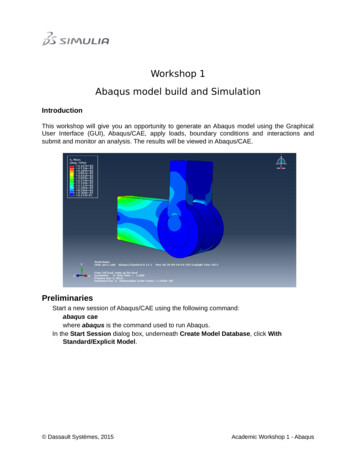
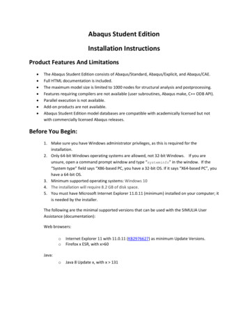
Quick guide to Abaqus/ CAEDr. Savvas TriantafyllouMethod of Finite Elements IIInstitute of Structural Engineering, ETHQUICK GUIDE TO ABAQUS/ CAEThe Abaqus/ CAE workspaceThe Abaqus/ CAE workspace (Fig. 1) consists of the following subsections that are going tobe mentioned throughout this guide, namely: The Viewport: The main output screen of Abaqus/ CAE where pre and post processingdata is visualized. The model Tree View: All the basic modelling steps are presented in this section in theform of tree nodes. Each node is subdivided into several subnodes offeringcorresponding functionalities. The Toolbar Section: Each node of the model Tree View has a corresponding toolbarfrom where the user can access relevant forms. The prompt region: Upon selecting to perform a certain function, tips and or commandbuttons appear on the prompt region.Fig. 1 Abaqus CAE workspace overviewPage 1 of 9
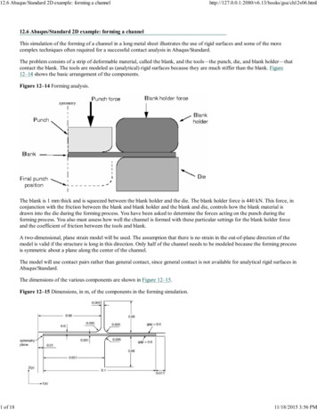
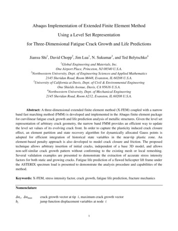
Quick guide to Abaqus/ CAEDr. Savvas TriantafyllouMethod of Finite Elements IIInstitute of Structural Engineering, ETHStep 1: File definitionStart Abaqus and choose to create a new model database. Remember to save in regulartime intervals throughout your session.Step 2: Geometry DefinitionIn the Model Tree double click on the Parts node (or right click on Parts and select Create) Fig. 2a.(b)(a)Fig. 2 (a) Model Tree view (b) Create Part formIn the Create Part form (Fig. 2b) check the appropriate parameters depending on yourstructure (in this case a 2D wire structure). Pressing Continue the sketch area appears that isbasically a CAD interface where you can draw the geometry of your model.Page 2 of 9
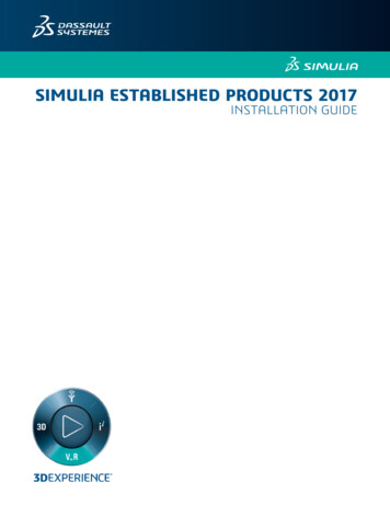
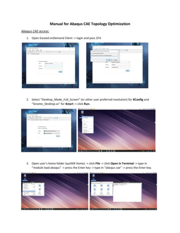
Quick guide to Abaqus/ CAEDr. Savvas TriantafyllouMethod of Finite Elements IIInstitute of Structural Engineering, ETHStep 3: Material DefinitionDouble click on the Materials node in the Model Tree (Fig. 3)Fig. 3 Material Node in Model Tree viewName the new material and give it a description. To define an Elastic Material click on theMechanical tab Elasticity Elastic and give appropriate values for the Young’s Modulusand the Poisson’s ratio (Fig. 4)Fig. 4 Edit Material Form – Elastic Material DefinitionTo add a nonlinear plastic law to the elastic material (e.g. consider the case of an elasticperfectly plastic Von-mises type material model), after defining the elastic properties on the“Mechanical” tab Plasticity Plastic and give appropriate values for the initial yield stressand initial plastic deformation. By pressing Enter, another row appears at the table whereyou should define more points in the stress plastic strain curve (i.e a failure stress and thecorresponding plastic strain) as presented in Fig. 5.Page 3 of 9
Quick guide to Abaqus/ CAEDr. Savvas TriantafyllouMethod of Finite Elements IIInstitute of Structural Engineering, ETHFig. 5 Edit Material Form – Von Mises Material DefinitionStep 4: Section DefinitionDouble click on the Sections node in the Model Tree (Fig. 6a). Name the section and selectBeam for the category to define a linear element Section and Truss for the type (Fig. 6b).Click Continue , select the material created from the dropbox and set the cross sectionalarea. Click OK.(a)(b)Fig. 6 (a) Sections node in Model Tree (b) Create Section formPage 4 of 9
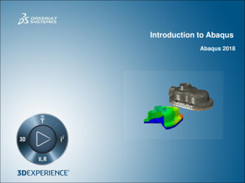
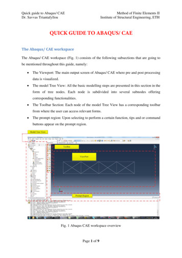
Quick guide to Abaqus/ CAEDr. Savvas TriantafyllouMethod of Finite Elements IIInstitute of Structural Engineering, ETHStep 5: Section AssignmentOn the Parts node in the Model Tree, double click on Section Assignments. Select theelements from the model viewport, then the Section created earlier from the combo boxand click OK. Thus, each line entity is attributed with a section property.Step 6: Model InstanceUnder the Assembly node in the Model Tree double click on Instances. Select Dependentfor the instance type and then click OK.Step 7: Model MeshUnder the Part node, double click on Mesh (Fig. 7).Fig. 7 Mesh node in Model TreeClick on the Assign Element Type in the toolbar.(a)(b)Fig. 8(a) Assign Element Type menu button (b) Seed Edges menu buttonThis is the element library of Abaqus (Fig. 9). Select Standard for element type, Truss for thetruss element and Linear to define the two node Isoparametric Element. Click OK.Page 5 of 9
Quick guide to Abaqus/ CAEDr. Savvas TriantafyllouMethod of Finite Elements IIInstitute of Structural Engineering, ETHFig. 9 Element Library FormIn the toolbox area click on the Seed Edge: By Number icon (hold down icon to bring up theother options). Select the entire geometry and click Done in the prompt area. Define thenumber of elements along the edges as 1 and click Enter in the prompt region then Done inresponse to the next prompt. In the toolbox area click on the Mesh Part icon. Click Yes in theprompt area to mesh the instance.Step 8: Analysis Type definitionDouble click on the Steps node in the Model Tree. The Create Step (Fig. 10) form appearswhere you can define the analysis type. For a linear static analysis or a NR scheme chooseStatic, General from the list box. For an Arc-length Riks type method choose Static Riks. ClickContinue, name the step then click OK to close the form. Please be careful of the differentparameters one should consider for the type of analysis s/he wishes to perform. In case of alarge displacement analysis, remember to check the Nlgeom radio button (Fig. 11).Page 6 of 9
Quick guide to Abaqus/ CAEDr. Savvas TriantafyllouMethod of Finite Elements IIInstitute of Structural Engineering, ETHFig. 10 Create Step formFig. 11 Nlgeom ParameterPage 7 of 9
Quick guide to Abaqus/ CAEDr. Savvas TriantafyllouMethod of Finite Elements IIInstitute of Structural Engineering, ETHStep 9: Boundary ConditionsDouble click on the BCs node in the Model Tree. The Create Boundary Condition formappears (Fig. 11). Name the boundary conditioned and select Displacement/Rotation forthe type. Click Continue then select the nodes at which Bcs should be assigned. Please notethe messages appearing on the prompt area (Fig. 12). Press Done in the prompt area. In theform choose the degrees of freedom you wish to restrain and set their corresponding valueto zero. Then click OK.Fig. 12 Create Boundary condition formFig. 13 Boundary condition definition prompt messagePage 8 of 9
Quick guide to Abaqus/ CAEDr. Savvas TriantafyllouMethod of Finite Elements IIInstitute of Structural Engineering, ETHStep 10: LoadsDouble click on the Loads node in the Model Tree. Name the load, and select Concentratedforce as the type. Click Continue and then select the points where loads should beassigned and press Done in the prompt area. In the next form define the values of theassigned loads and then click OK.Warning: Every time you decide to delete a STEP the corresponding loads and boundaryconditions will be also deleted.Step 11: Run AnalysisIn the Model Tree double click on the Job node, name the job, then click Continue and thenOK. In the toolbar click on Job Manager (Fig. 13). Press Submit to start the analysis. WhileAbaqus is solving the problem right click on the job submitted, and select Monitor to get infoon the analysis procedure. After the analysis is finished press on Results to open theVisualization module of Abaqus.Fig. 14 Job manager button in Job toolbarPage 9 of 9
from where the user can access relevant forms. The prompt region: Upon selecting to perform a certain function, tips and or command buttons appear on the prompt region. Fig. 1 Abaqus CAE workspace overview . Quick guide to Abaqus/ CAE Method of Finite Elements II Dr. Savvas Triantafyllou Institute of Structural Engineering, ETH Page 2 of 9 .