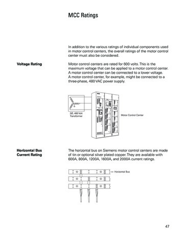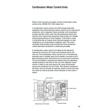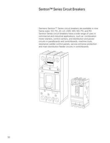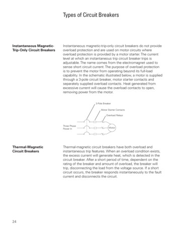
Transcription
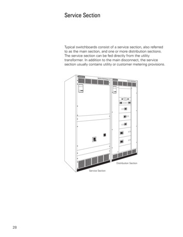
Service SectionTypical switchboards consist of a service section, also referredto as the main section, and one or more distribution sections.The service section can be fed directly from the utilitytransformer. In addition to the main disconnect, the servicesection usually contains utility or customer metering provisions.28
Service Entrance MethodsSeveral options are available to bring power into theswitchboard service section. Cable can be brought into theswitchboard from the top or the bottom.Cable can be brought into the top of the switchboard throughconduit. If the cable is a large diameter and more room isneeded a pull box, available in 10” to 30” heights, can be added.A bus duct entrance can be used when metal bus is usedinstead of cables.29
Cable may enter through a conduit to a disconnect that is fedfrom the bottom. A pull section can be added to the side of theservice section to pass cable to the top of the switchboard.Depending on the cable bending space, cable can be connecteddirectly to the lugs or to a cross bus. A cross bus brings the busconnections to the pull section eliminating the need to bendcables.30
Hot SequenceMetering can either be hot sequence or cold sequence. Thisrefers to whether or not power is still applied to the utilitymeter when the main disconnect is switched off. The followingdrawing illustrates hot sequence. When the main disconnect isopen, power is removed from the load. Power is still applied tothe utility meter.Cold SequenceThe following drawing illustrates cold sequence. When the maindisconnect is open, power is removed from the load and theutility meter.Hot sequence metering on the line side of the main disconnectis normal, but cold sequence metering on the load side of themain disconnect can also be provided.31
Service Section Main Disconnect DevicesThe service section of Siemens switchboards willaccommodate a variety of main protective devices. Selectiondepends on the characteristics of the electrical system and theneeds of the customer.Fusible Switches32One type of protective device is the Siemens Vacu-Break fusible switch. Fusible switches are available in ampere ratingsup to 1200 amps at 600 VAC.
HCP Fusible SwitchThe HCP type fusible switch is another device that can be usedin the service section as a disconnect device. Visible contactsprovide a visual indication concerning the state of the switchbefore servicing. HCP fusible switches are available withampere ratings from 400 to 1200 amps. HCP fusible switchesare suitable for use on systems with up to 200,000 amps ofavailable fault current with used with Class J or Class L fuses.MCCBsThe Sentron Series molded case circuit breakers (MCCB)can also be used as main service section protective devices.Sentron Series circuit breakers are available with ampere ratingsfrom 400 to 2000 amps, and interrupting ratings from 10,000to 200,000 amps. The Sentron Series circuit breaker is alsoavailable with solid state protection, referred to as Sensitrip III.Sensitrip III breakers are available with ampere ratings from 400to 3200 amps, and interrupting ratings up to 200,000 amps.33
Handle ExtensionIt can be difficult to operate some of the handles on the largercircuit breakers. A handle extension is available which allowsmore leverage to be applied to the circuit breaker handle. Thismakes opening and closing the circuit breaker easier.ICCBsInsulated case circuit breakers (ICCB) can be applied inapplications from 100 to 5000 amps through 600 VAC.There are four ICCB frames: 1200, 2000, 3200, and 5000amps. Interchangeable rating plugs and a continuous currentadjustment are provided with each trip unit. The frame ampererating is determined by the current sensors in the breaker.Interrupting ratings are available in ratings up to 200,000 amps.ICCBs can be fixed mounted or drawout mounted.34
Bolted Pressure SwitchBolted pressure switches can also be used as a maindisconnect. Bolted pressure switches are available in 800, 1200,1600, 2000, 2500, 3000, and 4000 amp frames. The maximumshort circuit current withstandability is 200,000 amps. Boltedpressure switches are rated for 240 VAC, 480 VAC, and 600VAC.RL Power Circuit BreakersRL power circuit breakers can also be used in switchboards.These circuit breakers are available in 800 to 5000 amp framesat 600 VAC. RL power circuit breakers are drawout mount.35
Distribution SectionThe distribution section receives power from the servicesection and distributes it to various downstream loads.Rear Alignment36Depending on the design of a specific switchboard, the servicesection cabinet may be deeper than the distribution section.This is due to the size of the main disconnect device andassociated bus requirements. The rear of all sections align sothe switchboard may be installed against a wall. This is referredto as rear alignment.
Front and Rear AlignedSwitchboards can also be front and rear aligned, if the depthof the service section and distribution section are the same. Insome switchboards the circuit protection devices and bus mayrequire a deeper cabinet. In other switchboards extra depth maybe added as an option.Protective DevicesLike the service section, the distribution section willaccommodate a variety of protective devices. Selectiondepends on the characteristics of the electrical system.In addition, motor control starters can also be used inswitchboards.DeviceCurrent RatingVacu-Break Fusible SwitchesBolted Pressure SwitchesHCP SwitchesMolded Case Circuit BreakersInsulated Case Circuit BreakersLV Power Circuit Breakers30-1200 amps800-4000 amps400-1200 amps15-3200 amps100-5000 amps800-4000 amps37
Review 31.Typical switchboards consist of a sectionand usually one or more section.2.A , available in 10” to 30”heights, can be added to the top of a switchboard toallow room for large diameter cable.3.A is added toaccommodate cable entering the bottom of aswitchboard and connected to the bus at the top of aswitchboard.4.means that power is stillapplied to the utility meter when the main disconnect isopen.5.means that poweris removed from the utility meter when the maindisconnect is open.6.Which of the following is suitable for use as a maindisconnect in the service section?a.b.c.d.e.f.7.fusible switchmolded case circuit breakerinsulated case circuit breakerbolted pressure switchRL power circuit breakerall the aboveThe section receives power from theservice section and distributes it to various downstreamloads.8. refers to a switchboardwhere the service section may be deeper than thedistribution section, and the rear of all sections arealigned.38
Power Supply SystemsSwitchboards receive power from a variety of sources.Downstream switchboards may receive power from upstreamswitchboards or disconnect switches, however, power for thedistribution system originates from a utility power company.Voltage from the power company is stepped down throughtransformers for distribution systems. The following are someexamples of systems in use. The amount of voltage on thesecondary depends on how much voltage is on the primaryand the ratio between the primary and secondary. The followingexamples are representative of some voltages commonly foundin distribution systems.1Ø3WThe following diagram illustrates one of the most commonsingle-phase, three-wire (1Ø3W) distribution systems in usetoday. There are 240 volts across the full secondary of thetransformer and 120 volts between the neutral and either endof the transformer. The neutral is the third wire.39
3Ø4W, Wye-ConnectedThe following illustration shows the secondary of a 480 Y/277V three-phase, four-wire (3Ø4W), wye-connected transformer.The “480 Y” indicates the transformer is wye-connected andhas 480 volts between any two phases. The “277 V” indicatesthere are 277 volts between any phase and neutral (N). Phaseto-phase voltage is 1.732 times phase-to-neutral voltage (277 x1.732 480). Neutral is the fourth wire.3Ø3W, Delta-ConnectedAnother method used in connecting transformers is a deltasecondary. In this example 480 volts is available phase-tophase.40
3Ø4W, Delta-ConnectedA three-phase, four-wire, delta-connected secondary worksa little differently. The following illustration shows a deltaconnected secondary with 240 volts phase-to-phase. Themidpoint of one phase winding is grounded to provide 120 voltsbetween phase A and neutral and 120 volts between phase Cand neutral. Between phase B and neutral, however, the voltageis 208 volts. This is referred to as the high leg.The high leg can be calculated by multiplying the phase A toneutral voltage times 1.732 (120 x 1.732 208). Single-polebreakers should not be connected to the high leg. NEC Article 215-8 requires that the high leg bus bar or conductor bepermanently marked with a finish that is orange in color. Thiswill help prevent electricians from connecting 120 volt singlephase loads to the 208 volt high leg. Four-wire, delta-connectedtransformers should always be wired so that theB phase to neutral is the high leg.41
Service Entrance EquipmentSwitchboards are often used as service entrance equipmentfor a building. The service section of a switchboard refers to thesection of a switchboard which receives incoming power. Thispower can be fed directly from utility power. Power can also befed to the section from another source, such as switchboard ordisconnect switch somewhere upstream.Service entrance equipment refers to the equipment throughwhich the power supply enters the building. The switchboard inthe following drawing is considered service entrance equipmentbecause it is where power enters the building. The incomingpower supply is connected to this equipment which provides ameans to control and cut off the supply. The National ElectricalCode discusses service entrance equipment in Article 230.Switchboards used as service entrance equipment must beapproved and labeled as such. All Siemens Sentron Seriesswitchboards are factory labeled as suitable for service entranceequipment when specified for service entrance.NEC and National Electrical Code are registered trademarks of theNational Fire Protection Association.42
Six Disconnect RuleService entrance conductors must have a readily accessiblemeans of being disconnected from the power supply. NEC Article 230.71 specifies that for each set of service entranceconductors no more than six switches or circuit breakers shallbe used to disconnect and isolate the service from all otherequipment. In the following example, a single main circuitbreaker will disconnect power to all equipment being suppliedby the service. There can be as many feeder and branchdisconnect devices as needed.In another example, a switchboard may be equipped with up tosix circuit breakers to disconnect power to all equipment beingsupplied by the service. In any case, the circuit breaker must beclearly labeled for the load it supplies.NEC and National Electrical Code are registered trademarks of theNational Fire Protection Association.43
It is important to note that the “six disconnect rule” refers tothe number of disconnects and not the number of poles. Forexample, in the illustration shown below there are 18 poles butonly six circuit breakers. Three poles are mechanically linkedtogether to form one disconnect device. In the illustratedconfiguration the service can be disconnected with no morethan six operations of the hand. This arrangement meets the“six disconnect rule”.44
Switchboard GroundingGrounding is an important aspect of any electrical systemand must be considered carefully. Article 250 of the NationalElectrical Code defines ground as a conducting connection,whether intentional or accidental, between an electrical circuitor equipment and the earth, or to some conducting body thatserves in place of the earth.The following illustration, for example, shows the neutral (N)conductor of a wye-connected transformer connected toground.There are two objectives to the intentional grounding ofelectrical equipment: Keep potential voltage differentials between different partsof a system at a minimum which reduces shock hazard. Keep impedance of the ground path to a minimum. Thelower the impedance the greater the current is in the eventof a fault. The greater the current the faster an overcurrentdevice will open.NEC and National Electrical Code are registered trademarks of theNational Fire Protection Association. Reprinted with permission from NFPA70-2002, the National Electrical Code , Copyright 2001, National FireProtection Association, Quincy, MA 02269.45
Neutral Disconnect LinkIf a switchboard service section is intended to be used asservice entrance equipment, provision must be included toisolate the neutral bus from the grounded neutral bus. A neutraldisconnect link is provided for this purpose. The followingdrawing shows the disconnect link in place.This removable link allows the branch neutral to be checkedfor continuity on the load side of the main disconnect. Thefollowing drawing shows the disconnect link removed.46
Service Entrance Grounding In the following drawing a switchboard is used as serviceentrance equipment. Power to the service section is receivedfrom a 3Ø4W service. The neutral is always grounded in serviceentrance equipment. The neutral is connected to groundthrough a neutral to ground connection and ground bus bar. Theground bus bar is connected to the frame of the switchboard,which is connected to the system or earth ground. The neutraldisconnect link is left in place to supply downstream loads.Three-phase, four-wire power is then supplied to downstreamloads.47
Downstream Equipment48The neutral is only connected to ground at the service entrance.When downstream equipment is used the neutral is isolatedin that equipment. As shown in the following illustration, theneutral is connected to earth ground through the groundbus bar of the service entrance switchboard. In this examplea second switchboard is used downstream of the serviceentrance switchboard. The enclosure of the downstreamswitchboard is connected to ground through a groundingconductor back to the service equipment. The neutral is notconnected to ground in the downstream switchboard. Noticealso that the second (downstream) switchboard does nothave a neutral disconnect link. Neutral disconnect links arenot required in switchboards used as non-service entranceequipment. Similarly the second switchboard will feedadditional downstream loads.
Review 41.If the secondary of a four-wire, wye-connectedtransformer is 480 volts phase-to-phase, the phase toneutral voltage is volts.2.If the secondary of a four-wire, B phase high leg, deltaconnected transformer is 240 volts phase-to-phase, thephase-to-neutral voltage isvolts A to neutralvolts B to neutralvolts C to neutral3.The term service section refers to the section of aswitchboard which receives incoming power. Theterm equipment refers toequipment through which the power supply enters thebuilding.4.According to NEC Article 230.71, the maximumnumber of circuit breakers that can be used todisconnect and isolate the service from all otherequipment is .5.A neutral is supplied inswitchboards used as service entrance equipment toallow the branch neutral to be checked for continuity onthe load side of the main disconnect.NEC and National Electrical Code are registered trademarks of theNational Fire Protection Association. Reprinted with permission from NFPA70-2002, the National Electrical Code , Copyright 2001, National FireProtection Association, Quincy, MA 02269.49
MCCBs The Sentron Series molded case circuit breakers (MCCB) can also be used as main service section protective devices. Sentron Series circuit breakers are available with ampere ratings from 400 to 2000 amps, and interrupting ratings from 10,000 to 200,000 amps. The Sentron Series circuit breaker is also