Transcription
GEOTECHNICAL INVESTIGATIONFORPROPOSED INDUSTRIAL SITE READINESS – KALLA LOTBESSEMER, MICHIGANJULY 15, 2020CEC PROJECT NO. GD‐200149
GEOTECHNICAL INVESTIGATIONFORPROPOSED INDUSTRIAL SITE READINESS – KALLA LOTBESSEMER, MICHIGANJULY 15, 2020CEC PROJECT NO. GD‐200149Prepared By:COLEMAN ENGINEERING COMPANY200 E. Ayer StreetIronwood, MI 49938
July 15, 2020Ms. Charly Loper, City ManagerCity of Bessemer411 S. Sophie StreetBessemer, MI 49911Re:Geotechnical InvestigationProposed Industrial Site Readiness – Kalla LotBessemer, MichiganDear Ms. Loper:Coleman Engineering Company (CEC) has completed the geotechnical investigation for theabove referenced project. Enclosed are two (2) copies of a Geotechnical Report that includes asummary of the field and laboratory activities associated with the investigation.We appreciate the opportunity to serve you. If you have any questions about our report, pleasefeel free to call me in our Ironwood office at (906) 932‐5048.Sincerely,COLEMAN ENGINEERING COMPANYGarth C. Stengard, P.E.Geotechnical Engineering ManagerGCS/ksEnclosureCEC Project No. GD‐200149
TABLE OF CONTENTSPAGE #I.INTRODUCTION .1II.FIELD PROCEDURES .1III.LABORATORY PROCEDURES .1. IV.SITE CONDITIONS.2V.ANALYSIS AND RECOMMENDATIONS .2Site Preparation and Grading .Shallow Foundations .Floor Slabs .Pavement Areas .Lateral Loads .Underground Utility Construction .Exterior Concrete Flatwork .Inspection and Testing .Construction Considerations .244456778LIMITATIONS OF SUBSURFACE EXPLORATION .9VI.APPENDIXAPPENDIX A. LOCATION MAPS‐ Project Location Map‐ Boring Location MapsAPPENDIX B. CLASSIFICATION OF SOILS FOR ENGINEERING PURPOSES(UNIFIED SOIL CLASSIFICATION SYSTEM)APPENDIX C. SOIL EXPLORATION‐GENERAL NOTES AND LEGENDAPPENDIX D. BORING LOGSColeman Engineering Company4Geotechnical Investigation ReportProposed Industrial Site Readiness‐Kalla LotJuly 15, 2020
I. INTRODUCTIONThe City of Bessemer is investigating their industrial areas for new building sites. This investigationcovers recommendations for the Kalla Lot. The site is located in the northwest quadrant of EliAvenue and Kalla Road in Bessemer, Michigan. Industrial buildings are typically one to two story,slab‐on‐grade structures. Wall and column loads were not known at the time of the report. Thepurpose of this report is to document the results of the field investigation and to providerecommendations/guidance for soil bearing capacity, settlement mitigation, groundwatermanagement, pavement design, earthwork quality assurance/control (QA/QC) and othergeotechnical considerations.II. FIELD PROCEDURESThe site was evaluated with a total of three (3) soil borings designated as B‐10 through B‐12. Theborings were advanced with a Diedrich D‐120 all‐terrain mounted drill unit present at the site onJune 19, 2020. Drilling was completed using 4 ¼‐inch I.D. hollow‐stem augers (HSA).The HSA act as continuously‐advancing steel casing that prevents the borehole walls fromcollapsing in above the depths to be tested/sampled. Sampling tools are lowered inside the augersfor testing into undisturbed soils ahead of the tip of the augers.Drilling and field sampling of soils were performed in accordance with American Society for Testingand Materials (ASTM) D‐1586, "Penetration Test and Split Barrel Sampling of Soils" with a 2‐inchO.D. split spoon. Twenty‐one (21) such samples were obtained.A field log was prepared for each boring during exploration, which contained the work method,standard penetration test (SPT) data, samples recovered and the indication of the presence ofvarious soil types. The field logs were submitted to Coleman Engineering Company’s (CEC)laboratory along with the soil samples for evaluation of the subsurface information and preparationof the final boring logs.The boring locations were selected by the City of Bessemer and established in the field by the CECdrill crew. Ground surface elevations at the boring locations were provided by the CEC SurveyCrew. The general project location and boring location maps are presented in Appendix A.III. LABORATORY PROCEDURESAll field soil samples collected were visually classified in accordance with ASTM D‐2488,Coleman Engineering Company1Geotechnical Investigation ReportProposed Industrial Site Readiness‐Kalla LotJuly 15, 2020
“Description and Identification of Soils (Visual‐Manual Procedure).” Because of the relativeuniformity and density of the subsurface conditions encountered and extensive past experiencewith local subsurface conditions, additional laboratory testing was deemed unnecessary.The final logs contain both factual and interpretive information. It should be emphasized that therecommendations are based only on the final boring logs. On the final logs, horizontal linesdesignating the interface between differing materials encountered represent approximateboundaries. The transition between soil strata is typically gradual.IV. SITE CONDITIONSThe site is sloping downward to northeast with corresponding elevations at the boring locationsranging from 1448.51 to 1452.65.The borings encountered interbedded layers of glacial sandy silt (ML), silty sand (SM) and poorlygraded sand (SP) to the maximum depths explored. The native soils were generally in a very looseto medium dense condition. For a more detailed soil description see the individual soil boring logsin Appendix D.Measureable groundwater was encountered in the borings at depths ranging from about 6.0 to 6.5feet below the existing ground surface corresponding to elevations 1442.51 and 1445.45. Thegroundwater levels may fluctuate several feet seasonally, owing to rainfall, snowmelt, surfacerunoff, and other factors.V. ANALYSIS AND RECOMMENDATIONSOur analysis and recommendations related to the geotechnical aspects of the proposed projectinclude:Site Preparation and GradingWe recommend that topsoil and any deleterious materials be stripped/excavated from within thebuilding footprint, building appurtenances, sidewalks, pavements and utilities to a lateral distanceequal to the depth of removal (1 foot horizontal to 1 foot vertical) and replaced with engineered fillas defined below.Excavations deeper than about 6.0 feet at this site will encounter groundwater. It is anticipatedthat groundwater will flow unpredictably into excavations at this depth. Any excavation that isColeman Engineering Company2Geotechnical Investigation ReportProposed Industrial Site Readiness‐Kalla LotJuly 15, 2020
anticipated to intersect the water table will require dewatering.Dewatering will likely need to be accomplished with a combination of a perimeter dewateringsystem or deep well system. Dewatering operations will need to be sufficient to allow fillplacement and foundation construction activities to take place in dry conditions. Dewateringshould lower the groundwater surface to at least 2 feet below the bottom of all excavations toavoid upward flow gradients that could destabilize the base of the excavation and so that anyrequired engineered fill placement can take place in “dry” conditions.Dewatering systems are typically installed in the field by contractors using “trial and error”methods. The contractor may need to adjust the system a number of times until finding acombination of pump size and well spacing best matched to the local conditions. In any case,prospective contractors will need to evaluate dewatering methods and discharge permittingappropriate to this project for themselves. Dewatering operations will need to be maintained 24hours a day, 7 days a week, until all construction activities taking place below the groundwatersurface are complete. Dewatering activities may require discharge permitting.All subgrades exposed after stripping/excavation should be evaluated by a geotechnical engineer orperson under the direction of a geotechnical engineer. The evaluation should include shallow handauger borings and/or dynamic cone penetrometer tests to determine if the native subgrade soilsare similar to those encountered in the soil borings and suitable for support of fill and structureloads. All native subgrade exposed after stripping/excavation should be compacted to a minimumof ninety percent (90%) of modified Proctor (ASTM D‐1557) maximum dry density prior to anybackfilling or placing foundations.Excavation equipment operating on an exposed subgrade that is within 12 inches of thegroundwater table may cause significant disturbance to bearing conditions of the soil. Therefore,we recommend that all excavation/stripping be accomplished using a tracked backhoe. Allconstruction traffic needs to be eliminated from traveling across the exposed subgrade untilfoundations have been constructed and the interior foundation walls have been backfilled.Engineered fill should consist of sand and/or gravel with less than about ten percent (10%) byweight of fines passing the No. 200 sieve with a maximum rock size of about 4 inches. A soilmeeting Michigan Department of Transportation (MDOT) specifications for Class II or IIA sandwould be acceptable for use as engineered fill. Fill shall be placed in lifts not exceeding about 12inches in loose thickness compacted to a minimum of ninety‐five percent (95%) of modified Proctor(ASTM D‐1557) maximum dry density. The on‐site poorly graded sand (SP) may be acceptable foruse as engineered fill pending the results of laboratory testing.Coleman Engineering Company3Geotechnical Investigation ReportProposed Industrial Site Readiness‐Kalla LotJuly 15, 2020
Shallow FoundationsWe recommend that any proposed buildings at this site be supported on conventional spreadfootings supported on native sand and/or compacted engineered fill. Foundations so supported canbe proportioned for a net allowable soil bearing pressure of up to 2,000 pounds per square foot.The net allowable soil bearing pressure refers to that pressure in excess of the final overburdenpressure. The recommended net allowable bearing pressure can be increased by one‐third forshort‐term transient type live loadings. For the recommended design soil bearing pressure, weestimate a total settlement of less than ¾ inch. Differential settlement is expected to approachfifty to seventy‐five percent (50 to 75%) of the total settlement for similarly sized structures andloads.All perimeter footings should extend to a minimum depth of 42 inches or below frost depth, asdefined by local building codes/practice. Interior footings in heated areas can be locatedimmediately below the floor slab. All continuous wall footings should have a minimum width of 16inches. An adequate thickness of insulation is recommended on the inside face of allfooting/foundation walls exposed to cold weather. All isolated exterior footings should extend aminimum depth of 60 inches or below frost depth, as defined by local building codes/practice.Floor SlabsAs with the footings, earth supported interior floors are recommended to be constructed on nativesoil or engineered fill. We recommend that the base of the slab be separated from the subgradewith an appropriate vapor barrier (Visqueen or similar). If the structure cannot accommodatecurling or shrinkage of the floor, industry standards often recommend burying the vapor barrierbeneath a minimum of 4 inches of free draining sand. However, we would caution that thispractice risks trapping water between the slab and vapor barrier. We recommend contacting thefloor covering manufacturer for placement of vapor barrier. If required, earth supported floor slabscan be designed using a modulus of subgrade reaction of 225 pounds per square inch per inch (pci)of deflection.Pavement AreasWe recommend that any deleterious materials be stripped/excavated from beneath the proposedpavement area as defined in the “Site Preparation” section. Excavation should extend to a depth toaccommodate the pavement section defined below. Where fill is required, we recommend it becompacted to at least ninety‐five percent (95%) modified Proctor density (ASTM D‐1557). Anynatural soils within 2 feet of top of subgrade should be scarified to a depth of at least 6 inchesColeman Engineering Company4Geotechnical Investigation ReportProposed Industrial Site Readiness‐Kalla LotJuly 15, 2020
before placing fill or pavements and then surface compacted. This is intended to disrupt any nearsurface seams of saturated sands, which could later result in weak spots or frost boils in thesubgrade.If there are areas which cannot be compacted, we recommend that the unstable materials besubexcavated to a depth of at least 2 feet and be replaced by materials which can be compacted.Ideally, the fill should be similar to the existing soils. Subsequent fill should be similarly moistenedand compacted.Prior to placing fill, we advise “proof‐rolling” the subgrade with a rubber‐tire roller or heavy truck.The rolling should be observed by a geotechnical engineer or a field technician under the directionof a geotechnical engineer. Soft or spongy areas should be sub‐cut, replaced and compacted asdirected. The surface of the subgrade should be graded so as not to create low areas where waterwill collect.Flexible Bituminous PavementFor the assumptions of a firm subgrade and light traffic volumes, we recommend a pavementsection of 3 inches of MDOT bituminous concrete surface course and 8 inches of MDOT 22Aaggregate base course for car and light truck areas. For heavy truck areas, we recommendincreasing the bituminous concrete thickness to 4 inches. The aggregate base course should becompacted to ninety‐five percent (95%) modified Proctor density; the bituminous concrete shouldbe compacted to ninety‐two percent (92%) Theoretical Maximum Density. Density tests should beconducted to confirm that these densities are achieved.Rigid Concrete PavementFor concrete pavements, we recommend a minimum pavement section of six inches of reinforcedPortland cement concrete and eight inches of MDOT Class IIA sand for uniform load support. Thesand base should be compacted to ninety‐five percent (95%) modified Proctor density. Densitytests should be conducted to confirm that these densities are achieved.Paved areas should be inspected frequently, particularly in the fall, and cracks sealed as soon aspossible.Lateral LoadsWe recommend using the following equivalent fluid pressures and a triangular‐shaped pressuredistribution for the design of any walls resisting lateral loads from soil backfill:Coleman Engineering Company5Geotechnical Investigation ReportProposed Industrial Site Readiness‐Kalla LotJuly 15, 2020
WALL TYPEEQUIVALENT ACTIVE FLUIDPRESSUREEQUIVALENT PASSIVE FLUIDPRESSURERestrained at top60 pcf300 pcfFree to rotate at top40 pcf300 pcfBackfill within 5 lateral feet of the back of the walls should consist of MDOT Class II Sand. Thebackfill should be compacted to at least ninety‐five percent (95%) of modified Proctor maximumdry density. Relatively light manually‐propelled compactors should be used within five (5) feet ofwalls. Compactors used beyond five (5) feet should be limited in weight to 3,000 lbs.A minimum 4‐inch diameter perforated flexible drainage pipe (ADS green stripe or similar) shouldbe located behind, parallel to, the wall, above the water table. The pipe should be embedded inwashed concrete aggregate wrapped with filter fabric (Mirafi 140N or similar). The pipe should berouted to gravity discharge away from any structure.External loads on the back of walls have not been taken into account in our recommendations.Surcharge loads imposed by vehicle parking, construction equipment and material storage shouldbe considered during structural design.Underground Utility ConstructionSoil types encountered during utility installation will likely be native sand. Based on the borings,the native sands encountered at depth are generally suitable for utility support provided theexcavations are adequately dewatered. If over‐excavation is required, we recommend that theunsuitable soils be removed a lateral distance equal to the depth of removal (1 foot horizontal to1 foot vertical) below the utility line and replaced with engineered fill. In the event that unstablesoils are encountered, it may be necessary to undercut these soils 1 to 3 feet (depth to bedetermined by field observation) and replace them with engineered fill as outlined in the sitepreparation and grading section in order to provide a stable work surface. Engineered fill belowutility lines should be compacted to a minimum of ninety percent (90%) modified Proctor density(ASTM D‐1557).All trench backfill above utility lines should be compacted to a minimum of ninety percent (90%) ofmodified Proctor maximum dry density. Trench backfill should be placed in lifts not exceedingabout 12 inches in loose thickness. Excavated soils are recommended for trench backfill above thepipe bedding material if they are at or can be brought, with reasonable effort, to the moisturecontent optimum for compaction as defined by the modified Proctor test (ASTM D‐1557). Also, theColeman Engineering Company6Geotechnical Investigation ReportProposed Industrial Site Readiness‐Kalla LotJuly 15, 2020
excavated soils shall be free of chunks of frozen soil, organics, cobbles and boulders larger thanabout 4 inches and other deleterious materials. If this is not the case, we recommend that allexcavations be backfilled with a soil recommended by a geotechnical engineer familiar with sitesubsurface conditions. Backfill to at least 12 inches above the pipe crown (pipe bedding) shouldconsist of MDOT Class II sand.Trench spoil, heavy equipment and any type of vibrating machinery should not be permitted withina lateral distance from the top of the trench/excavation equal to 0.5 times the depth of thetrench/excavation.Caving of trench sidewalls and soils at the site should be expected to occur at any depth andwithout warning. All utility trenches should be cut back or braced as required to provide safetrench working conditions. Trench safety is the responsibility of the utility contractor.Exterior Concrete FlatworkWe recommend that exterior concrete flatwork be supported on a minimum of 12 inches ofengineered backfill as defined in the “Site Preparation and Grading” section compacted to aminimum of ninety‐five percent (95%) of modified Proctor maximum dry density.We recommend that concrete entrance stoops be supported on frost‐depth footings to preventfrost heave from negatively impacting door operation. Walkways leading to the entrance flatwork,as well as other exterior concrete flatwork, should be supported on a minimum of 12 inches ofengineered fill placed over a firm subgrade. Exterior flatwork should be pitched to drain away fromthe building.Inspection and TestingA qualified testing laboratory should be retained throughout the course of earthwork operationsfor testing and documentation of compliance with the recommendations of this report and relatedproject specifications. As a guide, the following compaction testing schedule is recommended:Area or MaterialTo Be TestedRecommended MinimumTesting FrequencyNative Subgrades1 test per 2,500 sq. ft.Engineered Fill1 test per 2,500 sq. ft. per liftWall Footings1 test per 25 lineal feetUtility Trenches1 test per 50 lineal feet per liftColeman Engineering Company7Geotechnical Investigation ReportProposed Industrial Site Readiness‐Kalla LotJuly 15, 2020
Construction ConsiderationsWe anticipate that the sidewalls of excavations to depths greater than 4 feet below surroundinggrades will cave to 1 vertical to 1.5 horizontal or flatter. Excavation spoil, heavy equipment and anytype of vibrating machinery should not be permitted within a lateral distance from the top of theexcavation to 0.5 times the depth of the excavation. Excavation safety is the excavationcontractor's responsibility.Dewatering systems are typically installed in the field by contractors using “trial and error”methods. The contractor may need to adjust the system a number of times until finding acombination of pump size and well spacing best matched to the local conditions. In any case,prospective contractors will need to evaluate dewatering methods appropriate to this project forthemselves.Excavation equipment operating on an exposed subgrade that is within 12 inches of thegroundwater may cause significant disturbance to bearing conditions of the soil. Therefore, werecommend that all excavation be accomplished using a tracked backhoe. All construction trafficneeds to be eliminated from traveling across the exposed subgrade until foundations have beenconstructed and the interior foundation walls have been backfilled. Footing excavations should beperformed with a smooth bucket excavator to minimize disturbance to excavation bottoms.During construction, adequate provision should be made for proper drainage, so as to preventerosion and possible damage to this site and adjacent property. Temporary cut slopes duringconstruction above the water table should not exceed about 2:1 (horizontal:vertical). Post‐construction finished slopes above the water table should not exceed about 3:1(horizontal:vertical).Coleman Engineering Company8Geotechnical Investigation ReportProposed Industrial Site Readiness‐Kalla LotJuly 15, 2020
VI. LIMITATIONS OF SUBSURFACE EXPLORATIONServices performed by Coleman Engineering Company as part of this investigation have beenconducted in a manner consistent with that level of care and skill ordinarily exercised by membersof the engineering profession currently practicing under similar conditions. No other warranty,expressed or implied, is made.Subsurface conditions between borings will probably vary from those encountered at the locationswhere borings have been made. The data, interpretations and recommendations contained hereinare based solely on the information obtained from the three (3) soil borings completed for thisstudy.The conclusions and recommendations contained in this report are based on the assumption thatthe materials encountered in the borings represent the site conditions. If any unforeseendifficulties or unusual conditions are encountered, Coleman Engineering Company should becontacted immediately in order to make supplemental recommendations.This report completes our present assignment for this project. As the design nears completion, werecommend that you consult with us on unanticipated problems or questions regarding the designand/or review of any plans or specifications. The work assignments for the above services aresubject to your prior approval and authorization.OUR CONCLUSIONS AND RECOMMENDATIONS ARE PREDICATED ON OBSERVATION AND TESTINGOF THE EXCAVATION AND FOUNDATION PREPARATIONS BY QUALIFIED PERSONNEL. IT WOULD BELOGICAL FOR COLEMAN ENGINEERING COMPANY TO PROVIDE THAT SERVICE, SINCE WE ARE BESTABLE TO DETERMINE IF THE CONDITIONS ENCOUNTERED MATCH THOSE USED IN OUR ANALYSES,TO DETERMINE IF MODIFICATIONS OF OUR RECOMMENDATIONS ARE NEEDED AND TO MAKE SUCHMODIFICATIONS OF OUR RECOMMENDATIONS AS MAY BE NECESSARY. MODIFICATIONS OF OURRECOMMENDATIONS BY OTHERS RELIEVES US OF RESPONSIBILITY FOR THEM.This report has been completed by Garth C. Stengard, a registered engineer in the State ofMichigan.Garth C. Stengard, P.E.Geotechnical EngineerRegistration #: 6201050531Coleman Engineering Company9Geotechnical Investigation ReportProposed Industrial Site Readiness‐Kalla LotJuly 15, 2020
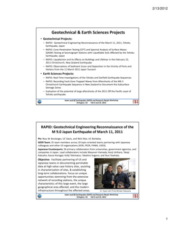
APPENDIX APROJECT LOCATION MAPS Project Location Map Boring Location Maps
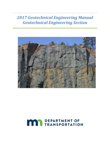
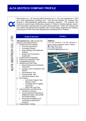
APPENDIX BCLASSIFICATION OF SOILS FOR ENGINEERING PURPOSES(UNIFIED SOIL CLASSIFICATION SYSTEM)
COLEMAN ENGINEERING COMPANY635 Circle DriveIron Mountain, Michigan 49801CLASSIFICATION OF SOILS FOR ENGINEERING PURPOSESASTM Designation: D-2487 – 83(Based on Unified Soil Classification System)Soil ClassificationGroupGroup NameBSymbolCriteria for Assigning Group Symbols and Group Names Using Laboratory TestsACoarse-Grained SoilsMore than 50 % retained onNo. 200 sieveGravelsMore than 50 % of coarsefraction retained on No. 4sieveSands50 % or more of coarsefraction passes No. 4 sieveFine-Grained Soils50 % or more passes theNo. 200 sieveSilts and ClaysLiquid limit less than 50Clean GravelsLess than 5 % finesCCu 4 and 1 Cc 3 EGWWell-graded gravel FCu 4 and/or 1 Cc 3EGPPoorly graded gravelFGravels with Fines morethan 12 % finesCFines classify as ML or MHGMSilty gravelF.G.H.Fines classify as CL or CHGCClayey gravelF.G.H.Clean SandsLess than 5 % finesDCu 6 and 1 Cc 3ESWWell-graded sandCu 6 and/or 1 Cc 3ESPPoorly graded sand lSands with FinesMore than 12 % finesDFines classify as ML or MHSMSilty sandG.H.J.Fines classify as CL or CHSCClayey sandG.H.I.inorganicPl 7 and plots on or above “A” lineJCLLean clayK.L.M.Pl 4 or plots below “A” lineMLSiltK.L.M.Liquid limit – oven driedLiquid limit – not driedOLJorganicSilts and ClaysLiquid limit 50 or moreinorganicorganicHighly organic soilsAEFOrganic siltK.L.M.O.CHFat clayK.L.M.Pl plots below “A” lineMHElastic siltK.L.M.Liquid limit – oven driedLiquid limit – not dried2Cu D60/D10Organic clayK.L.M.N.Pl plots on or above “A” linePrimarily organic matter, dark in color, and organic odorBased on the material passing the 3-in. (75-mm)sieve.BIf field sample contained cobbles or boulders, orboth, add “with cobbles or boulders, or both” to groupname.CGravels with 5 to 12 % fines require dual symbols:GW-GM well-graded gravel with siltGW-GC well-graded gravel with clayGP-GM poorly graded gravel with siltGP-GC poorly graded gravel with clayDSands with 5 to 12 % fines require dual symbols:SW-SM well-graded sand with siltSW-SC well-graded sand with claySP-SM poorly graded sand with siltSP-SC poorly graded sand with clay 0.75(D30)D10 x D60If soils contains 15 % sand, add “withsand” to group name.GIf fines classify as CL-ML, use dualsymbol GC-GM, or SC-SM.HIf fines are organic, add “with organicfines” to group name.IIf soil contains 15 % gravel, add “withgravel” to group name.JIf Atterberg limits plot in hatched area, soilis a CL-ML, silty clay.KIf soil contains 15 to 29 % plus No. 200,add “with sand” or “with gravel”, whichever ispredominant. 0.75OHOrganic siltK.L.M.Q.PTLOrganic clayK.L.M.P.PeatIf soil contains 30 % plus No. 200,predominantly sand, add “sandy” to group name.MIf soil contains 30 % plus No. 200,predominately gravel, add “gravelly” to groupname.NPl 4 and plots on or above “A” line.OPl 4 or plots below “A” line.PPl plots on or above “A” line.QPl plots below “A” line.
APPENDIX CSOIL EXPLORATION‐GENERAL NOTES AND LEGEND
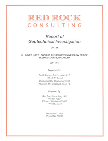
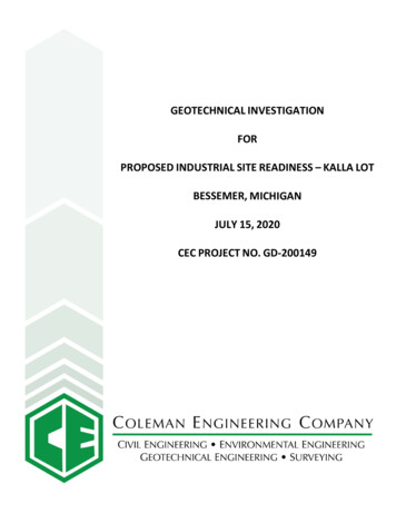
APPENDIX DBORING LOGS
COLEMAN ENGINEERING COMPANY635 CIRCLE DRIVEIRON MOUNTAIN, MICHIGAN 49801Telephone: (906)-774-3440 Fax: (906)-774-7776JOB NO.: 200149.GPJIndustrial Site ReadinessBORING NO.:B-10City of BessemerCLIENT:BORING LOCATION:RIG TYPE:1 OF 2Kalla Lot - 46.468798656 N, -90.075366730 (See soil boring location drawing)Diedrich D-120 ATVELEV.: 1452.65 /-DRILL CREW: C. Reidner / W. LakeDRILLING METHOD: 4-1/4" Hollow Stem AugerSPT AMPLEDATE COMPLETED: 6/19/200REVIEWED BY: D. EdlebeckSOIL DESCRIPTION(SM) SILTY SAND, brown, fine, with gravel, from0.0' to 2.0', moist, looseDATE: 7/10/20TEST RESULTSELEV. (FT)Soil CuttingsWATER TABLE6/19/20HOLE CLOSURE:DEPTH (FT)DATE STARTED:BORING DEPTH: 21.51452.71 4-4COMMENTS-200MOISTURECONTENT (%)PROJECT:LLPLT(tsf)qa(tsf)qu(tsf)4-1/4" Hollow Stem Auger2" SPT Sampling140# wt., 30" dropAuto Hammer224-5-5(10)1.234.trace clay from 4.5' to 7.0', medium dense35-8-5(13)1.051447.76Driller's note: Samples wet 6.0' to21.5'742-1-2(3)1.0.wet, very loose8952-2-3(5)1.210(Glacial Outwash) 9.5'(SP) POORLY GRADED SAND, brown, fine tomedium, some silt, wet, 19-AS-Auger Sample-BS-Bag Sample-RC-Rock-Core20-MC-Macrocore-PS-Piston Tube-2SS-2" Split Spoon-3SS-3" Split Spoon-2ST-2" Shelby Tube-3ST-3" Shelby Tube1432.7while drilling 6.0after drilling 6.0afterhoursBORING NO.:B-10
COLEMAN ENGINEERING COMPANY635 CIRCLE DRIVEIRON MOUNTAIN, MICHIGAN 49801Telephone: (906)-774-3440 Fax: (906)-774-7776JOB NO.: 200149.GPJIndustrial Site ReadinessBORING NO.:B-10City of BessemerCLIENT:BORING LOCATION:RIG TYPE:2 OF 2Kalla Lot - 46.468798656 N, -90.075366730 (See soil boring location drawing)Diedrich D-120 ATVELEV.: 1452.65 /-DRILL CREW: C. Reidner / W. LakeDRILLING METHOD: 4-1/4" Hollow Stem AugerSPT SAMPLEDATE COMPLETED: 6/19/2020REVIEWED BY: D. EdlebeckSOIL DESCRIPTION(SP) POORLY GRADED SAND, brown, fine, withgravel, some silt, wet, medium denseDATE: 7/10/20TEST RESULTSELEV. (FT)Soil CuttingsWATER TABLE6/19/20HOLE CLOSURE:DEPTH (FT)DATE STARTED:BORING DEPTH: 21.5COMMENTS 4-4-200MOISTURECONTENT l Outwash)2221.5
for testing into undisturbed soils ahead of the tip of the augers. Drilling and field sampling of soils were performed in accordance with American Society for Testing and Materials (ASTM) D‐1586, "Penetration Test and Split Barrel Sampling of Soils" with a 2‐inch O.D. split spoon.