Transcription
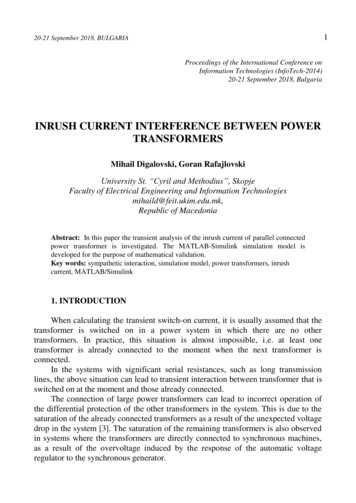
SELECTION OF CURRENT TRANSFORMERS & WIRE SIZING IN SUBSTATIONSSethuraman GanesanABB Inc.Allentown, PAABSTRACTMore and more sub-stations are retrofitted with numerical relays, meters and monitoring devices. Most often, the olderrelay gets replaced with a newer relay with the rest of the installation such as Current Transformer (CT) and leadremaining undisturbed. Utilities have standardized on their older current transformers and want to maintain the samecurrent transformer specifications throughout their system even in their newer installation. An extension of the aboveapproach is that even the cable leads and panel wiring sizes are over-specified resulting in totally unjustified cost ofinstallations as well as difficulty in terminating such wires in the modern panels and equipment.On the other end of the spectrum, in rare cases, the existing CT sizes and lead sizes of electromechanical relays may not beadequate for the latest protective relays which might demand a different current transformer performance. A carefulevaluation of current transformer size and their leads is recommended, either to save an appreciable cost of installation orto avoid costly protection mis-operation or non-operation.This paper systematically lists and analyses such requirements for various modern protective relays. This work is expectedto be a good reference source for the new generation utility protection engineers in selecting the CTs and wire sizes andunderstanding impact of various connections in determining the reliability of components in the installation.1. INTRODUCTIONThe foremost interface device between the power system and the protective relaying is the ubiquitous current transformer.The standard current transformer secondary winding is rated at 5A as per ANSI standards. Other rated currents such as 1Aexist elsewhere. The main purpose of a current transformer is to translate the primary current in a high voltage powersystem to a signal level that can be handled by delicate electromechanical or electronic devices. The secondary connecteddevices could be indicating or energy integrating instruments, protective relays, transducers etc. Since the applications areso varied, it is natural that the CT be properly specified, depending on the exact application to which it is applied. To thisextent, it is necessary to understand some of the fundamental ways the CTs behave. This paper makes an attempt topresent the basics to understand the behavior and application of the CTs. The bibliography at the end of the paper providesmore detailed analysis and application data.2. CHARACTERISTICS OF CTThe current transformer primary is connected in series with the device in which the current is to be measured. SinceCurrent Transformer is fundamentally a transformer, it translates the current from the Primary to the Secondary side,inversely proportional to the turns so as to maintain the relationship,IP n ISwhere, n is the turns ratio of turns between the secondary and primary winding. Mostly, the primary of a CT is a straightthrough bar, meaning the number of turns on the primary is just 1. Hence n is often the number of turns of the secondary.
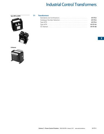
Figure 1a. Simplified equivalent circuit of a current transformerFigure 1b. Phasor diagram of a Current TransformerThe relationship above is assuming an ideal current transformer without any losses and negligible magnetizing current. Inactual practice, the CTs draw a current to keep the iron core excited and drop a voltage proportional to the currenttransformed because of the inherent resistance of its windings. An equivalent circuit of a CT is represented by Figure 1a,where Xm represents the magnetizing current reactance and RCT represents the internal winding resistance.The current transformer is expected to deliver about 5A or lower under healthy load conditions. The current goes to a highvalue if a fault occurs. As per ANSI, the CT ratio shall be chosen so that the maximum symmetrical fault current on theCT secondary is limited to 100A. Since it is very difficult to meet the high accuracy requirement for billing purposes nearrated current as well as maintain an acceptable linearity for protection at current levels of 100A, it is usual to separate thefunctions to two different sets of CT cores.2.1 Specifying Metering core Current TransformerThe main concern here is that the CT core is sized to adequately meet the burden requirements. The burden includes theconnected metering burden as well as the lead burden. The metering class CT is specified with accuracy rating for eachstandard burden for which it is rated. An example provided in IEEE C57.13 is 0.3 B-0.1 and B-0.2, 0.6 B-0.5. Thenumber after the letter B indicates the standard burden in Ohms at a power factor of 0.9. The number 0.3 or 0.6 indicateaccuracy class.Protection class CT is mostly accurate enough to drive a set of indication instruments (but may not be good enough forrevenue class summation energy metering). One disadvantage of using protection class CT for indication is that the CT iscapable of being driving up to 100A and beyond, which the delicate metering equipment may not be able to withstandthermally. In such cases the norm is to provide an interposing auxiliary transformer, star/star connected. The auxiliarytransformer is arranged to saturate for currents beyond a few 10s of amperes. While specifying metering or auxiliarycurrent transformers, the design burden needs to be closely matched to the actual connected burden. Connecting too low aburden compared to the design burden of the current transformer will allow higher currents through the meteringequipment before saturation comes into play.2
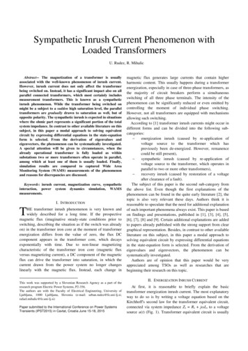
Often a scheme is required to sum up the currents from two more incomers, to arrive at the net current or power flow intothe switchgear. A special auxiliary transformer with multiple primary 5A windings is common. The secondary windingrating is chosen based on the net current expected with two or more of the incomers in service (Figure 2).AIncomer-1Incomer-2600A Max600A Max600/5A600/5A5 5 / 5A Aux CTSwitchgearFigure 2. Summation Auxiliary Current Transformer2.2 Specifying Protection Class Current TransformersIn order to specify or check the ratings of a current transformer, a thorough understanding of the application is required.With respect to ANSI CTs, some of the major details that one would look for in the CT are:CT Ratio, frequency etc.PolarityClass, Saturation Voltage, Knee point voltageExcitation characteristicsVoltage rating, current rating, thermal ratings etc. to suit primary power system2.2.1 CT RatioThe ratio is expressed in terms of rated primary and secondary currents. Excluding special applications, the primary ratinghas to be more than the maximum current that the primary of the current transformer is expected to carry. When the CT islocated in the outgoing feeder circuit, the maximum primary current is the same as the maximum feeder current. The nextthing to check is the maximum symmetrical fault current. Choose the primary rating so that with the maximum faultcurrent, the CT secondary current is less than 100A. In short the primary rating shall be above the load current as wellabove 1/20th of the fault current in such applications. With respect to 100A maximum secondary fault current, exceptionsoccur often in case of HV transformer CT applications where the load currents are quite low compared to the maximumfault current. A thorough application check with respect to the CT performance and the withstand capability and linearityof the connected devices need to be thoroughly checked.In ‘ring main’ or ‘breaker-and-a-half’ schemes the primary current rating is decided by the current flowing across the busand accordingly the CT primary rating is chosen. As we will see further, choosing a higher CT ratio increases theavailable knee point voltage to the relay, but the secondary current gets reduced greatly. The latter could be an issue whereload matched currents is expected such as transformer differential protections.Rarely CTs are provided with primary taps and require special attention with respect to selecting the ratios. Since a coupleof cores are stacked inside a CT, changing the primary tap would result in changing the ratios of all the cores. Necessaryadjustments may have to be done on the CT secondary taps of the other cores to maintain their ratios.2.2.2 PolarityPolarity is not of direct concern for non-directional Phase OC relays. However, where ground relaying is concerned thepolarities are to be properly observed before residual connections are formed.3
As regards directional protection applications, their operation depends on the phase angle of the measured current withreference (polarizing) signal. It is mandatory to observe the polarity of the current transformer secondary in suchinstallations.2.2.3 Class, Knee point voltage, excitation characteristicsThe major error of a CT can be attributed to the magnetizing current drawn. Hence, the excitation characteristics definethe performance of the CT best. With both primary and secondary open, a voltage is applied across the secondary and thecurrent drawn is measured and plotted on a log-log graph.In this graph, the knee point voltage is defined as the point on the excitation curve where the tangent is at 45 degree to theabscissa. The log-log graph paper shall be with square decades. (The definition here is applicable for non-gapped CT core,which exist in most of the installations in the U.S. More details and definitions are available in IEEE standard for airgapped cores.)The knee point voltage represents the point beyond which the CT becomes non-linear. Further voltage increases will makethe CT draw larger currents. Beyond a certain level, the primary and secondary windings physically exist next to eachother, but the magnetic coupling becomes insignificant. The current in the CT secondary is no longer influenced by theprimary current.2.2.3.1 AC Saturation:The TOC curve of the earlier electromechanical relays was achieved by allowing partial saturation of the internal magneticcircuits. Currents much higher than the higher limits of the TOC relays, which cause ‘partial’ saturation of the CTs shouldnot affect the applications. However, if an application involves severe CT saturation, the relay may not function. Wherethe CT ratio is very low, CT secondary currents could exceed 20 times rated current causing severe saturation. The netoutputs of such CTs may become so low (Figure 3) that operation of most of the protections become impossible.Figure 3. CT secondary waveform when severe AC saturation occursTo avoid saturation, the CT shall develop adequate voltage such thatVX If (RCT RL RB)-------(1)where,If Fault current on CT secondary (Amps)RCT CT Secondary resistance (Ohms)RL CT Secondary total lead resistance (Ohms)and RB CT secondary connected burden (Ohms)4
The lead resistance RL is the total secondary loop lead resistance. In case of single phase to ground faults, the current fromthe CT secondary flows through the phase connection and returns through the neutral wire. Hence twice the ‘one-way’ leadresistance shall be considered. In case of multi-phase faults, the phase currents cancel out with negligible current in thecommon neutral return lead. Hence the lead resistance for such faults will be just that of the ‘one-way’ lead. Special casesarise with delta connected CTs. In all such cases a very careful evaluation of how the CT under question drives currentsthrough the leads would be necessary.2.2.3.2 Transient Saturation:Transients, especially the decaying DC waveform in the primary current, cause the CT to go into saturation and producedistorted current waveform. Once the transients vanish the steady state performance of the CT gets restored.To further understand the phenomenon of saturation of CT during DC transients, one has to understand how and why theDC transients occur in the power system and its effects on the CT.Considering a fault in a Transmission line, the moment a fault occurs, one would expect the currents to follow therelationship I V/Z. This equation, however, represents a simplified steady state Phasor relationship. Assuming a pureinductive circuit, if the fault occurs at maximum point of wave, the current which was earlier zero, would rise from thatvalue, and hence no transients are to be expected.However, fault may occur when the voltage waveform goes through near zero. The steady state waveform indicates thatthe current should be at the maximum value when the fault occurs. This is impossible since the inductance in thetransmission system does not allow an instantaneous change from current zero level prior to fault to a high value just afterthe incidence of the fault.Solving the differential equation of the fundamentals of the inductive circuit, it can be proven that the inductance woulddraw a combination of steady state DC current as well as an alternating current waveform, with apparently noinstantaneous change in the current value prior to and after the incidence of the fault (Figure 4).In practical applications the DC current is not sustained but decays with a time constant equal to the system time constantL/R where L is the inductance in Henry and R is the resistance in Ohms of the primary power system.Figure 4. Components of currents in an inductive circuit with maximum DC transientsTransient behavior of CT:Reverting back to the subject of current transformers, it is definitely burdened with the task of translating not only thesteady state AC current waveform but also the DC transient. While current transformers are designed to work withtransferring alternating current, the situation here warrants translating DC current from the primary to the secondary side.CTs use magnetic field to couple the electrical signal from primary to the secondary side using dynamic ‘changes’ ratherthan absolute magnitude. The voltage induced in the secondary is thus proportional to the ‘rate of change’ of the magneticflux. Assuming CT secondary burden to be purely resistive, the voltage across the CT is directly proportional to thecurrent.Consideringi CT secondary current (instantaneous)v CT secondary voltage (instantaneous)Φ Flux in the magnetic core5
iwhere dα v α (d Φ/d t)Φ/d t represents the rate of change of flux with respect to timeRewriting the last part of the above,i α (d Φ/d t)Integrating both sides, i α Φ------ (2)In other words, the flux necessary to drive a current is proportional to the area under the envelope of the current waveshape.Figure 5a indicates the variation of flux when AC current waveform is involved. Figure 5b indicates the excursion of fluxwhen translation of DC offset transient waveform is involved. In the first case, the flux excursion involves increasing aswell as decreasing flux. Thus the saturation flux limits are not reached. However, in the latter case, integration of theunidirectional DC waveform involves excursion of the flux only in the increasing direction. The longer the DC transient,the larger will be the excursion of the flux level, resulting in exceeding the saturation limits of the iron core, causing totaldistortion of the output waveform.Figure 5a. Excursion of flux waveform Φ is well within the saturation limits withAC current waveforms6
Figure 5b. Excursion of flux waveform Φ shoots past the saturation limits quicklywith DC transientsFigure 6 indicates the actual CT secondary current waveform when CT saturates because of the requirement to translateprimary DC current transients.Figure 6. Saturation due to DC transient distorts the AC waveform output as wellIt is clear that to produce the DC offset along with an AC waveform without distortion, the requirement of the steelcore flux in the CT is not just twice the flux required for the AC waveform but much larger, big enough to sustainthe growth of flux as long as the DC transient persists.7
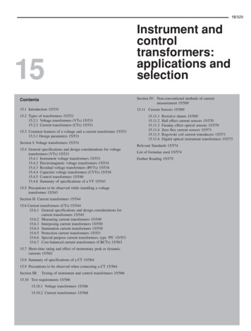
It can be shown that the CT shall have enough capacity to develop the following voltage not to saturate at all for acombination of AC and DC transient.VX If (1 X/R) (RCT RL RB)------(3)where,If Fault current on CT secondary (Amps)X System primary reactance (Ohms)R System primary resistance (Ohms)RCT CT Secondary resistance (Ohms)RL CT Secondary total lead resistance (Ohms)and RB CT secondary connected burden (Ohms)Note that there is an additional factor (1 X/R) on the right side of the equation compared to the equation applied for ACsaturation, Equation (1).The ANSI specifies CTs for protection performance by a letter (See IEEE Std C57.13- 1993). The classification codes areC, K and T. The classification C and K are widely used for protection. They indicate that the winding is uniformlywound around the core with negligible leakage flux. The C class CT is furnished with excitation characteristics which canbe used to “Calculate” the CT performance. The standard ratings are C100, C200, C400, C800 corresponding to 100, 200,400 and 800 volts respectively at 100A CT secondary. This would mean the design burdens are 1, 2, 4 and 8 Ohmsrespectively. Other burdens such as 0.1, 0.2 and 0.5 with corresponding voltages 10, 20, 50 are also specified but are notoften used for HV and EHV applications. ANSI specifies the power factor of the burden at 0.5.A steady state current error of 10% is allowed at 100A secondary, which translates into 10A excitation current. It is easyto look up the CT excitation characteristics corresponding to 10A excitation current and find out the induced voltage insidethe CT. Subtracting the internal drop of RCT through 100A fault current from the voltage should be above 100, 200, 400or 800V to classify the CT as either C100, C200, 400 or 800. In figure 7a, corresponding to maximum tap ratio of 600/5A,the voltage developed corresponding to 10A excitation current is 150V. The RCT for this ratio is 0.296 Ohms. So thevoltage developed across the external burden is 150-100x 0.296 which is about 120V. The CT is designated as C100which is the next lower rating below 120V. The knee point voltage for the above tap is about 70V. Note that when a lowertap is adopted the voltage available for the relay application comes down proportionately.The K classification is the same as C rating but the knee-point voltage must be at least 70% of the secondary terminalvoltage rating. The letter T indicates the ratio error must be determined by ‘Test’. There are other classification types Hand L, which are older specifications and are no longer in use.An ANSI C800 CTs will have a saturation voltage of about,Vx 100(RCT 8)Here 100 represents the recommended maximum CT secondary current of the CT during fault conditions ( 20 timesnominal current of 5A), 8 is the burden expected to be connected to C800 class CT.Comparing against the earlier equation (3), to avoid saturation,100(RCT 8) If (1 X/R) (RCT RL RB) -------(4)----(5)Define Ni 100/IfNr {RCT 8(design burden for C800)} / (RCT RL RB)Substituting in (4) above,(1 X/R) Ni Nr---8
In other words, in order not to have CT saturation, the factor (1 X/R) can be accounted for partly by reducing actualsecondary current during fault to less than 100A. Sometimes an attempt is made to increase the CT ratio to achieve theabove. The factor Nr can be manipulated often reducing the secondary connected burden so. The latter is achieved byreducing the connected relay burden (almost zero with the latest numerical relays), reducing the lead resistance (by eitherreducing the distance between the relay to the CT, multiple parallel runs of CT leads, thicker wire size etc.). Note thatincreasing the CT ratio increases Ni factor but also increases Nr factor because of increased CT secondary resistance. Theeffects may cancel out if the connected lead burden resistances are low compared to the CT secondary resistance. In a fewoccasions when higher CT ratios are not possible in the main CTs, auxiliary CTs close to the CT location to step down thecurrent flowing through the lead and hence effectively reducing the net lead resistance, as seen by the CTs, have beensuccessfully applied.Figure 7a. Typical ANSI CT secondary exciting characteristics(Chapter 5, Protective Relaying Theory and Applications, book edited by Walt Elmore, ABB Inc., published by Marcel Dekker Inc)9
Figure 7b. ANSI CT secondary terminal voltage with rated burdens of 1, 2, 4 and 8Ohms forC100, C200, C400 and C800 CTs(Chapter 5, Protective Relaying Theory and Application, book edited by Walt Elmore, ABB Inc., published by Marcel Dekker Inc)Example:What can be the maximum lead resistance for the application of a distance relay with the following data?Primary fault current 10kA (from system study)System X/R 15 (from system study)CT ratio 1000/5ACT rating C400 (CT existing)Design burden 4 Ohms (as per standards for C400 CT)CT resistance 0.25 Ohms (Data from manufacturer)Relay burden Negligible (numerical relay)Calculations:Secondary fault current 10000/ (1000/5) 50ANi 100/50 2Nr (RCT 4) / (RCT RL RB) (0.25 4) / (0.25 RL) 4.25/ (0.25 RL)10
Substituting in the inequality (5),(1 X/R) Ni Nr(1 15) 2 x 4.25 / (0.25 RL)Solving for RL,RL 0.28 OhmsIn other words the lead resistance shall be kept less than 0.28 Ohms.HV systems are designed with high X/R to reduce the losses to the minimum. X/R ratios can be as high as 30 for EHVsystems. Apparently where X/R ratios are high, they have to be accounted for by a combination of higher C rating, lowerfault current, and lower CT secondary loop resistance.Residual flux:An additional dimension to the above issue is the residual magnetizing field (remanence) left over in the CT core onclearance of a fault. When a fault with a heavy DC transient occurs, the flux density may go to a very high level. Once thefault is cleared, due to magnetic retention of the excited material, a certain amount of magnetism is retained. This has beenfound to be as high as 90% in some of the magnetic material.In other words, in order to design a CT which will always reproduce the currents accurately, it may be necessary toincrease the CT size by a term (1 X/R)/ (1-ψ) where ψ represents the per unit of maximum flux remaining in the CT coreafter removal of the primary fault current.For example if the residual flux is 25%, ψ 0.25. So the resultant CT sizing requirement goes up by a factor 1/ (1- ψ) 1/(1-0.25) 1.33. In other words the requirement goes up by 33%. In case the CT retains 90% residual flux, it can be seenthat the requirement of the CT size goes up by a factor of 900%.Caution: The continuity or polarity of a current transformer is tested before putting it into service. DC test current injectedinto the CT will cause a unidirectional flux build up, sufficient to cause adequate residual magnetic flux that may interferewith relay operation. It is very difficult to get rid of the residual flux once established. Special de-magnetizing procedureis adopted to reduce the remaining flux.During faults, if the remanence flux direction is opposite to that of the transient DC current, the CT will produce correctsecondary waveform. On the contrary, if the remanence flux and the DC transient occur in the same direction, a moredistorted waveform than usual occurs.Various methods are used to reduce the effects of remanence (Std. IEEE C37.110):a. Using different grades of steel for the coreb. Gapped corec. Biased core CTs.Of the three, the second method is widely practiced and is discussed further.Introduction of air gap will surely increase the magnetizing current, but will reduce remanence. It has been observed thatthe increase in the magnetizing current is often very small. The cost of such CTs are higher since they call for specialconstruction and tolerance limits of the gap over the lifetime of the CT.A lot of the installations in the U.S. have non-gapped iron core with high remanence. It might appear that the CTs arelikely to saturate whenever fault occurs. However, this is not true for the following reasons:1.Most of the faults are ground faults which tend to have lesser DC offset and associated saturation issues. Theground faults tend to have more resistance (lower X/R ratio). Ground faults rarely occur with maximum DCoffset due to the fact that the onset of a fault is less probable near zero crossing of the voltage waveform. (Notehowever that in case of faults involving multi-phases, one or the other phase will always have DC offset becauseof phase angle differences between the phases involved.)11
2.The inequality considered earlier assumes no saturation. Modern high-speed relays operate quite fast, oftentaking an internal trip decision quite earlier than the onset of saturation even after considering remanence.It is possible to calculate the time to saturate for any CT given the set of saturation voltage, remanence level, details ofconnected burden etc. Once the time to saturation is known a quick check against the time of operation of the protectiverelay would indicate whether the application would function properly with respect to the CT characteristics. Special careis needed when high speed autoreclose is concerned since the remanance magnetism and the CT secondary transienteffects are the maximum when a reclose is attempted with a permanent fault on the line. Figure 8 provides a graphicalrepresentation of time to saturation of a CT. Detailed mathermatical terms to calculate ‘time-to-saturate’ are available inIEEE C37.110.Figure 8. Time to saturate as a function of the saturation voltage and secondary circuitresistanceIEC standards have special classifications for CTs with gaps and specify their performance and remanence limits (IEC60044-6)3. CT REQUIREMENTS FOR VARIOUS PROTECTION APPLICATIONSOnce the CT specifications are known, it is necessary to match against the requirements of the protections. The followinghighlight some of the most often used protections and how CTs are matched for proper performance.3.1 Time OC protectionTOC protection demands currents up to about 20 to 30 times the set current. The transient saturation is not of concernsince the protection operating times are much after the CT comes out of saturation. AC saturation is of concern and CTsaturation voltage has to be checked against the voltage generated during maximum fault conditions at which grading withother protections are provided.3.2 High SetThe operating times of High-set Phase or Ground OC elements are of the order of about a cycle. To ensure high speed ofoperation, it is essential to check both AC saturation as well as transient saturation of the CT. Where CT saturation cannotbe avoided, it is necessary that the highest operates before the CT starts saturating on transients.12
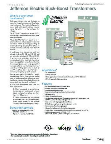
3.3 Distance ProtectionThe lines usually carry higher primary amperes. The ratios are high resulting typically in currents much lower than 100A.Saturation during transient is of major concern. Saturation is accepted after the operation of the Zone-1 operation. Delayedelements of Zone-2 and Zone-3 are given necessary logic circuits to ride through the saturation time of the currenttransformers before recovery occurs after the DC transients decay or some minor errors in their operating times aretolerated.3.4 Differential protectionBiased differential protection applications have operating characteristics with pickup increasing with higher through faultcurrents. This is defined by a slope of the bias characteristics. The higher the slope, the larger is the tolerance of the relayto errors and CT saturation. Some differential protections have multiple slope characteristics. Higher slopes are providedfor higher through fault currents to account for possible CT saturation. The disadvantage of higher slope is that the relaymight need higher currents for severe in-zone faults. This is overcome in modern numerical relays using special saturationdetectors or special through fault detectors. When there is no saturation or when no through fault is detected, a low slope isretained, resulting in very sensitive differential protection. With severe saturation or with through fault detection, the slopegets automatically increased resulting in good stability. Relay designs exist which decide whether the fault is internal orexternal within a few milliseconds, well before any CT saturation occurs and need very minimum CT voltage. Relaymanufacturers can provide reduced requirements of CT with such special logics.A special case of differential protection is High Impedance scheme, used for Bus bars, generator windings and Yconnected or auto transformer windings. CTs of identical ratios with very low leakage reactance and magnetizing currents,exclusively for this use is recommended. Lower magnetizing current is recommended to have as good a sensitivity ofprotection as possible. The CT knee point voltage rather than the saturation voltage is of concern here. In this schemeCTs on all the incoming and outgoing circuits are paralleled together, the junction point is formed in the switchyard. Theidea is to limit the lead resistance between the CTs to the minimum. A high impedance voltage operated relay is connectedacross the junction point. The lead resistance from the junction point to the relay is not critical, and in fact, as will seefurther actually helps in stability of the relay for external faults.Figure 9. Equivalent circuit of High Impedance Differential Scheme with one of the CTs fullysaturatedThe relay is set such that,setting VR K x If x (RL RCT ) (Volts)If Secondary Fault current (Amps)RL CT secondary lead resistance (Ohms)RCT CT secondary resistance (Ohms)K Margin Factor ( 1 for full saturation)Saturation factorSFVk Vk / If (RL RCT) CT Knee point voltage13
Refer to manufacturer guidelines for relationship of SF with respect to K.During external fault, the CT on the faulted feeder may saturate during DC transients. However since the equiva
transformer is arranged to saturate for currents beyond a few 10s of amperes. While specifying metering or auxiliary current transformers, the design burden needs to be closely matched to the actual connected burden. Connecting too low a burden compared to the design burden of the current transformer will allow higher currents through the metering