Transcription
Meeting the DO-160 LightningProtection 10800.926.8722
White PaperRead AboutRadio Technical Commission for Aeronautics (RTCA)DO-160 Qualification TestingTransient Pulse ProtectionIntroductionIt has been said that airplanes are the safest form of travel. Ifthat is true, it is because of the efforts of countless engineersand technicians who design aviation equipment to functionproperly in a wide variety of conditions. As an example, anaircraft is designed so that externally mounted equipmentsuch as antennae, exterior lights, air data probes, externalsensors, and anti-ice equipment can withstand the effects ofa direct lightning strike.The analysis of external equipment must also considerall connecting cables and associated terminal equipment.One fairly obvious issue is that the aircraft designer has toprevent the lightning strike from igniting the aircraft’s fuel, a200 microjoule sensitive fuel mixture. There is substantial artand science in the design of an aircraft which insures thatthe hundreds of thousands of Amperes of electricity from alightning bolt flow through the skin of the aircraft and backout to the atmosphere (and eventually to ground). Defenseembedded electronics within an aircraft are subject to a similarset of challenges posed by lightning strikes. This white paperwill address both the industry standard that sets guidelines forlightning protection and the design practices that are used tocomply with the standard.Meeting the Design and Compliance ChallengesRequirements flow down from the department of defense orthe prime contractor with specifications aimed at lightningsafety qualification. This can often lead to confusion. Forexample, how does a Single Board Computer (SBC) protectitself against a 210,000 Amps direct lightning hit? What isrequired to comply with the applicable standard and how isthe compliance validated?As an aerospace electronics and COTS embedded computingchassis and backplane vendor, Atrenne Computing Solutionsfrequently has customers bring us these questions. ManyC4ISR electronics system integrators lack experience withstandards like DO-160 Section 22 and 23, which providethe specific guidelines for testing the resilience of a unit ofequipment against lightning effects. Familiarity with theDO-160 standard and understanding design options forcompliance are part of the guidance we offer to our integratorcustomers, helping them overcome these issues.2
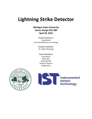
White PaperLightning: Direct vs Indirect EffectsDirect EffectsAn aircraft is divided into zones. Some of these zonesare protected from high voltage transients. Other zonesare required to survive a high voltage direct strike. One ofthe important challenges is that a platform designer mustunderstand how cabling and other conductive elementscan couple a high energy transient to equipment in variousparts of the aircraft.Most airframes are made of metal and compositematerials. If lightning were to strike the nose of the aircraft,for example, the charge would travel outside the plane tothe tail and continue to ground through the atmosphere.The construction of the airframe acts as a Faraday cagewith as low an impedance path as possible. This typeof design minimizes coupling voltages and currents onthe internal cabling and wiring of the aircraft and protectsmission critical components located internally.Conductive Metal Skin Keeps Electricity from theInterior of the PlaneEMF InterferenceUnshielded cable is not generally considered a “bestpractice,” but it is sometimes used due to its lighter weight.Even in cases where the huge surge of charge from alightning direct effect has been safely conducted throughthe aircraft, unshielded cable would be more susceptibleto EMF (electromagnetic field) interference which canstill wreak havoc on sensitive electronics. The transientcurrent from an EMF is termed a Lightning Indirect Effector Lightning Induced Transient. A shielded cable containsinsulation between the center conductor and the outershield. A properly shielded cable will see very little EMF,even with the residual charge of a direct lightning strikeon the outside of the shield, and will allow electronics tocontinue to operate normally without interference.Recently, aircraft construction has increasingly usedcomposite materials which are very lightweight but havegreater impedance than metal frames. As impedanceincreases, it is more likely that voltages and currentswill couple directly onto internal cables and into theavionics and other electronic equipment on the aircraft.Fortunately, design strategies within the electronics canmitigate these effects.The platform designer must take electrical coupling intoconsideration in the overall platform system design. Oneof the challenges is that equipment internal to the aircraftcan be electrically coupled to the externally mountedequipment by means of cabling. For example, an ISRback-end processing system is usually connected to anexternally mounted sensor with a direct cable. Opticalcabling is often preferred for these types of applicationsas it can be specified to run a desired length and it avoidsthe issue of electromagnetic coupling entirely.Wherethat is not practical, properly shielded cables can isolatecurrent to the external skin (chassis ground) of sensitiveelectronics thus mitigating the lightning direct effect.An EMF pulse on an unshielded cable can be on the orderof 100 Amps at a few hundred volts, which is significantlymore severe than a typical electrostatic discharge (ESD)from a human body. An experienced designer canmitigate these effects to a specified level by using designelements to clamp the voltage or sink current. This isclearly a last line of defense after considering everythingelse possible at the platform (aircraft) architecture level.3
White PaperQualification TestingAirborne Equipment”) which seeks to define a minimumstandard set of test procedures for airborne equipmentEMF noise coupled to an unshielded cable enters aprocessing subsystem through one of the external IOinterfaces, essentially via one of the interface pins. Thetest to determine whether a system can withstand an EMFtransient introduces a charge to the system’s IO interfacepins. This is called a pin injection test. Pin injection testsdetermine whether damage is caused if transient voltageand current are injected directly into the electronics viathe external IO pins. During a pin injection test, the pointof injection is usually directly onto the IO pin with returnto case ground.DO-160 (or its precursor, DO-138) has been used as astandard for environmental qualification testing since1958. These test procedures allow safety stakeholdersto validate performance characteristics of equipmentunder conditions which are similar to those encounteredin actual flight. In defense electronics, DO-160 servesas a set of design criteria and a standard for qualificationtesting. It appears frequently in RFP/RFQ’s that specifycomponents or solutions for airborne platforms.RTCAT h e Te s t i n g G u i d e l i n e s A d d r e s s e d i nRT C A / D O - 1 6 0 I n c l u d e :The RTCA (Radio Technical Commission for Aeronautics)is a non-profit organization, founded in 1935, dedicatedto providing guidance and recommendations related toaviation and aviation electronic systems. It serves as apublic-private partnership of more than 300 organizationsinternationally, including airlines, defense contractors,government agencies, manufacturing companies, R&Dlabs and electronic component suppliers. The organizationfunctions as a Federal Advisory Committee which meansthat it provides advice and recommendations (notmandates) to the Federal Aviation Administration (FAA)and is governed by certain rules such as the requirementfor open meetings, public involvement and reporting.RTCA recommendations are effectively the work productof members and stakeholders of the aviation communitywho work together in a consensus-based, collaborative,peer-reviewed environment.The organization’srecommendations are not official statements of lawor policy but they are often used as the basis forgovernment and private sector aviation decisions and canbe incorporated into law by a government agency withrelevant statutory jurisdiction.The DO-160 StandardOne of the key functions of the RTCA is to recommendsolutions that increase safety and efficiency of airtravel. One of the most important standards is DO-160(“Environmental Conditions and Test Procedures for4 Temperature and Altitude Induced Signal SusceptibilityTemperature VariationHumidityVibrationExplosive AtmosphereWaterproofnessFluids SusceptibilitySand and DustFungus ResistanceSalt FogPower InputVoltage SpikeAudio Frequency Conducted Susceptibility —Power InputsRadio Frequency SusceptibilityEmission of Radio Frequency EnergyLightning Induced Transient SusceptibilityLightning Direct EffectsIcingElectrostatic Discharge (ESD)Fire, FlammabilityEnvironmental Test Identification
White PaperLightning Induced Transient SusceptibilityRTCA/DO-160, Section 22As discussed above, the direct lightning strike on an aircraft causes indirect voltage transients due to magnetic or electricfield coupling. These indirect effects are covered specifically in Section 22 of RTCA/DO-160. Section 22 provides testmethodology and procedures to validate that a set of equipment is able to withstand lightning induced effects such as theEMF pulse that is an indirect effect of a lightning direct hit. Note that RTCA/DO-160, Section 23 is a separate section thatdeals with Lightning Direct Effects. Table 1 defines lightning direct and indirect effects.TABLE 1EffectDefinitionQualification Testing GuidelinesDO-160 SectionLightning Direct EffectsHuge surge of charge from a direct lightning hitto equipment mounted externally on an aircraftSection 23Lightning Indirect EffectsThe transient current and voltage spikeintroduced into electronics cables as a result ofthe magnetic field generated by a large surgeof charge traveling through the frame of theaircraft. Sometimes called a lightning transientor lightning induced effect.Section 22Table 1 Testing Guidelines for Lightning EffectsDO-160 Section 22 allows equipment to be tested to an appropriate anticipated exposure level consistent with the expecteduse and installation location on the aircraft. There are five levels for internal aircraft equipment and interconnecting wiring:TABLE 2LevelDescriptionFocus of Mitigation1Well-protected environmentIO Panel2Partially protected environmentIO Panel3Moderately protected environmentIO Panel4 and 5Severe electromagnetic environmentsPlatform design, shieldingTable 2 Environmental LevelsThe aircraft is divided into a variety of zones and each of these zones has an associated electromagnetic severity profile.Some zones are subject to severe EMF indirect effects due to electromagnetic coupling and must be designed and testedto Level 5. Conversely, equipment installed in a well-protected environment (Level 1) has the least stringent requirements.C4ISR equipment based on the VPX architecture that needs to operate in Levels 4 and 5 must have the proper shieldingand support from the platform architecture. Mitigation strategies within the design of the IO board and IO front panel aretypically effective only to Level 3 and below, due the electronic component size required to safely suppress the Level 4 and5 transients.5
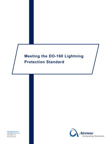
White PaperDO-160 Electronics Testing DetailsThere are two basic types of tests in RTCA/DO-160 Section 22:Pin injection tests – a simulated EMF pulse is applied directly to the pins of the external IO interface, usually between eachpin and the case ground. The purpose of this test is to demonstrate that the equipment under test displays the desiredtolerance to transient current without disturbing application execution.Cable bundle tests – a transient pulse is applied by cable induction or ground injection. The pulse may be applied to thecables one at a time or to the entire set of cables simultaneously.Below is a table from DO-160 Section 22 which describes voltage and current transient wave forms. DO-160 specifiesseveral canonical wave forms which emulate Lightning Induced Transients.Table 3Waveform (Voltage) / Waveform 600Table 3 Waveform Generator Setting Levels for Pin Injection*Voc – Peak open circuit Voltage (Volts)Isc – Peak short circuit current (Amps)The standard defines a series of prototypical waveforms which are used to apply current and voltage to the interface pinof the unit under test. Table 3 above shows the general setting levels for pin injection testing. It shows the range of peakvoltages and currents required to be qualified to various Levels. For example in the middle column of the table above, whenpin injection tests are performed at Level 3, the voltage (300V) spike follows Waveform 4 and the current (60A) spike followsWaveform 1. Waveform 1 and Waveform 4 are shown below, which in this case, happen to be in phase and identical.Both Waveforms (see below) show a fast rise to peak amplitude and then a slower degradation. Other wave forms includevariations of Waveform 1, sinusoids and multi-stroke pulses.Waveform 4Waveform 16
White PaperDesign ConsiderationsESD Protected ComponentsProtection ComponentsDesign for RTCA/DO-160, Section 22 qualification requiresa review of each interface individually and a designstrategy for each. The design of the chassis IO panel canincorporate lightning protection circuitry depending on theunique requirements of each interface component. Forexample, a component with ESD protection is designedto survive a spike characteristic of a human electrostaticdischarge, typically an 8 µsec pulse of 15 kV. When apulse of this magnitude is encountered, the part has someclamping current limit, for example, th
These indirect effects are covered specifically in Section 22 of RTCA/DO-160. Section 22 provides test methodology and procedures to validate that a set of equipment is able to withstand lightning induced effects such as the EMF pulse that is an indirect effect of a lightning direct hit. Note that RTCA/DO-160, Section 23 is a separate section that deals with Lightning Direct Effects. Table 1 .